warning RENAULT TWINGO 2009 2.G Panelwork Owner's Guide
[x] Cancel search | Manufacturer: RENAULT, Model Year: 2009, Model line: TWINGO, Model: RENAULT TWINGO 2009 2.GPages: 209
Page 104 of 209
41D-13
REAR LOWER STRUCTURE
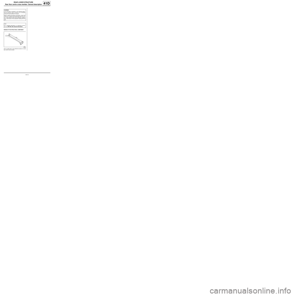
Rear floor centre cross member: General description
41D
DESIGN OF THE STRUCTURAL COMPONENT
This is a basic part; it only fulfils the function of a rear
floor centre cross member.WARNING
The information contained in the following descri-
bes the general repair procedure for all vehicles
having the same design for this part.
Before reading this general information, check that
there are no special notes associated with this vehi-
cle. These special notes will be specified if applica-
ble in other parts of this subsection dealing with the
par t.
Note:
For a detailed description of a particular connec-
tion, see MR 400, 40A, General Information.
120932
Page 106 of 209
41D-15
REAR LOWER STRUCTURE
Rear floor centre cross member: Description
C44
41D
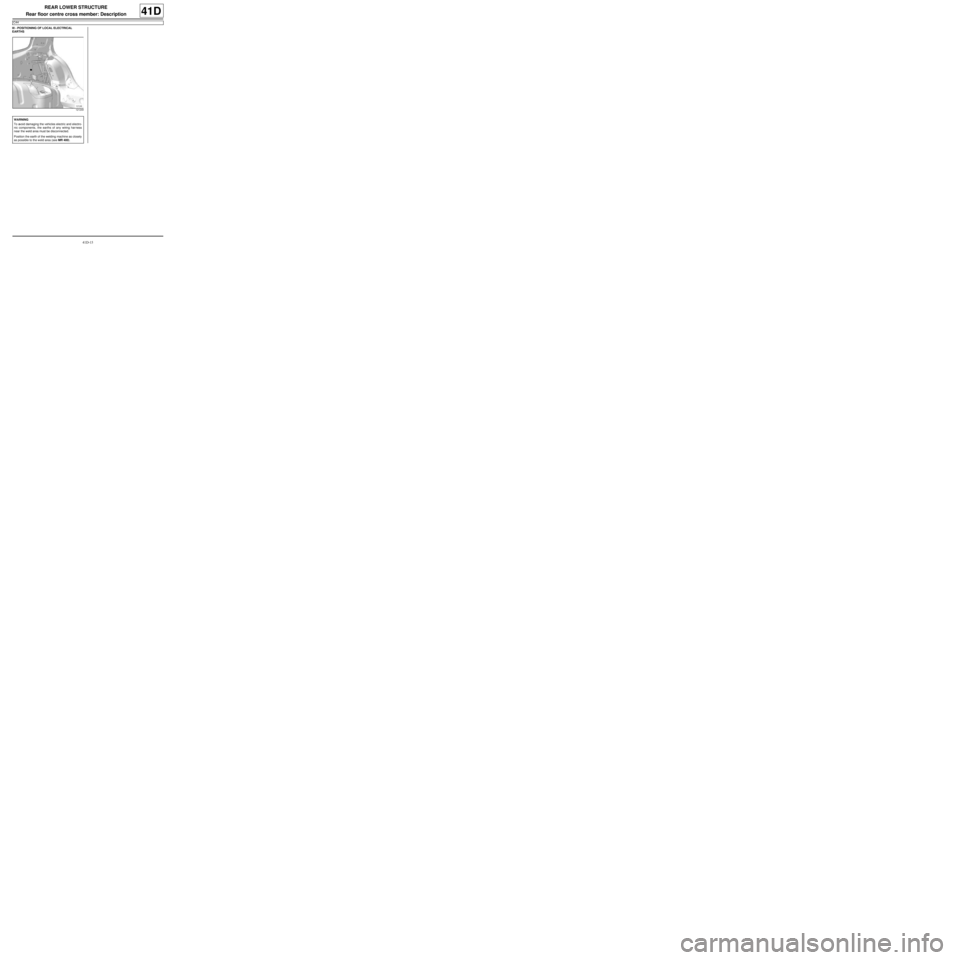
III - POSITIONING OF LOCAL ELECTRICAL
EARTHS
121249
WARNING
To avoid damaging the vehicles electric and electro-
nic components, the earths of any wiring harness
near the weld area must be disconnected.
Position the earth of the welding machine as closely
as possible to the weld area (see MR 400).
Page 107 of 209
41D-16
REAR LOWER STRUCTURE
Rear towing eye: Description
41D
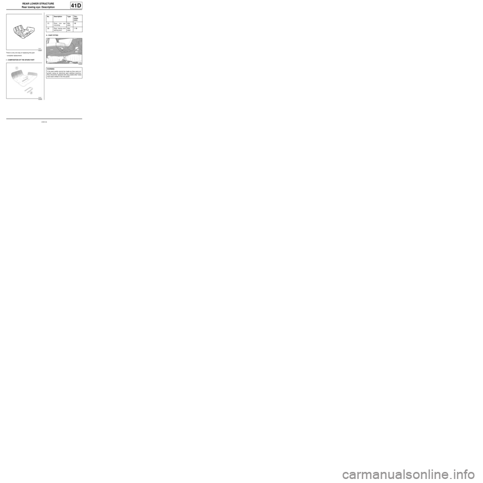
There is only one way of replacing this part:
-complete replacement.
I - COMPOSITION OF THE SPARE PARTII - PART FITTED
120931
120908
No. Description Type Thic-
kness
(mm)
(1) Rear tow eye
mountingMild
steel1.8
(2) Rear towing and
lashing wireMild
steel∅ 10
120909
WARNING
If the spot welds cannot be made as they were ori-
ginally using an electrical spot welding machine,
they should be replaced with plug welds after holes
have been drilled in the first panel.
Page 115 of 209
42A-6
FRONT UPPER STRUCTURE
Front wing upper mounting support: General description42A
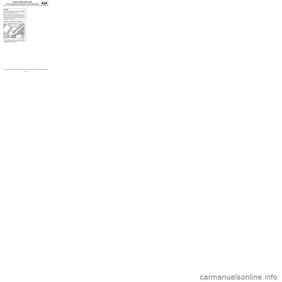
DESIGN OF THE STRUCTURAL COMPONENT
This is a basic part, it fulfils the function of front wing
upper mounting support and it enables the front wing to
be adjusted in the X and Y axes.WARNING
The information contained in the following descri-
bes the general repair procedure for all vehicles
having the same design for this part.
Before reading the following general information,
make sure that there are no special notes associa-
ted with the vehicle. These special notes are speci-
fied if necessary in other par ts of the sub-section
dealing with the component.
121237
Page 120 of 209
42A-11
FRONT UPPER STRUCTURE
Headlight carrier panel: Removal - Refitting
42A
REMOVAL
I - REMOVAL PREPARATION OPERATION
aRemove:
-the front bumper (see Front bumper: Removal -
Refitting) (MR 412, 55A, Exterior protection),
-the halogen headlight (see Halogen headlight:
Removal - Refitting) (MR 411, 80B, Headlights),
-the bonnet catch (see Bonnet lock: Removal -
Refitting) (MR 412, 52A, Non-side opening ele-
ment mechanisms),
-the front upper cross member (see 42A, Front up-
per structure, Front upper cross member: Re-
moval - Refitting, page 42A-13) .
II - OPERATION FOR REMOVAL OF PART
CONCERNED
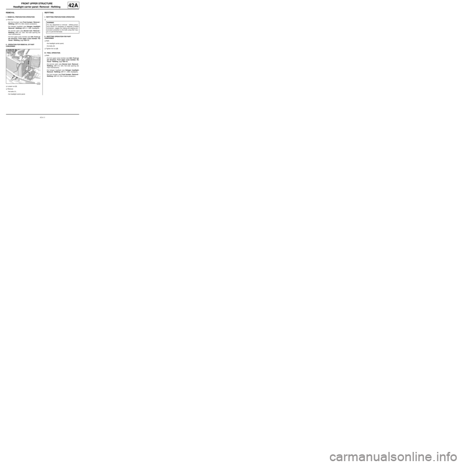
aLoosen nut (2) .
aRemove:
-the bolts (1) ,
-the headlight carrier panel.
REFITTING
I - REFITTING PREPARATIONS OPERATION
a
II - REFITTING OPERATION FOR PART
CONCERNED
aRefit:
-the headlight carrier panel,
-the bolts (1) .
aTighten the nut (2) .
III - FINAL OPERATION.
aRefit:
-the front upper cross member (see 42A, Front up-
per structure, Front upper cross member: Re-
moval - Refitting, page 42A-13) ,
-the bonnet catch (see Bonnet lock: Removal -
Refitting) (MR 412, 52A, Non-side opening ele-
ment mechanisms),
-the halogen headlight (see Halogen headlight:
Removal - Refitting) (MR 411, 80B, Headlights),
-the front bumper (see Front bumper: Removal -
Refitting) (MR 412, 55A, Exterior protection).
121251
WARNING
For any adjustment or removal - refitting proce-
dure where it is necessar y to separate a bolted
connection, reapply the mating and sealing anti-
corrosion protection to the bolts using filler mas-
tic in a pre-formed bead.
Page 121 of 209
42A-12
FRONT UPPER STRUCTURE
Front upper cross member: General description
42A
DESIGN OF THE STRUCTURAL COMPONENT
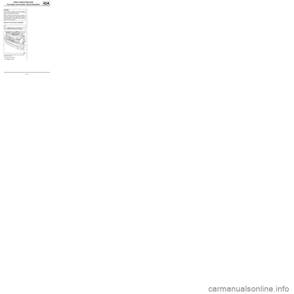
The special feature of this part it that it concurrently
serves two functions:
-front upper cross member,
-front headlight mounting. WARNING
The information contained in the following descri-
bes the general repair procedure for all vehicles
having the same design for this part.
Before reading the following general information,
make sure that there are no special notes associa-
ted with the vehicle. These special notes are speci-
fied if necessary in other par ts of the sub-section
dealing with the component.
Note:
For a detailed description of a particular connec-
tion, see MR 400, 40A, General Information.
121036
Page 123 of 209
42A-14
FRONT UPPER STRUCTURE
Scuttle side panel: General description
42A
I - DESIGN OF THE STRUCTURAL COMPONENT
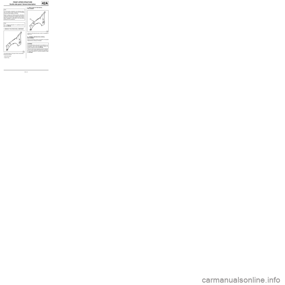
The special feature of this part it that it concurrently
serves two functions:
-scuttle side panel,
-A-pillar lining.II - AREA TO BE CUT FOR PARTIAL
REPLACEMENT
Cutting line (2) shows the area in which it is possible to
make a cut.
III - ASSEMBLY METHOD FOR A PARTIAL
REPLACEMENT
Only the connections which are specific to the partial
replacement by cutting are indicated.
If there are other issues regarding access to mating fa-
ces, the various replacement options are described in
the basic instructions for structural bodywork repair
(see MR 400). Note:
The information contained in the following descri-
bes the general repair procedure for all vehicles
having the same design for this part.
Before reading the following general information,
make sure that there are no special notes associa-
ted with the vehicle. These special notes are speci-
fied if necessary in other par ts of the sub-section
dealing with the component.
Note:
For a detailed description of a particular connec-
tion, see MR 400.
109831
110561
WARNING
If the mating faces of the parts to be welded are not
accessible, make EGW plug welds to replace the
original resistance welds (see MR 400).
Page 128 of 209
42A-19
FRONT UPPER STRUCTURE
Upper reinforcement of scuttle side panel: Description42A
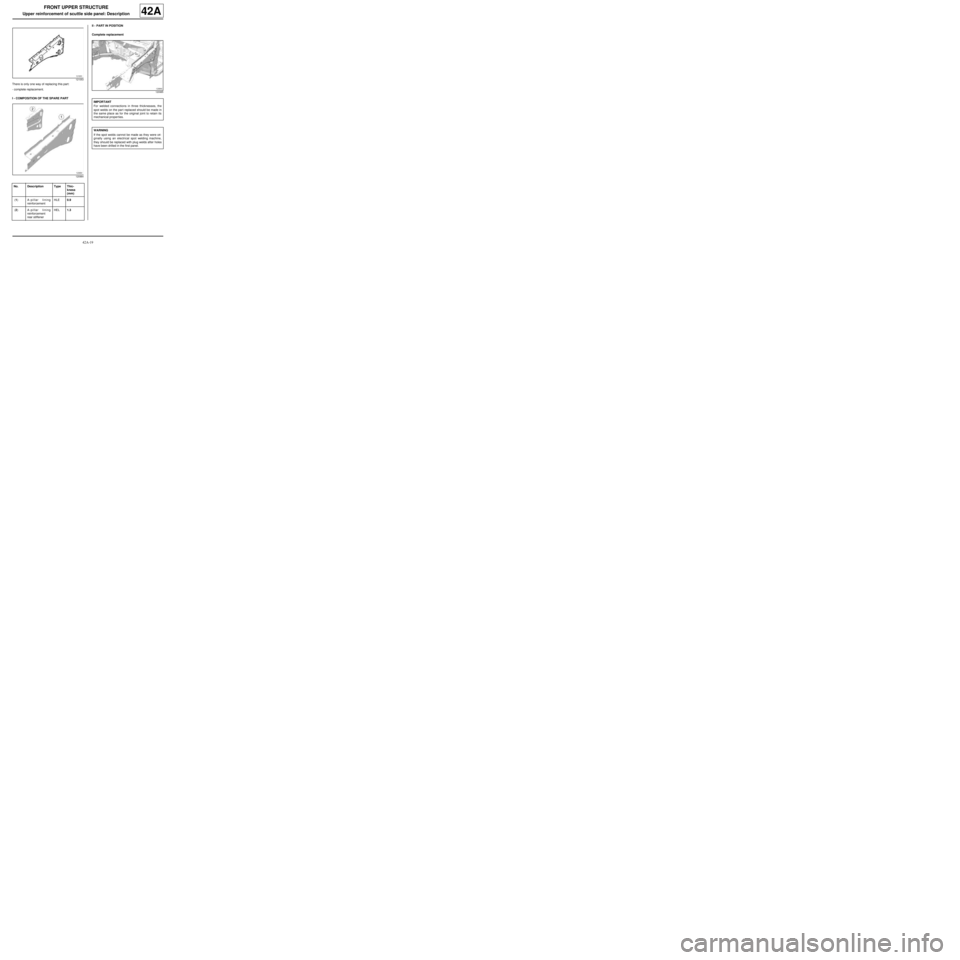
There is only one way of replacing this part:
-complete replacement.
I - COMPOSITION OF THE SPARE PARTII - PART IN POSITION
Complete replacement
121053
120984
No. Description Type Thic-
kness
(mm)
(1) A-pillar lining
reinforcementHLE0.9
(2) A-pillar lining
reinforcement
rear stiffenerHEL1.3
120985
IMPORTANT
For welded connections in three thicknesses, the
spot welds on the par t replaced should be made in
the same place as for the original joint to retain its
mechanical proper ties.
WARNING
If the spot welds cannot be made as they were ori-
ginally using an electrical spot welding machine,
they should be replaced with plug welds after holes
have been drilled in the first panel.
Page 133 of 209
42A-24
FRONT UPPER STRUCTURE
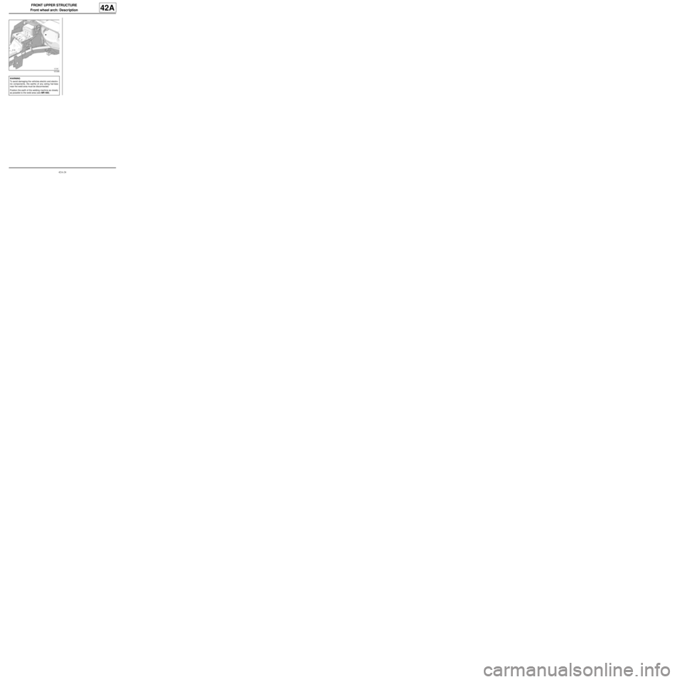
Front wheel arch: Description
42A
121246
WARNING
To avoid damaging the vehicles electric and electro-
nic components, the earths of any wiring harness
near the weld area must be disconnected.
Position the earth of the welding machine as closely
as possible to the weld area (see MR 400).
Page 134 of 209
42A-25
FRONT UPPER STRUCTURE
Front wheel arch, front section: General description
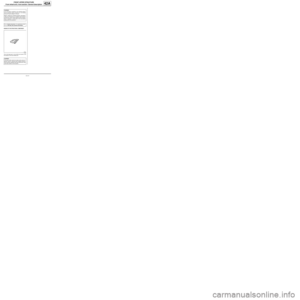
42A
DESIGN OF THE STRUCTURAL COMPONENT
This is the basic part; it only fulfils the function of the
front section of the front wheel arch.WARNING
The information contained in the following descri-
bes the general repair procedure for all vehicles
having the same design for this part.
Before reading the following general information,
make sure that there are no special notes associa-
ted with the vehicle. These special notes are speci-
fied if necessary in other par ts of the sub-section
dealing with the component.
For a detailed description of a particular connec-
tion, see MR 400, 40A, General Information.
110658
WARNING
If the spot welds cannot be made as they were ori-
ginally using an electrical spot welding machine,
they should be replaced with plug welds after holes
have been drilled in the first panel.