warning RENAULT TWINGO 2009 2.G Panelwork Repair Manual
[x] Cancel search | Manufacturer: RENAULT, Model Year: 2009, Model line: TWINGO, Model: RENAULT TWINGO 2009 2.GPages: 209
Page 151 of 209
43A-14
SIDE UPPER STRUCTURE
Body side: Description
C44
43A
121245
WARNING
To avoid damaging the vehicles electric and electro-
nic components, the earths of any wiring harness
near the weld area must be disconnected.
Position the earth of the welding machine as closely
as possible to the weld area (see MR 400).
Page 152 of 209
43A-15
SIDE UPPER STRUCTURE
Upper body: General description
43A
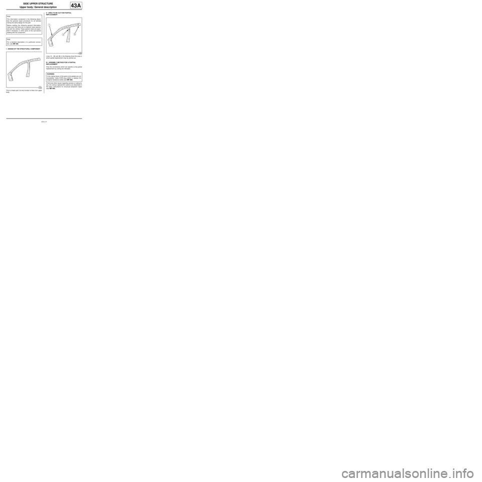
I - DESIGN OF THE STRUCTURAL COMPONENT
This is a basic part; its only function is that of an upper
body.II - AREA TO BE CUT FOR PARTIAL
REPLACEMENT
Lines (1) , (2) and (3) in the drawing show the area in
which partial replacement may be carried out.
III - ASSEMBLY METHOD FOR A PARTIAL
REPLACEMENT
Only the connections which are specific to the partial
replacement by cutting are indicated.
If there are other issues regarding access to mating fa-
ces, the various replacement options are described in
the basic instructions for structural bodywork repair
(see MR 400). Note:
The information contained in the following descri-
bes the general repair procedure for all vehicles
having the same design for this part.
Before reading the following general information,
make sure that there are no special notes associa-
ted with the vehicle. These special notes are speci-
fied if necessary in other par ts of the sub-section
dealing with the component.
Note:
For a detailed description of a particular connec-
tion, see MR 400.
110603
110604
WARNING
If the mating faces of the parts to be welded are not
accessible, make EGW plug welds to replace the
original resistance welds (see MR 400).
Page 155 of 209
43A-18
SIDE UPPER STRUCTURE
Upper body: Description
43A
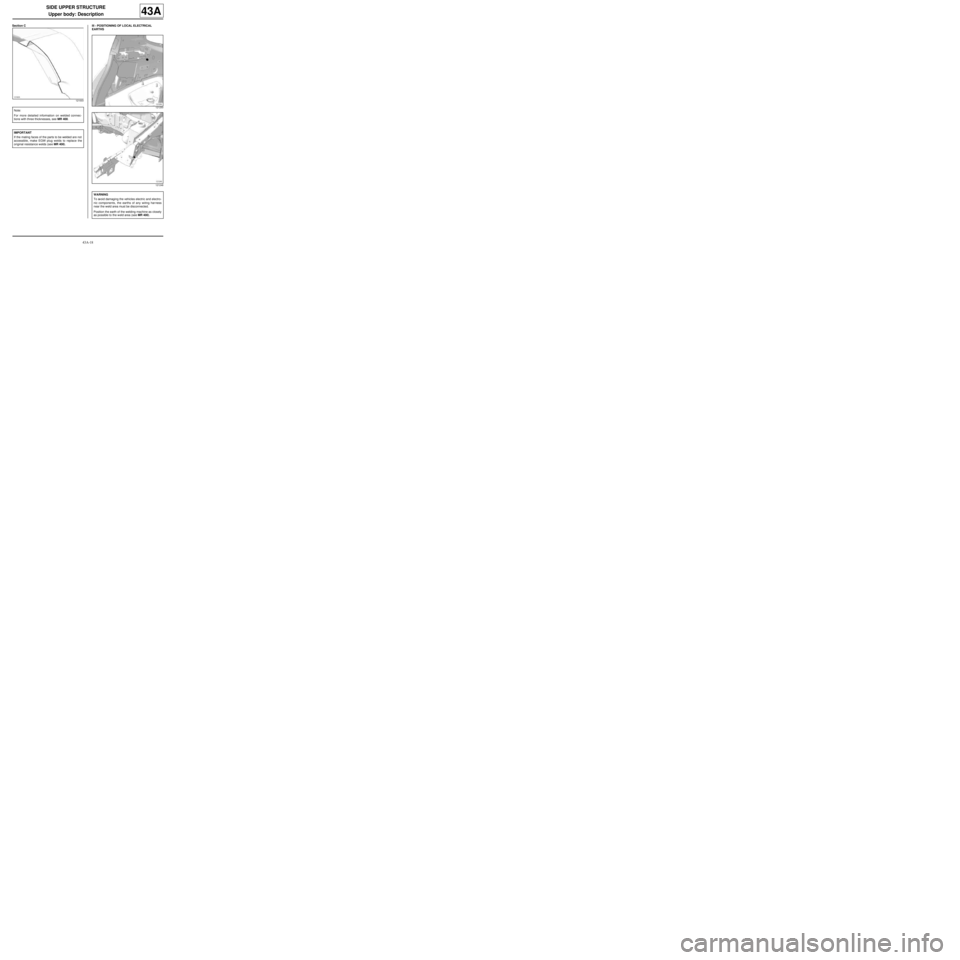
Section C III - POSITIONING OF LOCAL ELECTRICAL
EARTHS
121003
Note:
For more detailed information on welded connec-
tions with three thicknesses, see MR 400.
IMPORTANT
If the mating faces of the parts to be welded are not
accessible, make EGW plug welds to replace the
original resistance welds (see MR 400).
121250
121248
WARNING
To avoid damaging the vehicles electric and electro-
nic components, the earths of any wiring harness
near the weld area must be disconnected.
Position the earth of the welding machine as closely
as possible to the weld area (see MR 400).
Page 156 of 209
44A-1
REAR UPPER STRUCTURE
Rear wing panel: General description
44A
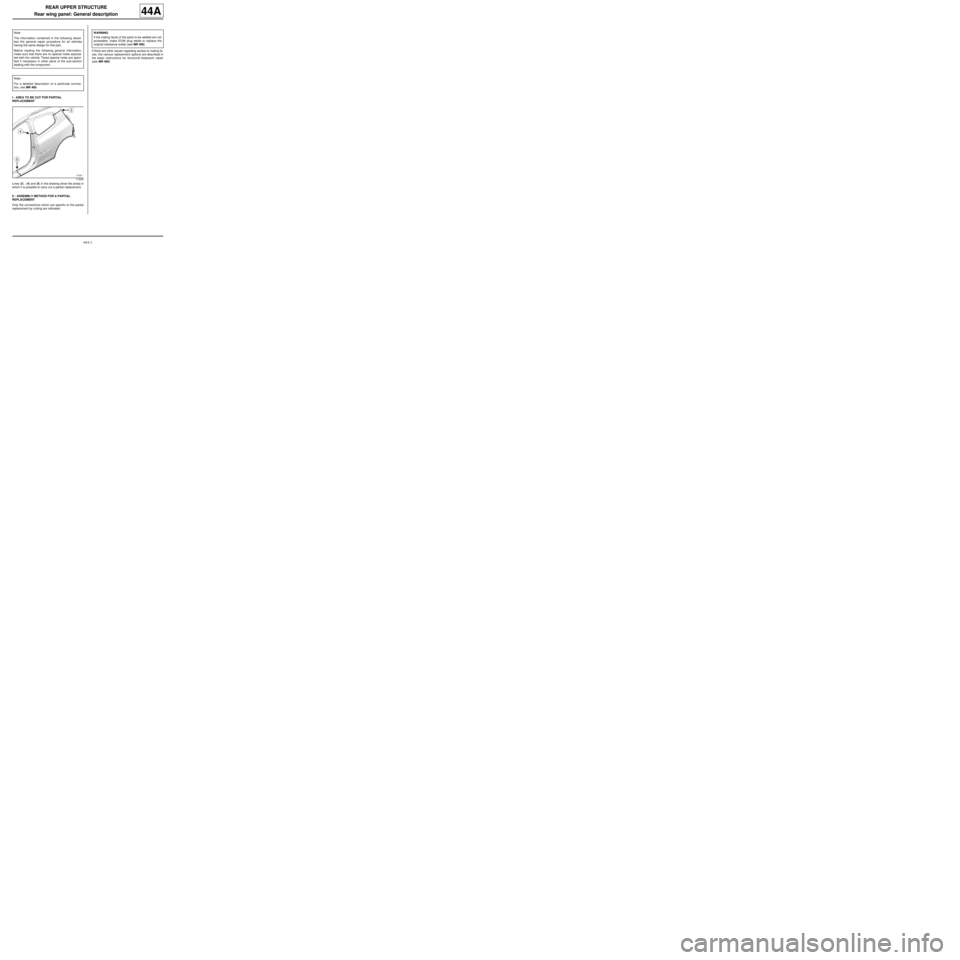
I - AREA TO BE CUT FOR PARTIAL
REPLACEMENT
Lines (3) , (4) and (5) in the drawing show the areas in
which it is possible to carry out a partial replacement.
II - ASSEMBLY METHOD FOR A PARTIAL
REPLACEMENT
Only the connections which are specific to the partial
replacement by cutting are indicated.If there are other issues regarding access to mating fa-
ces, the various replacement options are described in
the basic instructions for structural bodywork repair
(see MR 400). Note:
The information contained in the following descri-
bes the general repair procedure for all vehicles
having the same design for this part.
Before reading the following general information,
make sure that there are no special notes associa-
ted with the vehicle. These special notes are speci-
fied if necessary in other par ts of the sub-section
dealing with the component.
Note:
For a detailed description of a particular connec-
tion, see MR 400.
113208
WARNING
If the mating faces of the parts to be welded are not
accessible, make EGW plug welds to replace the
original resistance welds (see MR 400).
Page 159 of 209
44A-4
REAR UPPER STRUCTURE
Rear wing panel: Description
C44
44A
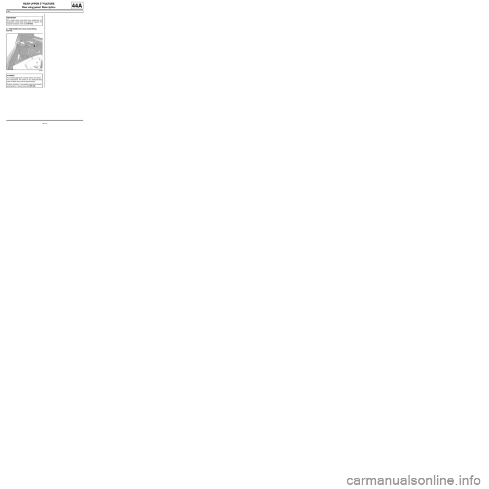
III - POSITIONING OF LOCAL ELECTRICAL
EARTHSIMPORTANT
If the mating faces of the parts to be welded are not
accessible, make EGW plug welds to replace the
original resistance welds (see MR 400).
121250
WARNING
To avoid damaging the vehicles electric and electro-
nic components, the earths of any wiring harness
near the weld area must be disconnected.
Position the earth of the welding machine as closely
as possible to the weld area (see MR 400).
Page 160 of 209
44A-5
REAR UPPER STRUCTURE
Rear lights mounting: General description
44A
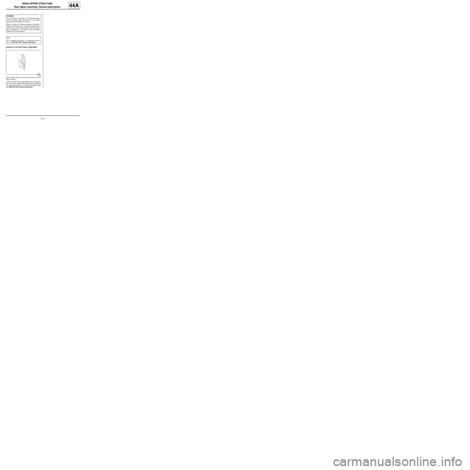
DESIGN OF THE STRUCTURAL COMPONENT
This is a basic part; its only function is that of a rear li-
ghts mounting.
If there are other issues regarding access to mating fa-
ces, the various replacement options are described in
the basic instructions for structural bodywork repair
(see MR 400, 40A, General Information). WARNING
The information contained in the following descri-
bes the general repair procedure for all vehicles
having the same design for this part.
Before reading the following general information,
make sure that there are no special notes associa-
ted with the vehicle. These special notes are speci-
fied if necessary in other par ts of the sub-section
dealing with the component.
Note:
For a detailed description of a particular connec-
tion, see MR 400, 40A, General Information.
109669
Page 162 of 209
44A-7
REAR UPPER STRUCTURE
Rear lights mounting: Description
C44
44A
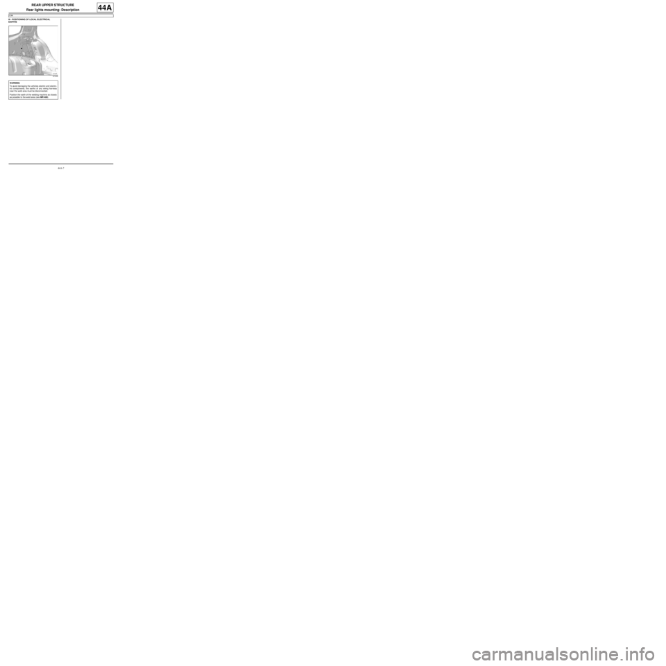
III - POSITIONING OF LOCAL ELECTRICAL
EARTHS
121249
WARNING
To avoid damaging the vehicles electric and electro-
nic components, the earths of any wiring harness
near the weld area must be disconnected.
Position the earth of the welding machine as closely
as possible to the weld area (see MR 400).
Page 163 of 209
44A-8
REAR UPPER STRUCTURE
Outer rear wheel arch: General description
44A
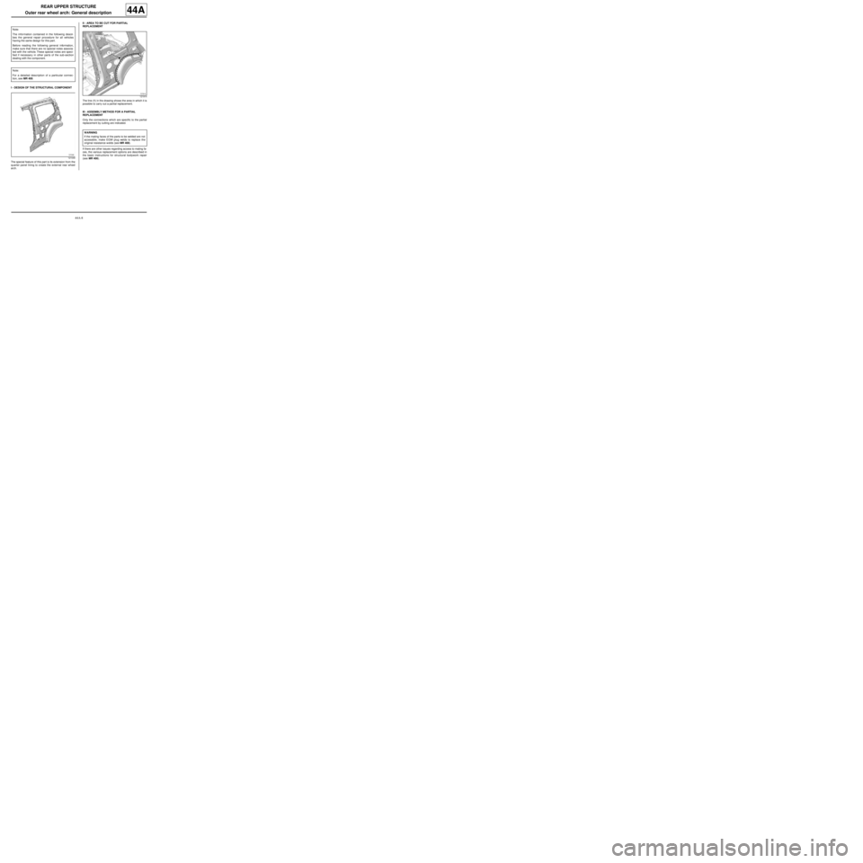
I - DESIGN OF THE STRUCTURAL COMPONENT
The special feature of this part is its extension from the
quarter panel lining to create the external rear wheel
arch.II - AREA TO BE CUT FOR PARTIAL
REPLACEMENT
The line (1) in the drawing shows the area in which it is
possible to carry out a partial replacement.
III - ASSEMBLY METHOD FOR A PARTIAL
REPLACEMENT
Only the connections which are specific to the partial
replacement by cutting are indicated.
If there are other issues regarding access to mating fa-
ces, the various replacement options are described in
the basic instructions for structural bodywork repair
(see MR 400). Note:
The information contained in the following descri-
bes the general repair procedure for all vehicles
having the same design for this part.
Before reading the following general information,
make sure that there are no special notes associa-
ted with the vehicle. These special notes are speci-
fied if necessary in other par ts of the sub-section
dealing with the component.
Note:
For a detailed description of a particular connec-
tion, see MR 400.
121049
121914
WARNING
If the mating faces of the parts to be welded are not
accessible, make EGW plug welds to replace the
original resistance welds (see MR 400).
Page 167 of 209
44A-12
REAR UPPER STRUCTURE
Outer rear wheel arch: Description
44A
III - POSITIONING OF LOCAL ELECTRICAL
EARTHS
121250
WARNING
To avoid damaging the vehicles electric and electro-
nic components, the earths of any wiring harness
near the weld area must be disconnected.
Position the earth of the welding machine as closely
as possible to the weld area (see MR 400).
Page 170 of 209
44A-15
REAR UPPER STRUCTURE
Inner rear wheel arch: Description
44A
III - POSITIONING OF LOCAL ELECTRICAL
EARTHS
121250
WARNING
To avoid damaging the vehicles electric and electro-
nic components, the earths of any wiring harness
near the weld area must be disconnected.
Position the earth of the welding machine as closely
as possible to the weld area (see MR 400).