warning RENAULT TWINGO RS 2009 2.G Chasiss Owner's Manual
[x] Cancel search | Manufacturer: RENAULT, Model Year: 2009, Model line: TWINGO RS, Model: RENAULT TWINGO RS 2009 2.GPages: 281
Page 71 of 281

31A-28
FRONT AXLE COMPONENTS
Front hub carrier bearing: Removal - Refitting
31A
II - REFITTING OPERATION FOR PART
CONCERNED
aRefit the bearing using a hydraulic press, taking hold
of the outer bush with a pipe with an outer diame-
ter of 70 mm (8) .
aRefit the circlip.aRefit the hub (9) using a hydraulic press, taking hold
of the bearing's internal bush with a pipe with an
outer diameter of 50 mm (10) .
III - FINAL OPERATION.
aRefit:
-the front driveshaft hub carrier (see 31A, Front
axle components, Front driveshaft hub carrier:
Removal - Refitting, page 31A-23) ,
-the brake disc (see 31A, Front axle components,
Front brake disc: Removal - Refitting, page 31A-
19) ,
-the calliper mounting (see 31A, Front axle com-
ponents, Front brake calliper mounting: Re-
moval - Refitting, page 31A-14) ,
-the front brake pads (see 31A, Front axle compo-
nents, Front brake pads: Removal - Refitting,
page 31A-1) ,
-the front wheel on the side in question (see 35A,
Wheels and tyres, Wheel: Removal - Refitting,
page 35A-1) .
114182
WARNING
Do not press the bearing's inner bush so as to
avoid damaging the bearing (very high shrink-fit-
ting force).
Note:
the black side of the bearing must be fitted on the
circlip side.
114183
Page 74 of 281
31A-31
FRONT AXLE COMPONENTS
Front shock absorber and spring: Removal - Refitting31A
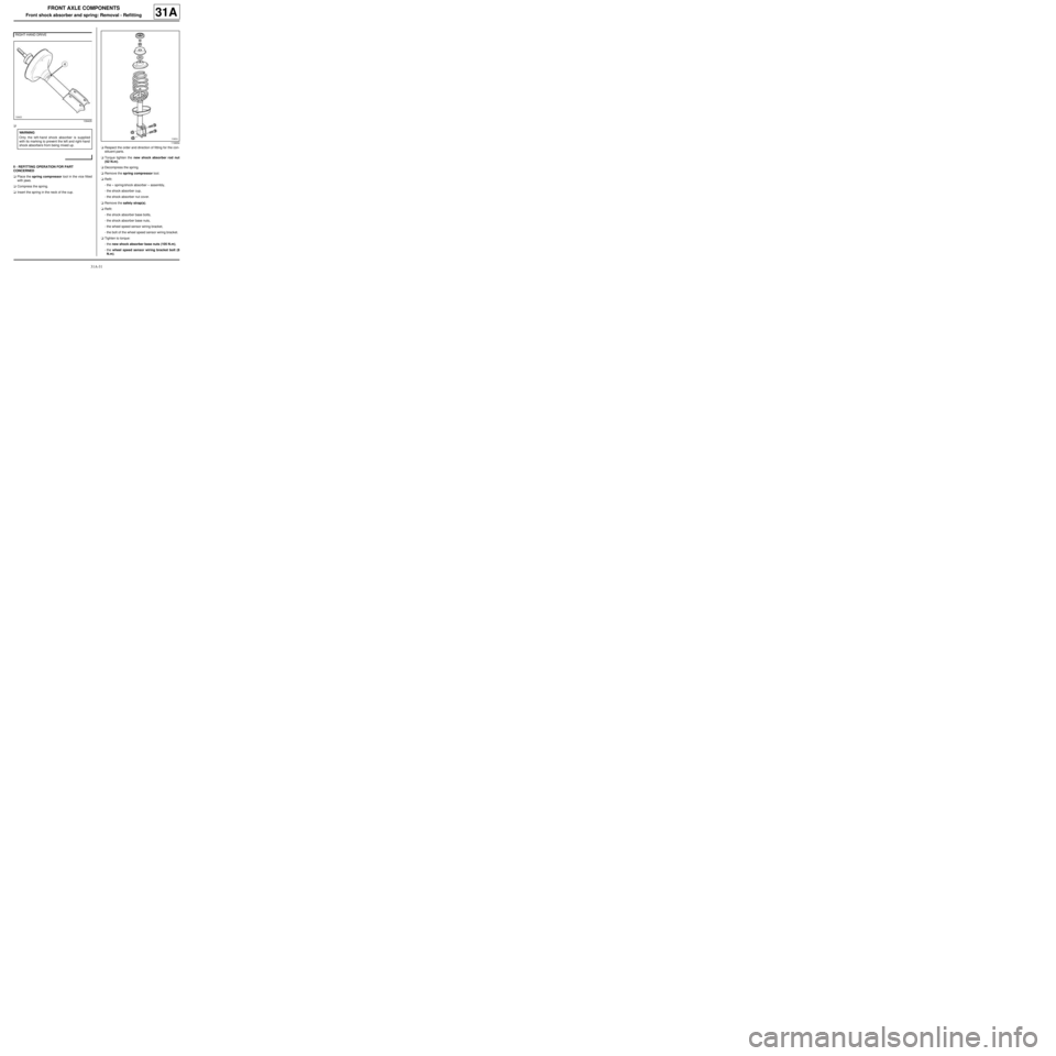
a
II - REFITTING OPERATION FOR PART
CONCERNED
aPlace the spring compressor tool in the vice fitted
with jaws.
aCompress the spring.
aInsert the spring in the neck of the cup.aRespect the order and direction of fitting for the con-
stituent parts.
aTorque tighten the new shock absorber rod nut
(62 N.m).
aDecompress the spring.
aRemove the spring compressor tool.
aRefit:
-the « spring/shock absorber » assembly,
-the shock absorber cup,
-the shock absorber nut cover.
aRemove the safety strap(s).
aRefit:
-the shock absorber base bolts,
-the shock absorber base nuts,
-the wheel speed sensor wiring bracket,
-the bolt of the wheel speed sensor wiring bracket.
aTighten to torque:
-the new shock absorber base nuts (105 N.m),
-the wheel speed sensor wiring bracket bolt (8
N.m). RIGHT-HAND DRIVE
139405
WARNING
Only the left-hand shock absorber is supplied
with its marking to prevent the left and right-hand
shock absorbers from being mixed up.
119654
Page 77 of 281
31A-34
FRONT AXLE COMPONENTS
Front driveshaft lower arm: Removal - Refitting
EQ UIPMENT LEVEL EA0 or EQUIPMENT LEVEL EA1 or EQUIPMENT LEVEL EA3 or EQUIPMENT LEVEL EA5
or EQUIPMENT LEVEL EAG or EQUIPMENT LEVEL EZ2 or EQUIPMENT LEVEL EZ4
31A
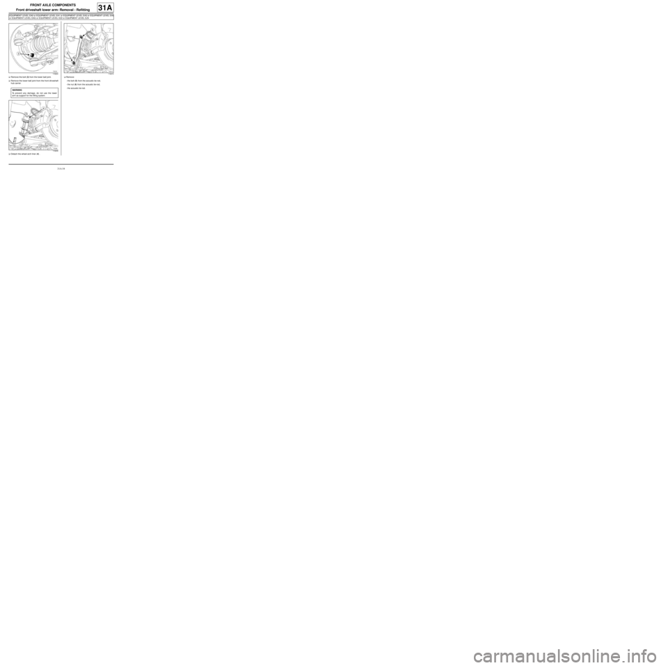
aRemove the bolt (3) from the lower ball joint.
aRemove the lower ball joint from the front driveshaft
hub carrier.
aDetach the wheel arch liner (4) .aRemove:
-the bolt (5) from the acoustic tie-rod,
-the nut (6) from the acoustic tie-rod,
-the acoustic tie-rod.
119224
WARNING
To prevent any damage, do not use the lower
arm as support for the lifting system.
119209
119210
Page 78 of 281
31A-35
FRONT AXLE COMPONENTS
Front driveshaft lower arm: Removal - Refitting
EQ UIPMENT LEVEL EA0 or EQUIPMENT LEVEL EA1 or EQUIPMENT LEVEL EA3 or EQUIPMENT LEVEL EA5
or EQUIPMENT LEVEL EAG or EQUIPMENT LEVEL EZ2 or EQUIPMENT LEVEL EZ4
31A
II - OPERATION FOR REMOVAL OF PART
CONCERNED
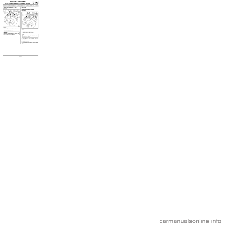
aRemove:
-the bolts (7) from the front driveshaft lower arm,
-the front driveshaft lower arm.REFITTING
I - REFITTING OPERATION FOR PART
CONCERNED
aRefit:
-the front driveshaft lower arm,
-the front driveshaft lower arm bolts.
aTorque tighten the front driveshaft lower arm
bolts (105 Nm).
II - FINAL OPERATION.
aFit the lower ball joint on the front driveshaft hub car-
rier.
119344
WARNING
To prevent any damage, do not use the lower
arm as support for the lifting system.
119344
Note:
Obser ve the direction of fitting for the front drive-
shaft lo wer arm bolts (7) .
Page 81 of 281
31A-38
FRONT AXLE COMPONENTS
Front driveshaft lower arm: Removal - Refitting
EQ UIPMENT LEVEL SPORT
31A
II - OPERATION FOR REMOVAL OF PART
CONCERNED
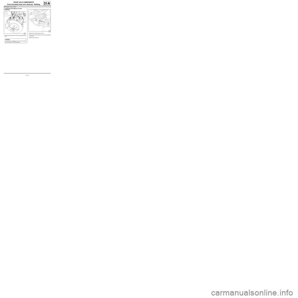
aRemove the studs (4) from the front driveshaft lower
arm.aRemove the lower ball joint nut (5) .
aRemove the lower ball joint from the front driveshaft
hub carrier.
aRemove the lower arm.
119344
WARNING
To prevent any damage, do not use the lower
arm as support for the lifting system.
132460
Page 84 of 281
31A-41
FRONT AXLE COMPONENTS
Front driveshaft lower arm ball joint: Removal - Refitting31A
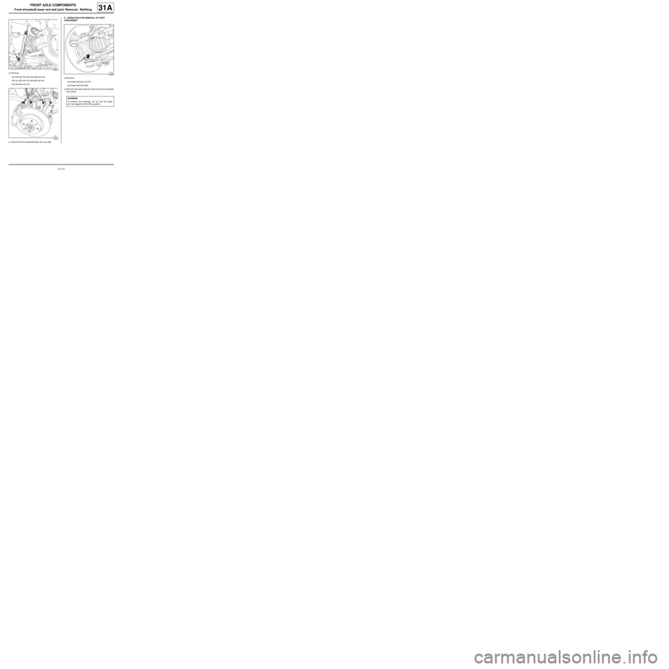
aRemove:
-the bolt (4) from the acoustic tie-rod,
-the nut (5) from the acoustic tie-rod,
-the acoustic tie-rod.
aUndo the front driveshaft lower arm nuts (6) .II - OPERATION FOR REMOVAL OF PART
CONCERNED
aRemove:
-the lower ball joint nut (7) ,
-the lower ball joint bolt.
aRemove the lower ball joint from the front driveshaft
hub carrier.
119210
119344
119224
WARNING
To prevent any damage, do not use the lower
ar m as support for the lifting system.
Page 99 of 281
33A-1
REAR AXLE COMPONENTS
Rear brake pads: Removal - Refitting
EQ UIPMENT LEVEL SPORT
33A
When replacing brake pads, be sure to replace the
pads on the opposite side.
REMOVAL
I - REMOVAL PREPARATION OPERATION
aPosition the vehicle on a two-post lift (see Vehicle:
Towing and lifting) (02A, Lifting equipment).
aRelease the parking brake.
aRemove the rear wheels (see 35A, Wheels and ty-
res, Wheel: Removal - Refitting, page 35A-1) .II - OPERATION FOR REMOVAL OF PART
CONCERNED
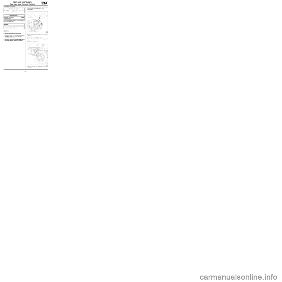
aUnclip the parking brake cable from the brake calli-
per at (1) .
aMove aside the parking brake cable.
aRemove the lower bolt (2) of the brake calliper guide
pin.
aTilt the brake calliper over.
aRemove the brake pads (3) from the brake calliper
mounting. Special tooling required
Fre. 1190-01Brake calliper piston return
tool.
Tightening torquesm
new lower bolts of the
calliper guide pins35 N.m
WARNING
To avoid damaging the parking brake cable protec-
tors and causing premature wear of the system, do
not handle the cables with a tool.
132468
132466
Page 102 of 281
33A-4
REAR AXLE COMPONENTS
Rear brake hose: Removal - Refitting
33A
REMOVAL
I - REMOVAL PREPARATION OPERATION
aPosition the vehicle on a two-post lift ( (see Vehicle:
Towing and lifting) ).
aFit the pedal press to the brake pedal to limit the
outflow of brake fluid.
II - OPERATION FOR REMOVAL OF PART
CONCERNED
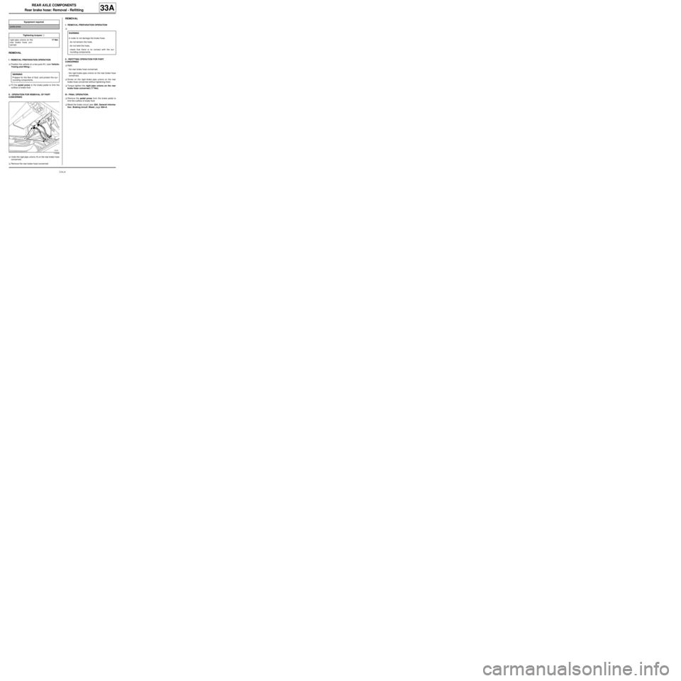
aUndo the rigid pipe unions (1) on the rear brake hose
concerned.
aRemove the rear brake hose concerned.
REMOVAL
I - REMOVAL PREPARATION OPERATION
a
II - REFITTING OPERATION FOR PART
CONCERNED
aRefit:
-the rear brake hose concerned,
-the rigid brake pipe unions on the rear brake hose
concerned.
aScrew on the rigid brake pipe unions on the rear
brake hose concerned without tightening them.
aTorque tighten the rigid pipe unions on the rear
brake hose concerned ( 17 Nm).
III - FINAL OPERATION.
aRemove the pedal press from the brake pedal to
limit the outflow of brake fluid.
aBleed the brake circuit (see 30A, General informa-
tion, Braking circuit: Bleed, page 30A-4) . Equipment requiredpedal press
Tightening torquesm
rigid pipe unions on the
rear brake hose con-
cerned17 Nm
WARNING
Prepare for the flow of fluid, and protect the sur-
rounding components.
119339
WARNING
In order to not damage the brake hose:
-do not tension the hose,
-do not twist the hose,
-check that there is no contact with the sur-
rounding components.
Page 103 of 281
33A-5
REAR AXLE COMPONENTS
Rear brake hose: Removal - Refitting
EQ UIPMENT LEVEL SPORT
33A
REMOVAL
I - REMOVAL PREPARATION OPERATION
aPosition the vehicle on a two-post lift (see Vehicle:
Towing and lifting) (02A, Lifting equipment).
aPosition a pedal press on the brake pedal to limit
the outflow of brake fluid.II - OPERATION FOR REMOVAL OF PART
CONCERNED
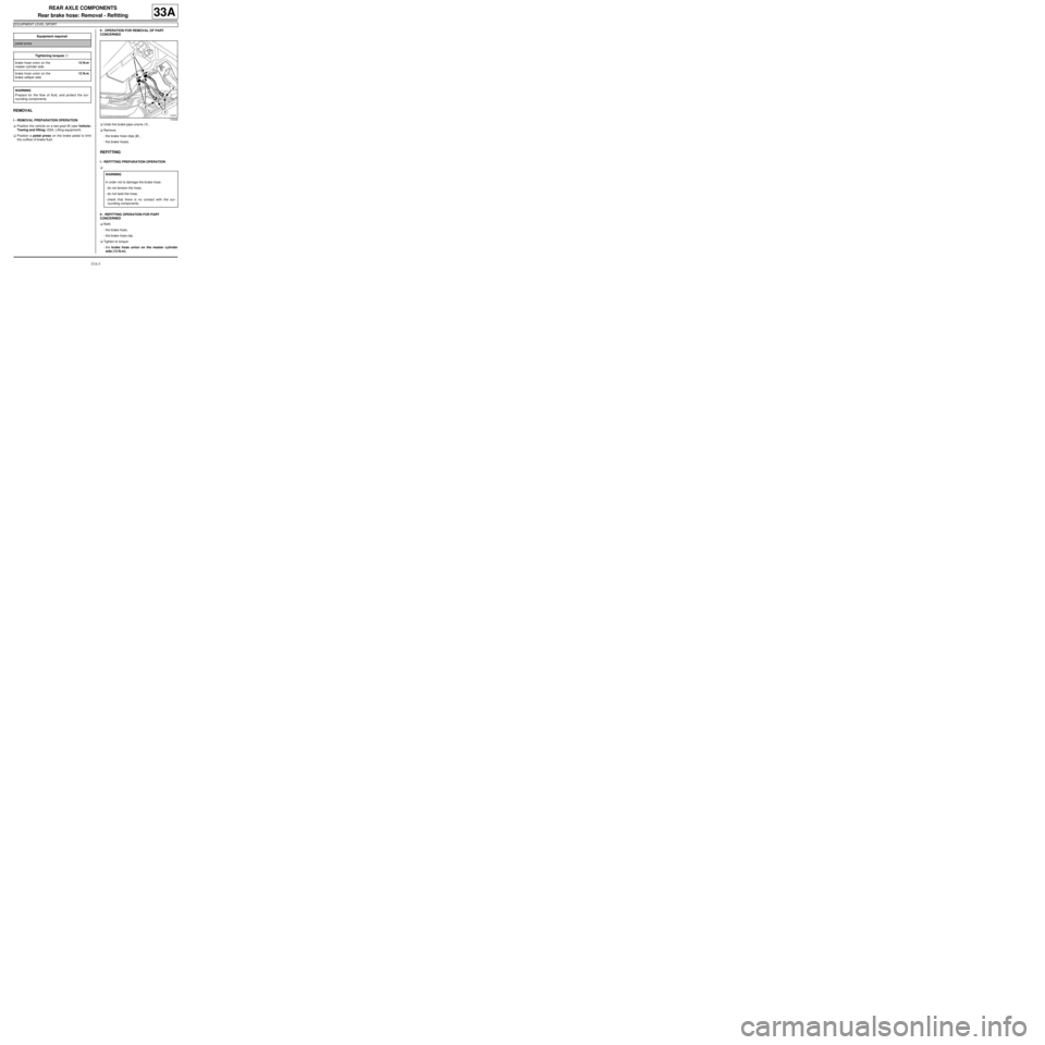
aUndo the brake pipe unions (1) .
aRemove:
-the brake hose clips (2) ,
-the brake hoses.
REFITTING
I - REFITTING PREPARATION OPERATION
a
II - REFITTING OPERATION FOR PART
CONCERNED
aRefit:
-the brake hose,
-the brake hose clip.
aTighten to torque:
-the brake hose union on the master cylinder
side (13 N.m), Equipment required
pedal press
Tightening torquesm
brake hose union on the
master cylinder side13 N.m
brake hose union on the
brake calliper side13 N.m
WARNING
Prepare for the flow of fluid, and protect the sur-
rounding components.
119339
WARNING
In order not to damage the brake hose:
-do not tension the hose,
-do not twist the hose,
-check that there is no contact with the sur-
rounding components.
Page 105 of 281

33A-7
REAR AXLE COMPONENTS
Rear brake calliper: Removal - Refitting
EQ UIPMENT LEVEL SPORT
33A
REMOVAL
I - REMOVAL PREPARATION OPERATION
aPosition the vehicle on a two-post lift (see Vehicle:
Towing and lifting) (02A, Lifting equipment).
aRelease the parking brake.
aPosition a pedal press on the brake pedal to limit
the outflow of brake fluid.
aRemove the rear wheel (see 35A, Wheels and ty-
res, Wheel: Removal - Refitting, page 35A-1) .II - OPERATION FOR REMOVAL OF PART
CONCERNED
aUnclip the parking brake cable from the brake calli-
per at (1) .
aMove aside the parking brake cable.
aLoosen the calliper brake pipe union (2) .
aRemove:
-the brake calliper guide pin bolts (3) ,
-the brake calliper from the mounting,
-the union between the brake pipe and the calliper,
-the brake calliper.
REFITTING
I - REFITTING PREPARATION OPERATION
aClean using a wire brush and BRAKE CLEANER
(see Vehicle: Parts and consumables for the re-
pair) (04B, Consumables - Products):
-the calliper supports,
-the callipers.
aAlways replace the brake calliper guide pin bolts. Special tooling required
Fre. 1190-01Brake calliper piston return
tool.
Equipment required
pedal press
Tightening torquesm
new bolts on the brake
calliper guide pins35 N.m
brake pipe union on the
calliper13 N.m
WARNING
To avoid damaging the parking brake cable protec-
tors and causing premature wear of the system, do
not handle the cables with a tool.
132468