camshaft RENAULT TWINGO RS 2009 2.G Engine And Peripherals Owner's Manual
[x] Cancel search | Manufacturer: RENAULT, Model Year: 2009, Model line: TWINGO RS, Model: RENAULT TWINGO RS 2009 2.GPages: 652
Page 174 of 652
11A-57
TOP AND FRONT OF ENGINE
Timing belt: Removal - Refitting
K4M
11A
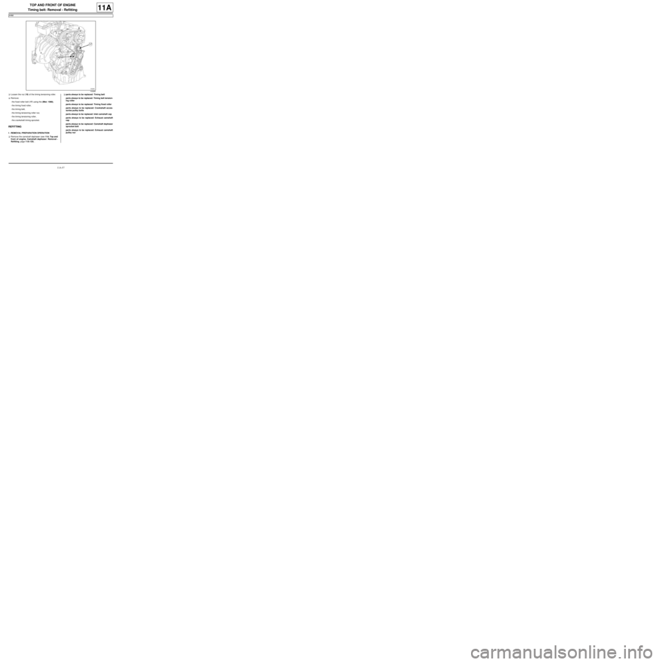
aLoosen the nut (16) of the timing tensioning roller.
aRemove:
-the fixed roller bolt (17) using the (Mot. 1368),
-the timing fixed roller,
-the timing belt,
-the timing tensioning roller nut,
-the timing tensioning roller,
-the crankshaft timing sprocket.
REFITTING
I - REMOVAL PREPARATION OPERATION
aRemove the camshaft dephaser (see 11A, Top and
front of engine, Camshaft dephaser: Removal -
Refitting, page 11A-135) .aparts always to be replaced: Timing belt
parts always to be replaced: Timing belt tension-
ing roller
parts always to be replaced: Timing fixed roller
parts always to be replaced: Crankshaft acces-
sories pulley bolts
parts always to be replaced: Inlet camshaft cap
parts always to be replaced: Exhaust camshaft
cap
parts always to be replaced: Camshaft dephaser
sprocket bolt
parts always to be replaced: Exhaust camshaft
pulley nut
103268
Page 175 of 652
11A-58
TOP AND FRONT OF ENGINE
Timing belt: Removal - Refitting
K4M
11A
II - REFITTING OPERATION
1 - Adjusting the timing
a
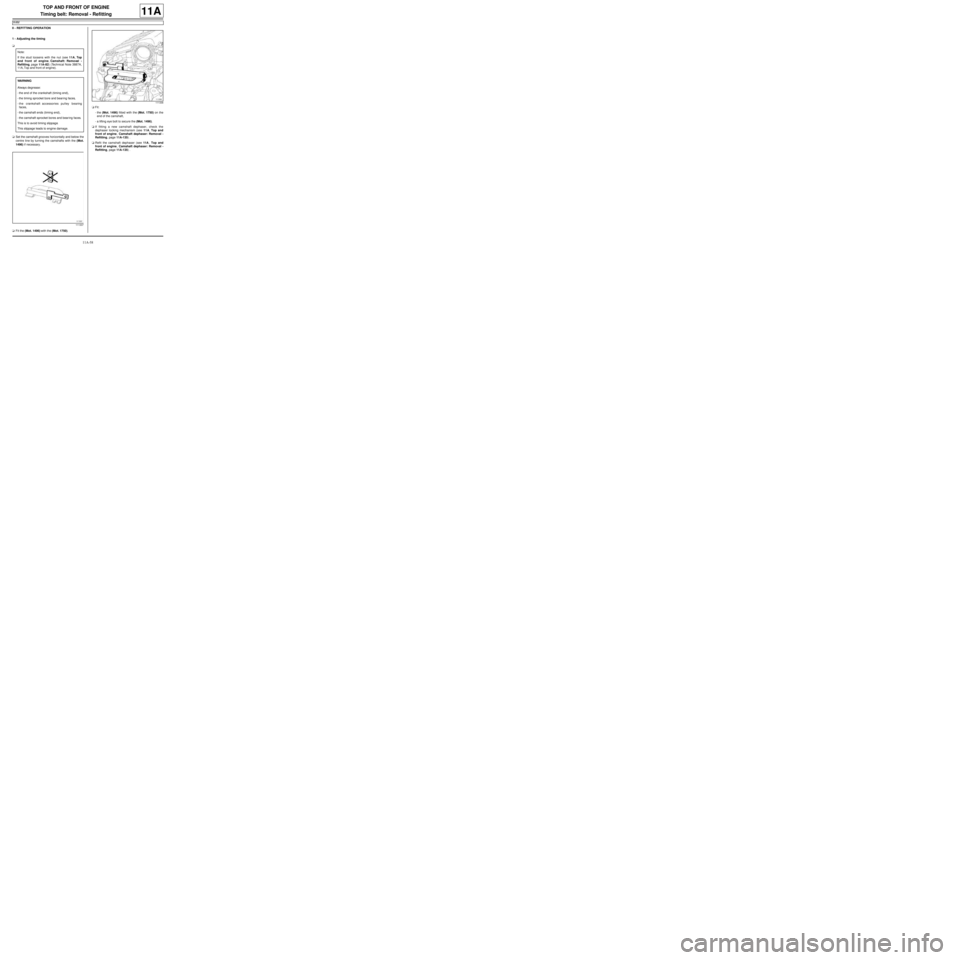
aSet the camshaft grooves horizontally and below the
centre line by turning the camshafts with the (Mot.
1496) if necessary.
aFit the (Mot. 1496) with the (Mot. 1750).aFit:
-the (Mot. 1496) fitted with the (Mot. 1750) on the
end of the camshaft,
-a lifting eye bolt to secure the (Mot. 1496).
aIf fitting a new camshaft dephaser, check the
dephaser locking mechanism (see 11A, Top and
front of engine, Camshaft dephaser: Removal -
Refitting, page 11A-135) .
aRefit the camshaft dephaser (see 11A, Top and
front of engine, Camshaft dephaser: Removal -
Refitting, page 11A-135) . Note:
If the stud loosens with the nut (see 11A, Top
and front of engine, Camshaft: Removal -
Refitting, page 11A-82) (Technical Note 3887A,
11A, Top and front of engine).
WARNING
Always degrease:
-the end of the crankshaft (timing end),
-the timing sprocket bore and bear ing faces,
-the crankshaft accessories pulley bearing
faces,
-the camshaft ends (timing end),
-the camshaft sprocket bores and bear ing faces.
This is to avoid timing slippage.
This slippage leads to engine damage.
111337
111336
Page 176 of 652
11A-59
TOP AND FRONT OF ENGINE
Timing belt: Removal - Refitting
K4M
11A
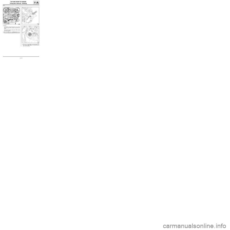
aPosition:
-the RENAULT badge (18) etched on the exhaust
camshaft pulley stem vertically and pointing up-
wards,
-the camshaft dephaser pulley mark (19) vertically
and facing upwards.
aMake a mark (20) using a indelible pencil between
the camshaft dephaser pulley and the rocker cover.
aCheck that the crankshaft is pressing against the
TDC setting pin (Mot. 1489). The crankshaft groove
(21) must be upwards.
13049214489
132387
Page 177 of 652
11A-60
TOP AND FRONT OF ENGINE
Timing belt: Removal - Refitting
K4M
11A
2 - Refitting the timing belt
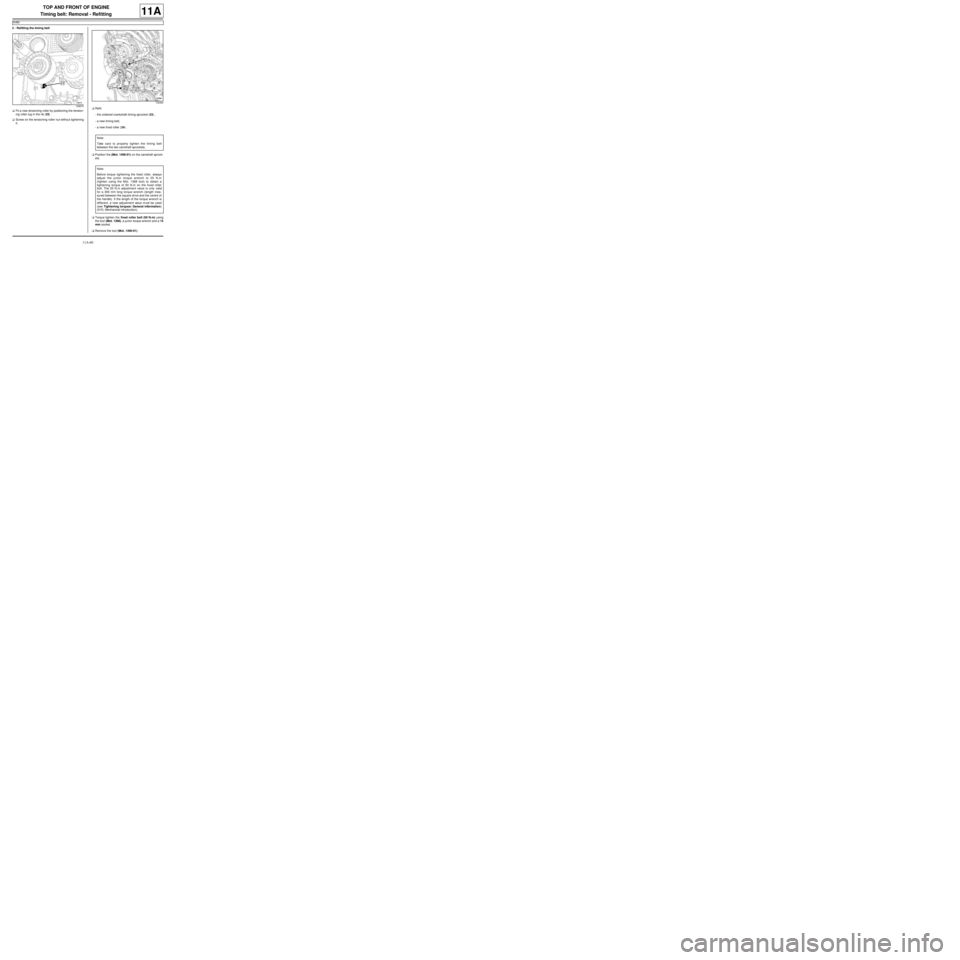
aFit a new tensioning roller by positioning the tension-
ing roller lug in the rib (22) .
aScrew on the tensioning roller nut without tightening
it.aRefit:
-the cottered crankshaft timing sprocket (23) ,
-a new timing belt,
-a new fixed roller (24) .
aPosition the (Mot. 1490-01) on the camshaft sprock-
ets.
aTorque tighten the fixed roller bolt (50 N.m) using
the tool (Mot. 1368), a junior torque wrench and a 15
mm socket.
aRemove the tool (Mot. 1490-01).
108879
132384
Note:
Take care to properly tighten the timing belt
between the two camshaft sprockets.
Note:
Before torque tightening the fixed roller, always
adjust the junior torque wrench to 25 N.m
(tighten using the Mot. 1368 tool) to obtain a
tightening torque of 50 N.m on the fixed roller
bolt. The 25 N.m adjustment value is only valid
for a 300 mm long torque wrench (length mea-
sured between the square dr ive and the centre of
the handle). If the length of the torque wrench is
different, a new adjustment value m ust be used
(see Tightening torques: General information)
(01D, Mechanical introduction).
Page 179 of 652
11A-62
TOP AND FRONT OF ENGINE
Timing belt: Removal - Refitting
K4M
11A
aPosition the (Mot. 1490-01) (30) on the camshaft
pulleys.
aTorque tighten:
-and angle tighten the exhaust camshaft pulley
nut (30 N.m + 84˚),
-the camshaft dephaser pulley bolt (100 N.m).
aRefit the dephaser pulley bolt cover.
aRemove:
-the timing flap from the lower timing cover,
-the (Mot. 1496),-the TDC setting pin (Mot. 1489),
-the (Mot. 1490-01).
4 - Checking the tension
aRotate the crankshaft twice in a clockwise direction,
on the timing end, before aligning the marks (on the
camshaft dephaser) already made by the operator.
aScrew in the TDC setting pin (Mot. 1489).
aMove the crankshaft slowly and smoothly to rest on
the TDC setting pin.
aRemove the TDC setting pin (Mot. 1489).
103265
109052
Page 180 of 652
11A-63
TOP AND FRONT OF ENGINE
Timing belt: Removal - Refitting
K4M
11A
aCheck through the lower timing cover window that
the adjustable index (31) is opposite the notch (32) ,
if this is not the case:
-loosen the timing tensioning roller nut by up to one
turn while holding the eccentric with a 6 mm Allen
key,
-gradually move the adjustable index marker (31)
opposite the mark (32) turning the eccentric cam
(33) clockwise.
aTorque tighten the timing tension wheel nut (27
N.m).5 - Checking the timing
aEnsure that the index and the notch on the timing
tensioning roller are in the correct position before
checking the timing.
aScrew in the TDC setting pin (Mot. 1489).
aBring the crankshaft slowly and smoothly to rest
against the TDC setting pin (Mot. 1489).
aPosition (without forcing) the camshaft setting tool
(Mot. 1496) fitted with the (Mot. 1750) (the camshaft
end grooves must be horizontal and offset towards
the bottom).
aRemove:
-the timing tool (Mot. 1496) fitted with the (Mot.
1750),
-the TDC setting pin (Mot. 1489).
109051
103263
14490
Note:
The timing adjustment and tensioning operation
must be repeated if the camshaft setting tool
does not engage .
Page 181 of 652
11A-64
TOP AND FRONT OF ENGINE
Timing belt: Removal - Refitting
K4M
11A
aRefit the lower timing cover flap, checking that the
locating pin (34) fits properly in the notch (35) .
III - FINAL OPERATION
aRefit:
-a new inlet camshaft plug using the (Mot. 1487),
-a new exhaust camshaft plug using the (Mot.
1488),
-the lifting eye.
aClip the wiring onto the lifting eye.aPlace a drop of SILICONE ADHESIVE SEALANT
(see Vehicle: Parts and consumables for the re-
pair) (04B, Consumables - Products) on the thread
of the TDC setting pin plug.
aTorque tighten the TDC setting pin plug (20 N.m).
aRefit the upper timing cover.
aTorque tighten:
-the upper timing cover bolts (41 N.m),
-the upper timing cover nuts (41 N.m).
aPosition the wiring of the upstream oxygen sensor.
aAttach the upstream oxygen sensor wiring.
aConnect the upstream oxygen sensor connector.
aRefit:
-the right-hand suspended engine mounting (see
19D, Engine mounting, Right-hand suspended
engine mounting: Removal - Refitting, page
19D-13) ,
-the rear suspended engine mounting.
aTorque tighten:
-the rear suspended engine reinforcement bolt
(105 N.m),
-the rear suspended engine mounting bolt on
the rear suspended engine mounting support
(105 N.m),
-the rear suspended engine mounting bolt on
the subframe (105 N.m).
aRefit:
-the scoop under the scuttle panel grille (see Scoop
under the scuttle panel grille: Removal - Refit-
ting) (56A, Exterior equipment),
-the scuttle panel grille (see Scuttle panel grille:
Removal - Refitting) (56A, Exterior equipment),
-the windscreen wiper arms (see Windscreen wip-
er arm: Removal - Refitting) (85A, Wiping -
Washing),
-the throttle valve (see 12A, Fuel mixture, Throttle
valve: Removal - Refitting, page 12A-20) ,
-the air filter unit (see 12A, Fuel mixture, Air filter
unit: Removal - Refitting, page 12A-13) ,
-the accessories belt (see 11A, Top and front of
engine, Accessories belt: Removal - Refitting,
page 11A-3) ,
-the front upper cross member (see Front upper
cross member: Removal - Refitting) (42A, Upper
front structure),
109052
14890
Page 187 of 652
11A-70
TOP AND FRONT OF ENGINE
Rocker cover: Removal - Refitting
D4F, and 772
11A
II - REFITTING OPERATION FOR PART
CONCERNED
aApply a bead (1) of SILICONE ADHESIVE SEAL-
ANT (see Vehicle: Parts and consumables for
the repair) (04B, Consumables - Products) to the
camshaft bearings 1 and 5, as well as around the
rocker cover rear bolts.
aFit the rocker cover with a new gasket.aTighten the rocker cover bolts in order.
III - FINAL OPERATION
aRefit:
-the ignition coil (see 17A, Ignition, Coils: Remov-
al - Refitting, page 17A-1) ,
-the inlet distributor (see 12A, Fuel mixture, Inlet
distributor: Removal - Refitting, page 12A-29) ,
-the air filter unit (see 12A, Fuel mixture, Air filter
unit: Removal - Refitting, page 12A-13) .
aClip on the rocker cover electric wiring harnesses.
aConnect the battery (see Battery: Removal - Refit-
ting) (80A, Battery).
18441
20005
110422
Page 191 of 652
11A-74
TOP AND FRONT OF ENGINE
Rocker cover: Removal - Refitting
D4F, and 780 or 782 or 784
11A
II - REFITTING OPERATION FOR PART
CONCERNED
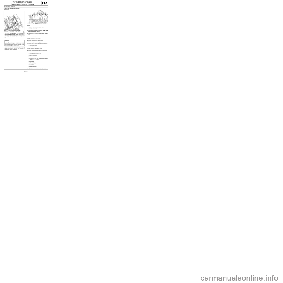
aApply beads (1) of MASTIXO (see Vehicle: Parts
and consumables for the repair) (04B, Consum-
ables - Products) around the rocker cover rear bolts
(lower bolts, exhaust side) and on camshaft bearing
no.5.
aFit the new rocker cover seal, starting with bearing
No. 5, then gradually insert the seal studs as the
rocker cover fits into the groove.aRefit:
-the rocker cover fitted with a new seal,
-the rocker cover bolts.
aPretighten to torque and in order the rocker cover
bolts (initial torque) (5 N.m).
aTorque tighten in order the rocker cover bolts (13
N.m).
III - FINAL OPERATION
aFit the brake servo vacuum pipe.
aConnect the brake servo vacuum pipe.
aFit the fuel vapour rebreathing pipes.
aConnect the fuel vapour rebreathing circuit unions:
-on the inlet distributor,
-on the air filter box outlet air pipe.
aFit the oil vapour rebreathing circuit.
aConnect the oil vapour rebreathing circuit unions:
-on the rocker cover,
-on the air filter box outlet air pipe,
-to the inlet distributor.
aRefit:
-the ignition coil (see 17A, Ignition, Coils: Remov-
al - Refitting, page 17A-1) ,
-the filler neck,
-the filler neck bolt,
-the heat shield,
-the heat shield bolts.
aTorque tighten the heat shield bolts (8 N.m).
18441
WARNING
Applying excess sealant could cause it to be
squeezed out when parts are tightened. A mix-
ture of sealant and fluid could damage certain
components (engine, radiator, etc.).
121026
Page 193 of 652
11A-76
TOP AND FRONT OF ENGINE
Rocker cover: Removal - Refitting
K4M
11A
REMOVAL
I - REMOVAL PREPARATION OPERATION
aPosition the vehicle on a two-post lift (see Vehicle:
Towing and lifting) (02A, Lifting equipment).
aDisconnect the battery (see Battery: Removal - Re-
fitting) (80A, Battery).
aRemove:
-the windscreen wiper arms (see Windscreen wip-
er arm: Removal - Refitting) (85A, Wiping -
Washing),
-the scuttle panel grille (see Scuttle panel grille:
Removal - Refitting) (56A, Exterior equipment),
-the scoop under the scuttle panel grille (see Scoop
under the scuttle panel grille: Removal - Refit-
ting) (56A, Exterior equipment),
-the coils (see 17A, Ignition, Coils: Removal - Re-
fitting, page 17A-1) ,
-the throttle valve (see 12A, Fuel mixture, Throttle
valve: Removal - Refitting, page 12A-20) ,
-the inlet distributor (see 12A, Fuel mixture, Inlet
distributor: Removal - Refitting, page 12A-29) ,
-the oil decanter (see 11A, Top and front of en-
gine, Oil decanter: Removal - Refitting, page
11A-147) ,
-the engine undertray,
-the front right-hand wheel (see Wheel: Removal -
Refitting) (35A, Wheels and tyres),
-the front right-hand wheel arch liner (see Front
wheel arch liner: Removal - Refitting) (55A, Ex-
terior protection),-the front bumper (see Front bumper: Removal -
Refitting) (55A, Exterior protection),
-the headlights (see Halogen headlight: Removal
- Refitting) (80B, Headlights),
-the bonnet catch (see Bonnet lock: Removal -
Refitting) (52A, Non-side opening element mecha-
nisms),
-the front upper cross member (see Front upper
cross member: Removal - Refitting) (42A, Upper
front structure),
-the accessories belt (see 11A, Top and front of
engine, Accessories belt: Removal - Refitting,
page 11A-3) ,
-the air filter unit (see 12A, Fuel mixture, Air filter
unit: Removal - Refitting, page 12A-13) ,
-the right-hand suspended engine mounting (see
19D, Engine mounting, Right-hand suspended
engine mounting: Removal - Refitting, page
19D-13) ,
-the crankshaft accessories pulley (see 11A, Top
and front of engine, Crankshaft accessories
pulley: Removal - Refitting, page 11A-20) ,
-the timing belt (see 11A, Top and front of engine,
Timing belt: Removal - Refitting, page 11A-27) ,
-the camshaft dephaser (see 11A, Top and front of
engine, Camshaft dephaser: Removal - Refit-
ting, page 11A-135) ,
-the camshaft seals on the timing end (see 11A,
Top and front of engine, Camshaft seal, timing
end: Removal - Refitting, page 11A-138) . Tightening torquesm
rocker cover bolts 22,
23, 20 and 13 (initial
torque)8 N.m
rocker cover bolts 1 to
12, 14 to 19 and 21 to
2413 N.m
rocker cover bolts 22,
23, 20 and 1313 N.m
camshaft sensor bolt8 N.m
camshaft dephaser
solenoid valve bolt10 N.m