gearbox Seat Ateca 2018 Service Manual
[x] Cancel search | Manufacturer: SEAT, Model Year: 2018, Model line: Ateca, Model: Seat Ateca 2018Pages: 348, PDF Size: 7.32 MB
Page 214 of 348
Operation
Automatically engaging and disengaging the
Aut o Ho
l
d function
If the Auto Hold function was switched on
with the button before disengaging the ig-
nition, the function will remain on after the
ignition is re-engaged.
If the Auto Hold function was not switched
on, it will automatically remain off next time
the ignition is engaged.
The Auto Hold function is automatically
switched on if the following conditions are
met:
All conditions must be met at the same time
››› :
Manual gearboxAutomatic gearbox
1.The vehicle is kept stationary with the brake ped-
al on a flat surface or on a slope.
2.The engine rotates “correctly”.
Upon pressing the
clutch and accelerating
at the same time, the
brake releases gradu-
ally.Upon accelerating, the
brake releases gradu-
ally. The Auto Hold function is automatically
t
urned off
if
the following conditions are
met:
Manual gearboxAutomatic gearbox
1.
If any of the conditions mentioned on
››› page 211, Conditions for keeping the vehicle
stationary with the Auto Hold function are no lon- ger met.
2.If the engine is running irregularly or an anomalyis detected.
3.If the engine is turnedoff or stalls.If the engine is switch- ed off.
4.The clutch and the ac-
celerator are pressed at the same time.If the accelerator is pressed.
5.
If any of the tyres hasonly minimal contact
with the ground, e.g. in the case of axle articu- lation. WARNING
The smart technology incorporated into the
Auto Ho l
d function cannot defy the laws of
physics; it only works within the limits of the
system. The greater convenience provided by
the Auto Hold function should never tempt
you to take any risk that may compromise
safety.
● Never leave the vehicle running and with
the Auto Hol
d function switched on. ●
The Auto Ho l
d function cannot always keep
the vehicle stationary uphill or downhill or
stop it sufficiently, for example, on slippery
or frozen surfaces. Note
Before entering a car wash, always switch off
the Aut o Hol
d function, because if the elec-
tronic parking brake is automatically connec-
ted, it may cause damage. Cruise control system (CCS)*
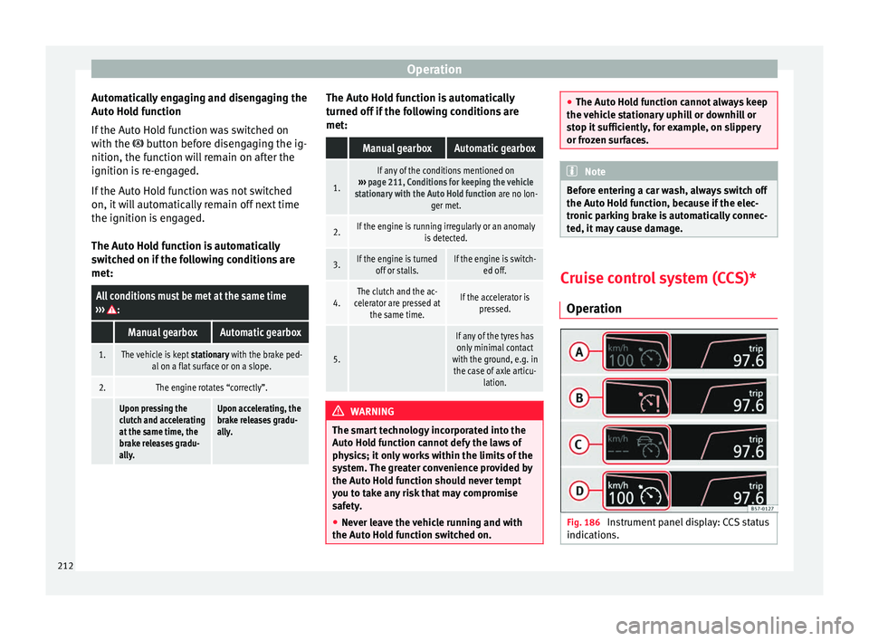
Oper ation Fig. 186
Instrument panel display: CCS status
indic ation s.212
Page 227 of 348
Driver assistance systems
Any modification to the programmed speed
w i
l
l be shown on the bottom left part of the
instrument panel display ››› Fig. 195.
Setting your distance level
To increase/reduce the distance level, press
the rocker switch towards the left/right
››› Fig. 198 A .
The in s
trument
panel display shows the mod-
ification of the distance level. There are 5 dis-
tance levels to choose from. SEAT recom-
mends level 3. The set distance can be
changed when the vehicle is stopped or dur-
ing driving, as you like ››› .
C onnectin
g and activ
ating the ACC
To connect and activate the ACC, the position
of the gearbox selector lever, the vehicle
speed and the position of the third level of
the ACC must all be taken into account.
● With a manual gearbox, the gearbox selec-
tor lev
er must be in any gear except first, and
speed must be greater than approximately 30
km/h. With an automatic gearbox, the gear-
box selector lever must be in position D or S.
● To activate the ACC, with the third lever in
position 1 press the
butt
on or mo
ve the
third lever of the ACC to position 2›››
Fig. 197. At thi s
point, the image of the
ACC on the instrument panel display will
switch to Active mode ››› Fig. 195. When the ACC function is active, the vehicle
trav
el
s at a set speed and distance from the
vehicle ahead. Both speed and distance can
be changed at any time.
Disconnecting and deactivating the ACC
To disconnect the ACC move the lever to the 0 position
›››
Fig. 197
(en
gaged). An ACC
deactivated message appears and the
function is totally deactivated.
If you do not wish to disconnect the ACC, just
to switch it temporarily to inactive mode
(Standby), move the third lever to position 3 ›››
Fig. 197 or pre s
s the brake pedal.
It will also switch to inactive mode (Standby)
if the vehicle is stopped and the driver door
is opened.
Adjusting the default distance level at the
start of your journey.
In wet road conditions, you should always set
a larger distance with regard to the vehicle in
front than when driving in dry conditions.
The following distances can be preselected:
● Very short
● Short
● Media
● Long
● Very long In the Easy Connect system you can adjust
the dis
t
ance level that will be applied when
the ACC is connected using the button
and the S
ET
TINGS and
Driv
er a
s
sistance function
b utt
on
s ›››
page 33.
Changing the driving profile
In vehicles with SEAT Drive Profile , the driving
profile selected can have an influence on the
ACC’s acceleration and braking behaviour
››› page 242.
In vehicles without SEAT Drive Profile , the be-
haviour of the ACC can also be affected by se-
lecting any of the following drive profiles in
the Easy Connect system:
● Normal
● Sport
● Eco
● Convenience
In this c
ase, you should access the ACC set-
tings using the button and the
S
ET
TINGS >
Driv er a
s
sistance >
A
C
C function buttons
› ›
›
page 33.
The following conditions may lead the ACC
not to react:
● If the accelerator is pressed.
● If there is no gear engaged.
● If the ESC is controlling. »
225
Technical data
Advice
Operation
Emergencies
Safety
Page 228 of 348
Operation
● If the driv
er i
s not wearing his/her seat
belt.
● If several brake lights of the vehicle or elec-
trically
connected trailer are damaged.
● If the vehicle is reversing.
● Driving faster than 210 km/h (150 mph).
Driver mes
sages
ACC not available
The system can no longer continue to guar-
antee safe vehicle detection and will be de-
activated. The sensor has lost its setting or is
damaged. Take the vehicle to a specialised
workshop and have the fault repaired. ACC and Front Assist: cur-
rently not available. No sensor
vision
This message will be displayed to the driver if
the radar sensor's vision is impaired due, for
example, to leaves, snow, heavy fog or dirt.
Clean the SEAT badge ››› Fig. 196.
ACC: currently not available.
Gradient too steep
The maximum road slope has been excee-
ded, hence safe ACC operation cannot be
guaranteed. The ACC cannot be switched on. ACC: only available in D, S
or M
Select the D/S or M position on the selector
lever.
ACC: parking brake applied
The AC
C is deactivated if the parking brake is
applied. The ACC is available once again after
the parking brake is released.
ACC: currently not available.
Intervention of stability con-
trol
The message for the driver is displayed when
the electronic stability control (ESC) inter-
venes. In this case, the ACC is automatically
switched off. ACC: Take action!
The message for the driver is displayed if,
when the vehicle starts up on a hill with a
mild slope, the vehicle rolls back even al-
though the ACC is activated. Apply the brake
to stop the vehicle from moving/colliding
with another vehicle. ACC: speed limit
The message for the driver is displayed if, in
vehicles with manual gearbox, the current
speed is too low for the ACC mode.
The speed to be stored must be at least
30 km/h (18 mph). The speed limiter
switches off if the speed falls below 20 km/h
(12 mph). ACC: available as of the 2nd
gear The ACC is operational as of the 2nd gear
(manual g
earbox).
ACC: engine speed
The message for the driver is displayed if,
when the ACC accelerates or brakes, the driv-
er does not shift up or down a gear in time,
which means exceeding or not reaching the
permissible engine speed. The ACC switches
itself off. A buzzer warning is heard. ACC: clutch pressed
Vehicles with a manual gearbox: pressing the
clutch pedal for longer abandons control
mode. Door open
Vehicles with automatic gearbox: the ACC
cannot be activated with the vehicle station-
ary and the door open. WARNING
There is a danger of rear collision when the
minimum dis t
ance to the vehicle in front is
exceeded and the speed difference between
both vehicles is so great that a speed reduc-
tion by the ACC will not suffice. In this case
the brake pedal should be applied immedi-
ately.
● The ACC may not be able to detect all situa-
tions pr
operly.
● “Stepping” on the accelerator may cause
the ACC
not to intervene in braking. Driver226
Page 230 of 348
Operation
Note
If you do not switch off the ACC in the afore-
mentioned sit uation
s, you may commit a le-
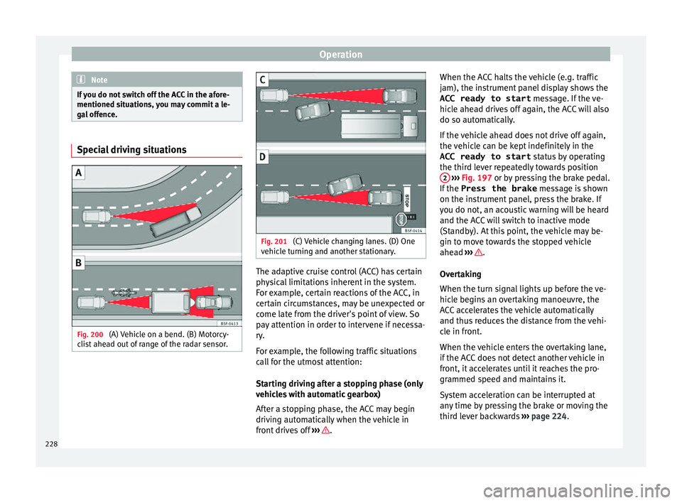
gal offence. Special driving situations
Fig. 200
(A) Vehicle on a bend. (B) Motorcy-
c li
s
t ahead out of range of the radar sensor. Fig. 201
(C) Vehicle changing lanes. (D) One
v ehic
l
e turning and another stationary. The adaptive cruise control (ACC) has certain
ph
y
s
ical limitations inherent in the system.
For example, certain reactions of the ACC, in
certain circumstances, may be unexpected or
come late from the driver's point of view. So
pay attention in order to intervene if necessa-
ry.
For example, the following traffic situations
call for the utmost attention:
Starting driving after a stopping phase (only
vehicles with automatic gearbox)
After a stopping phase, the ACC may begin
driving automatically when the vehicle in
front drives off ››› .When the ACC halts the vehicle (e.g. traffic
j
am), the in
s
trument panel display shows the
ACC ready to start message. If the ve-
hicle ahead drives off again, the ACC will also
do so automatically.
If the vehicle ahead does not drive off again,
the vehicle can be kept indefinitely in the
ACC ready to start status by operating
the third lever repeatedly towards position 2
› ››
Fig. 197
or b
y pressing the brake pedal.
If the Press the brake message is shown
on the instrument panel, press the brake. If
you do not, an acoustic warning will be heard
and the ACC will switch to inactive mode
(Standby). At this point, the vehicle may be-
gin to move towards the stopped vehicle
ahead ››› .
Ov er
t
aking
When the turn signal lights up before the ve-
hicle begins an overtaking manoeuvre, the
ACC accelerates the vehicle automatically
and thus reduces the distance from the vehi-
cle in front.
When the vehicle enters the overtaking lane,
if the ACC does not detect another vehicle in
front, it accelerates until it reaches the pro-
grammed speed and maintains it.
System acceleration can be interrupted at
any time by pressing the brake or moving the
third lever backwards ››› page 224.
228
Page 245 of 348
Driver assistance systems
Engine
D ependin
g on the pr
ofile selected, the en-
gine responds more spontaneously or more
in harmony with the movements of the accel-
erator. Additionally, when the Eco profile is
selected, the Start-Stop function is automati-
cally activated.
In vehicles with automatic transmission, the
gear change points are modified to position
them in lower or higher engine speed ranges.
Additionally, the Eco profile activates the in-
ertia function, enabling consumption to be
further reduced.
In manual gearbox vehicles, the Eco profile
causes the gear change recommendation in-
dications that appear on the dash panel to
vary, facilitating more efficient driving.
Address
The power steering varies its driving modes
and adapts to the profile selected, thus offer-
ing the best behaviour for each situation.
Air conditioning
In vehicles with Climatronic, this can operate
in Eco mode, especially restricting fuel con-
sumption. Adaptive cruise control (ACC)
The accel
eration gradient of the adaptive
cruise control varies according to the active
driving profile ››› page 221.
Electronic stability control (ESC)
In the Offroad and Snow driving profiles,
the electronic stability Control (ESC)
››› page 189 adjusts to adapt to the terrain.
In addition, hill descent control (HDC) is acti-
vated in the Offroad profile ››› page 210.
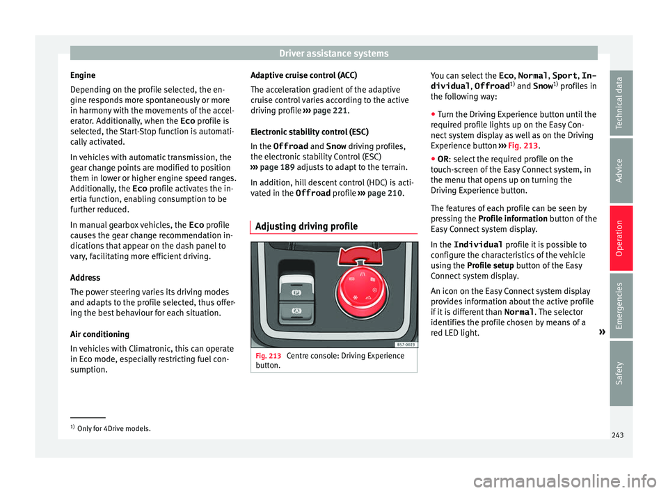
Adjusting driving profile Fig. 213
Centre console: Driving Experience
b utt
on. You can select the
Eco, Normal , Sport, In-
dividual , Offroad1)
and Snow 1)
pr ofi
l
es in
the following way:
● Turn the Driving Experience button until the
required pr
ofile lights up on the Easy Con-
nect system display as well as on the Driving
Experience button ››› Fig. 213.
● OR: select the required profile on the
touc
h-screen of the Easy Connect system, in
the menu that opens up on turning the
Driving Experience button.
The features of each profile can be seen by
pressing the Profile information button of the
Easy Connect system display.
In the Individual profile it is possible to
configure the characteristics of the vehicle
using the Profile setup button of the Easy
Connect system display.
An icon on the Easy Connect system display
provides information about the active profile
if it is different than Normal. The selector
identifies the profile chosen by means of a
red LED light. »1)
Only for 4Drive models.
243
Technical data
Advice
Operation
Emergencies
Safety
Page 266 of 348
Operation
–
or in location s
such as the brow of a hill.
● In order to guarantee good system opera-
tion, keep the ultr
asound sensors clean, free
of snow or ice, and do not cover them with
adhesives or other objects.
● If you use high-pressure or vapour equip-
ment to c
lean the ultrasound sensors, apply
it directly only very briefly and always from a
distance of more than 10 cm.
● Retrofitting of accessories to the vehicle,
such a
s a bicycle rack, may interfere with the
operation of the Parking Aid.
● In order to familiarise yourself with the sys-
tem, it i
s advised that you practice parking in
an area or car park that is free from traffic.
There must be good weather and light condi-
tions.
● The volume and tone of the warnings can
be modified, in addition t
o the indications
››› page 265.
● In vehicles without an inf
otainment system,
these parameters can be modified in a SEAT
Official Service or in a specialised workshop.
● Please observe information on towing a
trail
er ››› page 265.
● The display on the Easy Connect screen
shows
a slight time delay. Parking Aid operation
Manual disconnection of Parking Aid display
(the audibl
e sou
nds remain active)
● Press a button on the main menu of the fac-
tory
-assembled infotainment system.
● OR: press the BA
CK function button.
Park in
g Aid connection
● Engage reverse (for manual gears) or set
the selector l
ever to R (for automatic gears).
Parking Aid disconnection
● Place the selector level in position P, N or D
(for aut om
atic gearboxes) or disengage re-
verse (for manual gearboxes). If you set the
lever to N or D, the system will remain active
for approximately 8 seconds before switching
off, except with Top View Camera*, when it
will be switched off immediately after engag-
ing reverse.
Temporary suppression of sound in Parking
Aid
● Press the function b
utton. If you have the
Top View Camera* system installed, you can-
not use the temporary suppression of sound
in Parking Aid. Switch from reduced to full-screen view if the
rear a
ssist is fitted (Rear View Camera
“RVC”)
● Press the car icon in the reduced view.
If nece
ssary, switch to the rear-assist image
(Rear View Camera “RVC”)
● Engage reverse gear or turn the selector
lever t
o position R.
● OR: press the RVC fu
nction icon.
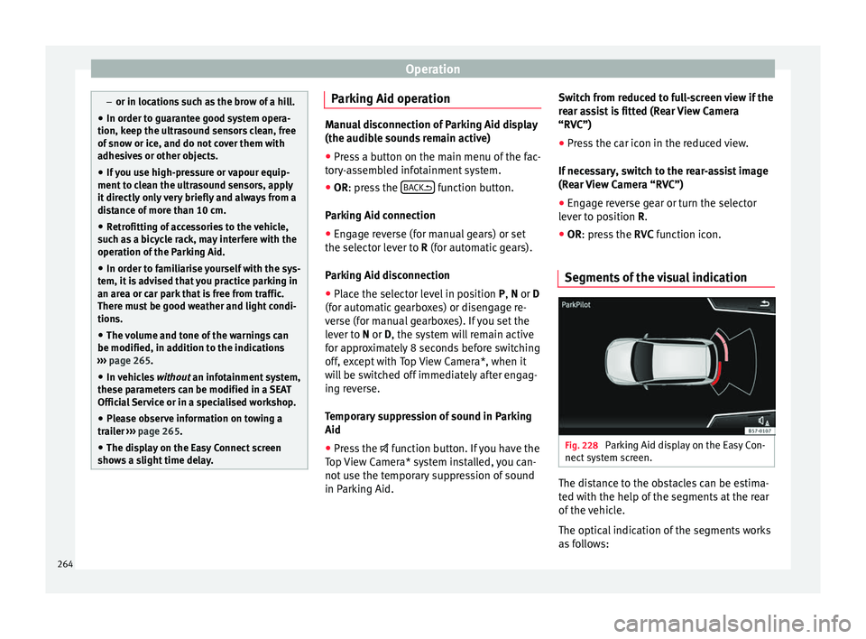
Segments of the visual indication Fig. 228
Parking Aid display on the Easy Con-
nect sy
s
tem screen. The distance to the obstacles can be estima-
t
ed w
ith the help of
the segments at the rear
of the vehicle.
The optical indication of the segments works
as follows:
264
Page 274 of 348
Operation
● If the ar
e
a behind the vehicle is not dis-
played very clearly or is incomplete.
● If the vehicle is heavily loaded at the rear.
● If the position and installation angle of the
camera h
ave been changed, e.g. after a rear-
end collision. Have the system checked by a
specialised workshop.
Familiarising yourself with the system
To familiarise yourself with the system, the
orientation lines and their function, SEAT rec-
ommends practising parking and manoeu-
vring with the rear assist in a place without
too much traffic or in a car park when there
are good weather and visibility conditions.
Cleaning the camera lens
Keep the camera lens clean and clear of snow
and ice:
● Moisten the lens using a normal alcohol-
based gl
ass cleaning product and clean the
lens with a dry cloth.
● Remove snow using a small brush.
● Use de-icing spray to remove any ice. CAUTION
● Never u se abr
asive cleaning products to
clean the camera lens.
● Do not use hot or warm water to remove ice
or snow fr
om the camera lens. Doing so could
damage the camera. Parking and manoeuvring with the
r
e
ar a
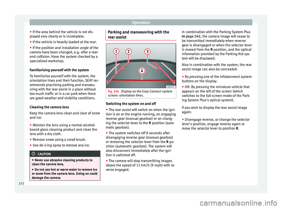
ssist Fig. 234
Display on the Easy Connect system
s c
r
een: orientation lines. Switching the system on and off
●
The rear assist will switch on when the igni-
tion i s
on or the en
gine running, on engaging
reverse gear (manual gearbox) or on chang-
ing the selector lever to the R position (auto-
matic gearbox).
● The system switches off 8 seconds after
diseng
aging reverse gear (manual gearbox)
or removing the selector lever from the R po-
sition (automatic gearbox). The system will
also disconnect immediately after the igni-
tion is switched off.
● The camera will stop transmitting images
above the s
peed of 15 km/h (9 mph) with re-
verse engaged. In combination with the Parking System Plus
›››
page 262, the camera image will cease to
be transmitted immediately when reverse
gear is disengaged or when the selector lever
is moved from the R position, and the optical
information provided by the Parking Aid sys-
tem will be displayed.
Also in combination with the system, the rear
assist image can also be concealed:
● By pressing one of the Infotainment system
button
s on the display.
● OR: By pressing the miniature vehicle that
appear
s on the left of the screen (which
switches to the full-screen mode of the Park-
ing System Plus's optical system).
If you wish to display the rear assist image
again:
● Disengage reverse, or change the selector
lever's
position, engage reverse again or
move the selector lever to position R.
272
Page 275 of 348
Towing bracket device*
● OR: Pr e
s
s the RVC function button 1)
Meaning of the orientation lines
››› Fig. 234
Side lines: extension of the vehicle (the
approximate width of the vehicle plus the
rear view mirrors) on the road surface.
End of the side lines: the area marked in
green ends approximately 2 m behind
the vehicle on the road surface.
Intermediate line: indicates a distance of
approximately 1 m behind the vehicle on
the road surface.
Red horizontal line: indicates a safe dis-
tance of approximately 40 cm at the rear
of the vehicle on the road surface.
Parking manoeuvre ● Place the vehicle in front of the parking
spac
e and engage reverse gear (manual
gearbox) or move the selector to the R posi-
tion (automatic gearbox).
● Reverse slowly, and turn the steering wheel
so that the s
ide orientation lines lead to-
wards the parking space. 1 2
3
4 ●
Guide the v
ehic
le into the parking space so
that the side orientation lines run parallel to
it. Towing bracket device*
T r
ai
ler mode
Introduction Take into account country-specific regula-
tions
about
driving with a trailer and the use
of a towing bracket.
The vehicle has been developed primarily for
carrying people, although it can also be used
to tow a trailer if fitted with the correspond-
ing technical equipment. This additional load
has an effect on the useful life, fuel con-
sumption and vehicle performance and in
some cases can reduce the service intervals.
Driving with a trailer requires more force from
the vehicle, and thus more concentration
from the driver.
In winter, winter tyres should be fitted on
both the vehicle and the trailer.
Maximum vertical load technically permissi-
ble on the coupling
The maximum vertical load technically per-
mitted from the trailer draw bar on the towing
bracket's tow hitch is 80 kg. »1)
WARNING: the RVC function b
utton will only be ac-
tivated and available when the reverse gear is en-
gaged or the selector lever is set to position R.
273
Technical data
Advice
Operation
Emergencies
Safety
Page 282 of 348
Operation
To promote safety while driving, SEAT recom-
mend s
m
aking the most of the maximum ver-
tical load technically permissible on the cou-
pling device ››› page 273. An insufficient ver-
tical load has a negative influence on the be-
haviour of both the vehicle and trailer.
The vertical load increases the weight on the
rear axle, reducing the vehicle's carrying ca-
pacity.
Gross combination weight of the towing ve-
hicle and trailer
The gross combination weight is the actual
weight of the loaded vehicle plus the actual
weight of the loaded trailer.
In some countries trailers are classified into
distinct categories. SEAT recommends ob-
taining information from a specialised work-
shop regarding which type of trailer is most
suitable for your vehicle.
Trailer loading
The weight of the towing vehicle and trailer
must be balanced. In order to do this, the
load must be as close as possible to the max-
imum vertical load technically permissible on
the coupling point, and it must be evenly dis-
tributed between the back and front of the
trailer:
● Distribute loads in the trailer so that heavy
obj
ects are as near to the axle as possible or
above it. ●
Secure the tr
ailer load properly.
Tyre pressure
Set the tyre pressure of the trailer tyres in ac-
cordance with the trailer manufacturer's rec-
ommendations.
When towing a trailer, inflate the tyres of the
towing vehicle with the maximum allowable
pressure ››› page 308. WARNING
If the maximum permissible axle weight, the
max imum lo
ad technically permissible on the
coupling point, the maximum authorised ve-
hicle weight or the gross combination weight
of the towing vehicle and trailer are excee-
ded, accidents and serious injuries may oc-
cur.
● Never exceed the values indicated!
● The actual weight on the front and rear
axle
s must never exceed the maximum per-
missible axle weight. The weight on the front
and rear axles must never exceed the maxi-
mum permissible weight. WARNING
A shift in weight could jeopardize the stabili-
ty and sec urity
of the towing vehicle and
trailer, which could lead to accidents and se-
rious injuries.
● Always load the trailer correctly. ●
Alw a
ys secure the load properly using belts
or straps that are suitable and in good condi-
tion. Driving with a trailer
Adjusting the headlights
When to
w
ing a trailer, the front part of the ve-
hicle could lift up, and if the dipped beams
are on, this could dazzle other drivers. Use
the headlight range control to lower the cone
of light. If you do not have headlight range
control, have the headlights adjusted by a
specialised workshop.
Special characteristics of driving with a trail-
er
● If your trailer has an overru
n brake, brake
gently at first and then rapidly. This will pre-
vent the jerking that can be caused by the
locking of trailer wheels.
● Due to the gross combination weight of the
tow
ing vehicle and trailer, the braking dis-
tance increases.
● When going down a slope, go into a lower
gear (if
using a manual gearbox or the tip-
tronic automatic gearbox mode) to take ad-
vantage of the braking power provided by the
engine. Otherwise, the braking system could
overheat and even fail.
280
Page 283 of 348
Towing bracket device*
● The tr ai
l
er weight, as well as the gross com-
bination weight of the towing vehicle and
trailer, change the centre of gravity and the
properties of the vehicle.
● If the towing vehicle is empty and the trail-
er is lo
aded, then the load distribution is in-
correct. Under these conditions, drive slowly
and with extra caution.
Hill starts with a trailer
Depending on the slope of the hill and the
combination weight of the towing vehicle
and trailer, the vehicle might start rolling
backwards slightly when you first start up.
For hill-starting with a trailer, do the follow-
ing:
● Press and hold the brake pedal.
● Press the button t
o disconnect the elec-
tronic parking brake ››› page 186.
● If the vehicle is equipped with a manual
gearbo
x, push the clutch pedal all the way
down.
● Put the vehicle into first gear or turn the se-
lector l
ever to position D/S ››› page 192.
● Pull out the button and ho
ld it in that
position to stop the towing vehicle and trailer
with the electronic parking brake.
● Release the brake pedal.
● Start driving slowly. To do this, in the case
of a manual
gearbox, slowly release the
clutch pedal. ●
Do not rel
ease the button until the en-
gine has sufficient force to start driving. WARNING
If a trailer is pulled incorrectly, this may lead
to lo s
s of control of the vehicle and serious
injury.
● Driving with a trailer and transporting
heavy or l
arge objects will change the vehicle
handling and braking distances.
● Always drive cautiously and carefully.
Brake e
arlier than usual.
● Adapt your speed and driving style at all
times t
o suit visibility, weather, road and traf-
fic conditions. Slow down, especially when
driving down hills or slopes.
● Accelerate with particular care and caution.
Avoid s
udden braking and manoeuvres.
● Take great care when overtaking. Reduce
speed immediat
ely if you notice that the trail-
er is swaying, however slightly.
● Never attempt to “straighten” the towing
vehicl
e and trailer while accelerating.
● Take into account the speed limit for vehi-
cle
s with a trailer, as it could be lower than
for vehicles without a trailer. Stabilisation of the towing vehicle
and tr
ai
l
er The stabilisation of the towing vehicle and
trai
l
er together is an additional function of
the electronic stability control (ESC).
If the system detects that the trailer is sway-
ing, it intervenes automatically with the driv-
er steering recommendation to reduce the
swaying of the trailer.
Requirements for the stabilisation of the
towing vehicle and trailer
● The vehicle is factory-equipped with a tow-
ing br ac
ket or has been retro-fitted with a
compatible towing bracket.
● The ESC and ASR are active. The control
lamp or is
not lit up on the instrument
panel.
● The trailer is electrically connected to the
tow
ing vehicle through the trailer power
socket.
● The vehicle is travelling at over 60 km/h
(appro
x. 37 mph).
● The maximum vertical load technically per-
miss
ible is being utilised on the coupling de-
vice.
● The trailer has a rigid draw bar.
● If the trailer has brakes, it must be equip-
ped with a mech
anical overrun brake. »
281
Technical data
Advice
Operation
Emergencies
Safety