low beam Seat Ibiza ST 2012 Owner's manual
[x] Cancel search | Manufacturer: SEAT, Model Year: 2012, Model line: Ibiza ST, Model: Seat Ibiza ST 2012Pages: 282, PDF Size: 3.77 MB
Page 68 of 282
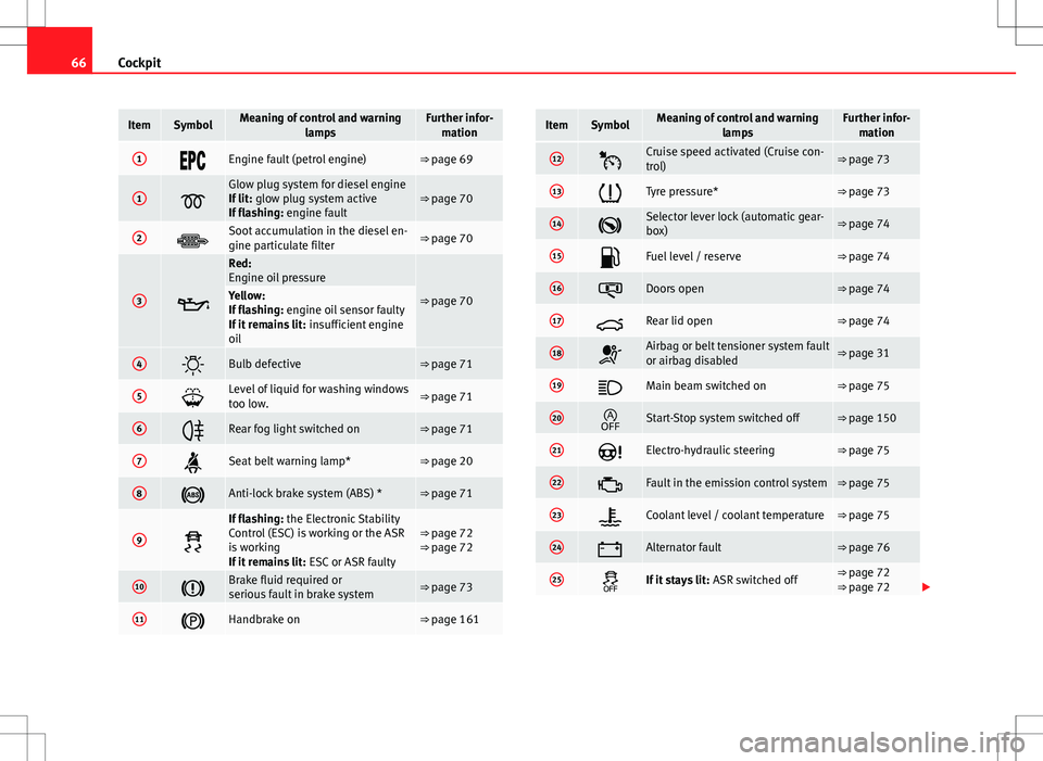
66Cockpit
ItemSymbolMeaning of control and warning
lampsFurther infor-mation
1Engine fault (petrol engine)⇒ page 69
1
Glow plug system for diesel engine
If lit: glow plug system active
If flashing: engine fault⇒ page 70
2Soot accumulation in the diesel en-
gine particulate filter⇒ page 70
3
Red:
Engine oil pressure
⇒ page 70Yellow:
If flashing: engine oil sensor faulty
If it remains lit: insufficient engine
oil
4Bulb defective⇒ page 71
5Level of liquid for washing windows
too low.⇒ page 71
6Rear fog light switched on⇒ page 71
7Seat belt warning lamp*⇒ page 20
8Anti-lock brake system (ABS) *⇒ page 71
9
If flashing: the Electronic Stability
Control (ESC) is working or the ASR
is working
If it remains lit: ESC or ASR faulty⇒ page 72
⇒ page 72
10Brake fluid required or
serious fault in brake system⇒ page 73
11Handbrake on⇒ page 161
ItemSymbolMeaning of control and warning
lampsFurther infor-mation
12Cruise speed activated (Cruise con-
trol)⇒ page 73
13Tyre pressure*⇒ page 73
14Selector lever lock (automatic gear-
box)⇒ page 74
15Fuel level / reserve⇒ page 74
16Doors open⇒ page 74
17Rear lid open⇒ page 74
18Airbag or belt tensioner system fault
or airbag disabled⇒ page 31
19Main beam switched on⇒ page 75
20Start-Stop system switched off⇒ page 150
21Electro-hydraulic steering⇒ page 75
22Fault in the emission control system⇒ page 75
23Coolant level / coolant temperature⇒ page 75
24Alternator fault⇒ page 76
25If it stays lit: ASR switched off⇒ page 72
⇒ page 72
Page 77 of 282
75
Cockpit
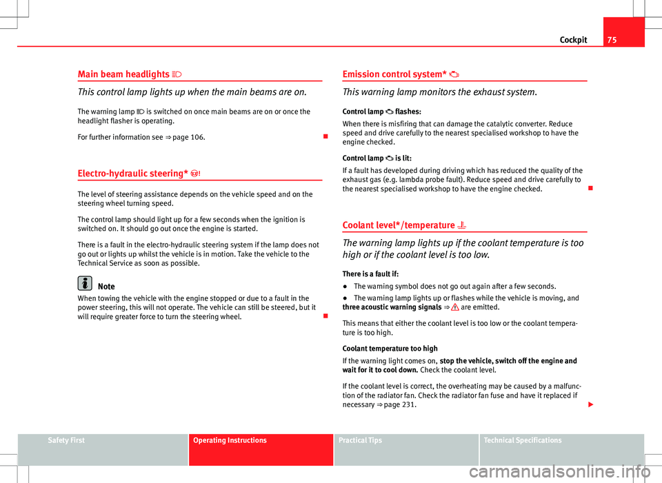
Main beam headlights
This control lamp lights up when the main beams are on.
The warning lamp is switched on once main beams are on or once the
headlight flasher is operating.
For further information see ⇒ page 106.
Electro-hydraulic steering*
The level of steering assistance depends on the vehicle speed and on the
steering wheel turning speed.
The control lamp should light up for a few seconds when the ignition is
switched on. It should go out once the engine is started.
There is a fault in the electro-hydraulic steering system if the lamp does not
go out or lights up whilst the vehicle is in motion. Take the vehicle to the
Technical Service as soon as possible.
Note
When towing the vehicle with the engine stopped or due to a fault in the
power steering, this will not operate. The vehicle can still be steered, but it
will require greater force to turn the steering wheel. Emission control system*
This warning lamp monitors the exhaust system.
Control lamp flashes:
When there is misfiring that can damage the catalytic converter. Reduce
speed and drive carefully to the nearest specialised workshop to have the
engine checked.
Control lamp is lit:
If a fault has developed during driving which has reduced the quality of the
exhaust gas (e.g. lambda probe fault). Reduce speed and drive carefully to
the nearest specialised workshop to have the engine checked.
Coolant level*/temperature
The warning lamp lights up if the coolant temperature is too
high or if the coolant level is too low.
There is a fault if:
● The warning symbol does not go out again after a few seconds.
● The warning lamp lights up or flashes while the vehicle is moving, and
three acoustic warning signals ⇒
are emitted.
This means that either the coolant level is too low or the coolant tempera-
ture is too high.
Coolant temperature too high
If the warning light comes on, stop the vehicle, switch off the engine and
wait for it to cool down. Check the coolant level.
If the coolant level is correct, the overheating may be caused by a malfunc-
tion of the radiator fan. Check the radiator fan fuse and have it replaced if
necessary ⇒ page 231.
Safety FirstOperating InstructionsPractical TipsTechnical Specifications
Page 104 of 282
102Lights and visibility
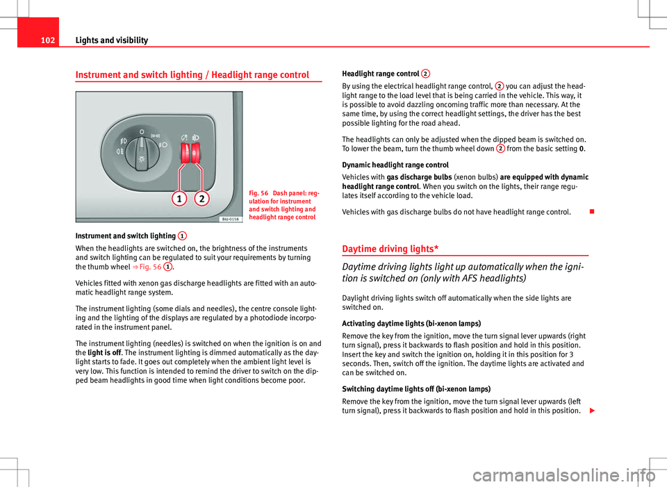
Instrument and switch lighting / Headlight range control
Fig. 56 Dash panel: reg-
ulation for instrument
and switch lighting and
headlight range control
Instrument and switch lighting 1
When the headlights are switched on, the brightness of the instruments
and switch lighting can be regulated to suit your requirements by turning
the thumb wheel
⇒ Fig. 56 1
.
Vehicles fitted with xenon gas discharge headlights are fitted with an auto-
matic headlight range system.
The instrument lighting (some dials and needles), the centre console light-
ing and the lighting of the displays are regulated by a photodiode incorpo-
rated in the instrument panel.
The instrument lighting (needles) is switched on when the ignition is on and
the light is off . The instrument lighting is dimmed automatically as the day-
light starts to fade. It goes out completely when the ambient light level is
very low. This function is intended to remind the driver to switch on the dip-
ped beam headlights in good time when light conditions become poor. Headlight range control
2
By using the electrical headlight range control, 2 you can adjust the head-
light range to the load level that is being carried in the vehicle. This way, it
is possible to avoid dazzling oncoming traffic more than necessary. At the
same time, by using the correct headlight settings, the driver has the best
possible lighting for the road ahead.
The headlights can only be adjusted when the dipped beam is switched on.
To lower the beam, turn the thumb wheel down 2
from the basic setting
0.
Dynamic headlight range control
Vehicles with gas discharge bulbs (xenon bulbs) are equipped with dynamic
headlight range control . When you switch on the lights, their range regu-
lates itself according to the vehicle load.
Vehicles with gas discharge bulbs do not have headlight range control.
Daytime driving lights*
Daytime driving lights light up automatically when the igni-
tion is switched on (only with AFS headlights)
Daylight driving lights switch off automatically when the side lights are
switched on.
Activating daytime lights (bi-xenon lamps)
Remove the key from the ignition, move the turn signal lever upwards (right
turn signal), press it backwards to flash position and hold in this position.
Insert the key and switch the ignition on, holding it in this position for 3
seconds. Then, switch off the ignition. The daytime lights are activated and
can be switched on.
Switching daytime lights off (bi-xenon lamps)
Remove the key from the ignition, move the turn signal lever upwards (left
turn signal), press it backwards to flash position and hold in this position.
Page 108 of 282
106Lights and visibility
Note
● The battery will run down if the hazard warning lights are left on for a
long time, even if the ignition is switched off.
● The use of the hazard warning lights described here is subject to the rel-
evant statutory requirements.
Turn signal and main beam headlight lever
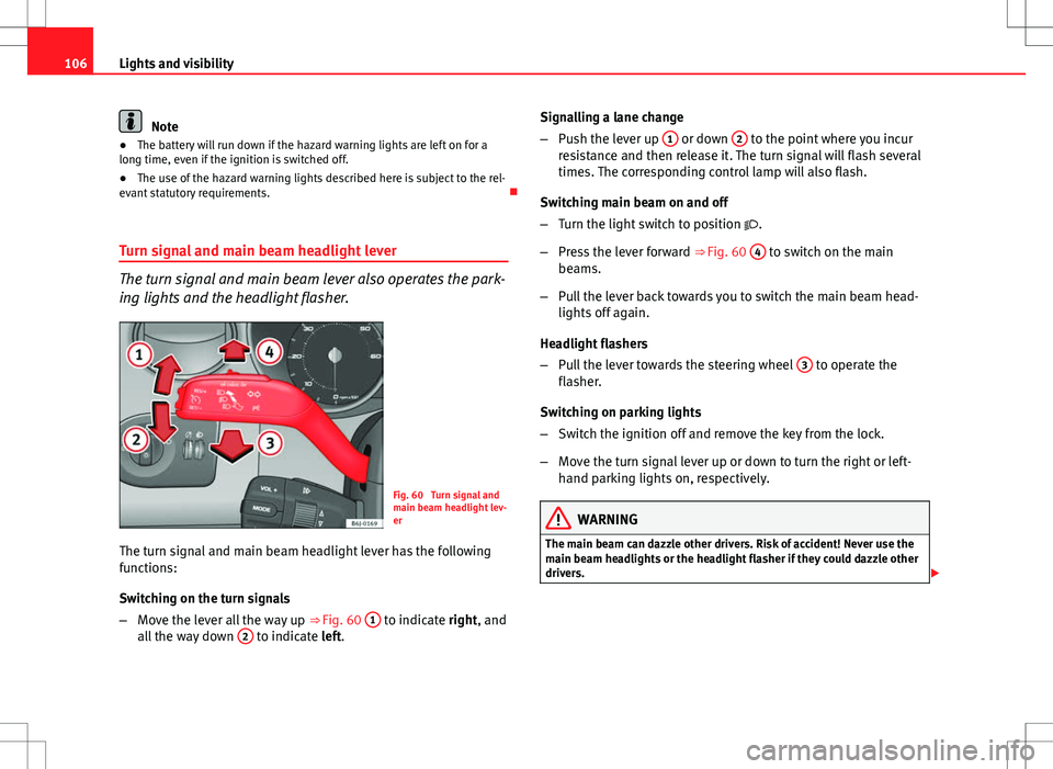
The turn signal and main beam lever also operates the park-
ing lights and the headlight flasher.
Fig. 60 Turn signal and
main beam headlight lev-
er
The turn signal and main beam headlight lever has the following
functions:
Switching on the turn signals
– Move the lever all the way up ⇒
Fig. 60 1
to indicate right, and
all the way down 2 to indicate left. Signalling a lane change
–
Push the lever up 1
or down 2 to the point where you incur
resistance and then release it. The turn signal will flash several
times. The corresponding control lamp will also flash.
Switching main beam on and off
– Turn the light switch to position .
– Press the lever forward ⇒ Fig. 60 4
to switch on the main
beams.
– Pull the lever back towards you to switch the main beam head-
lights off again.
Headlight flashers
– Pull the lever towards the steering wheel 3
to operate the
flasher.
Switching on parking lights
– Switch the ignition off and remove the key from the lock.
– Move the turn signal lever up or down to turn the right or left-
hand parking lights on, respectively.
WARNING
The main beam can dazzle other drivers. Risk of accident! Never use the
main beam headlights or the headlight flasher if they could dazzle other
drivers.
Page 109 of 282
107
Lights and visibility
Note
● The turn signals only work when the ignition is switched on. The corre-
sponding warning lamp or flashes in the instrument panel. The control
lamp flashes when the turn signals are operated, provided a trailer is
correctly attached and connected to the vehicle. If a turn signal bulb is de-
fective, the control lamp flashes at double speed. If the trailer turn signal
bulbs are damaged, control lamp does not light up. Change the bulb.
● The main beam headlights can only be switched on if the dipped beam
headlights are already on. The warning lamp then comes on in the instru-
ment panel.
● The headlight flasher comes on for as long as you pull the lever – even if
no other lights are switched on. The warning lamp then comes on in the
instrument panel.
● When the parking lights are switched on, the headlight and the tail light
on the corresponding side of the vehicle light up. The parking lights will on-
ly work if the key is removed from the ignition. If the lights are switched on,
an audible warning will be emitted while the driver door is open.
● If the turn signal lever is left on after the key has been taken out of the
ignition lock, an acoustic signal sounds when the driver door is opened.
This is a reminder to switch off the turn signal, unless of course you wish to
leave the parking light on. Interior lights
Front interior light
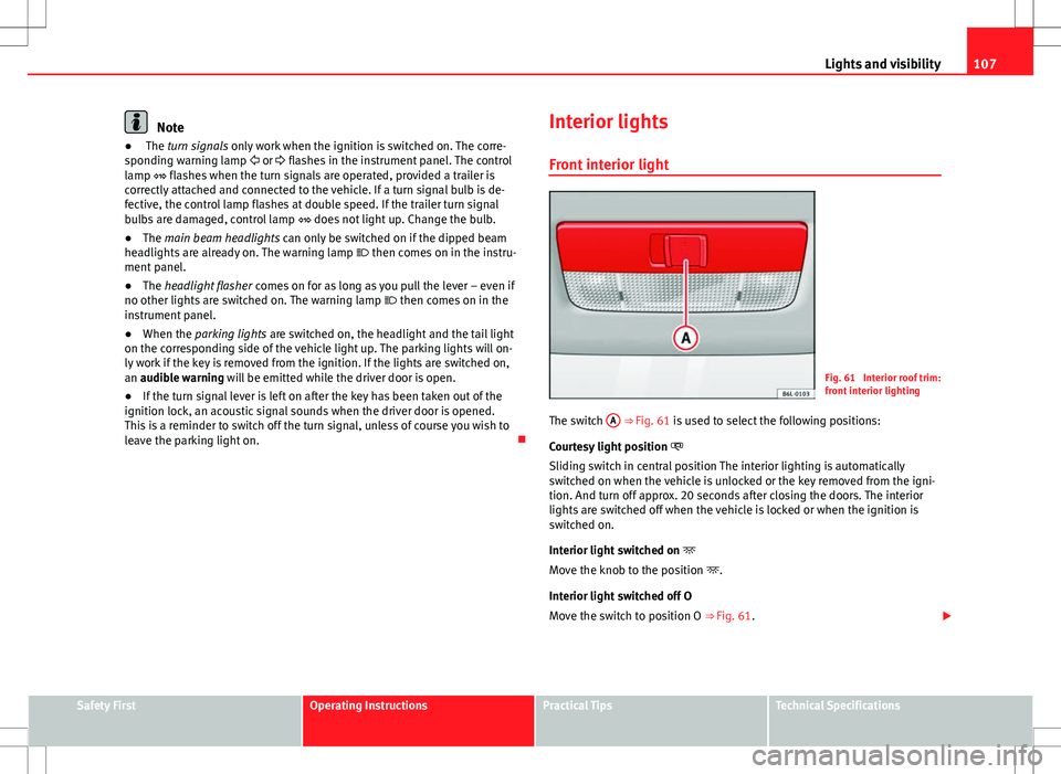
Fig. 61 Interior roof trim:
front interior lighting
The switch A
⇒ Fig. 61 is used to select the following positions:
Courtesy light position
Sliding switch in central position The interior lighting is automatically
switched on when the vehicle is unlocked or the key removed from the igni-
tion. And turn off approx. 20 seconds after closing the doors. The interior
lights are switched off when the vehicle is locked or when the ignition is
switched on.
Interior light switched on
Move the knob to the position .
Interior light switched off O
Move the switch to position O ⇒ Fig. 61.
Safety FirstOperating InstructionsPractical TipsTechnical Specifications
Page 167 of 282
165
Driving
Switching the cruise control system on and off
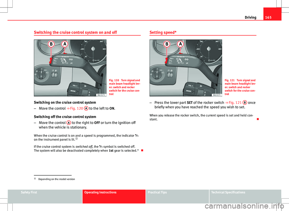
Fig. 120 Turn signal and
main beam headlight lev-
er: switch and rocker
switch for the cruise con-
trol
Switching on the cruise control system
– Move the control ⇒ Fig. 120 A
to the left to
ON.
Switching off the cruise control system
– Move the control A
to the right to
OFF or turn the ignition off
when the vehicle is stationary.
When the cruise control is on and a speed is programmed, the indicator
on the instrument panel is lit. 1)
If the cruise control system is switched off, the symbol is switched off.
The system will also be deactivated completely when 1st gear is selected.*Setting speed*
Fig. 121 Turn signal and
main beam headlight lev-
er: switch and rocker
switch for the cruise con-
trol
– Press the lower part SET of the rocker switch ⇒ Fig. 121 B
once
briefly when you have reached the speed you wish to set.
When you release the rocker switch, the current speed is set and held con-
stant.
1)
Depending on the model version
Safety FirstOperating InstructionsPractical TipsTechnical Specifications
Page 168 of 282
166Driving
Adjusting set speed*
The speed can be altered without touching the accelerator or
the brake.
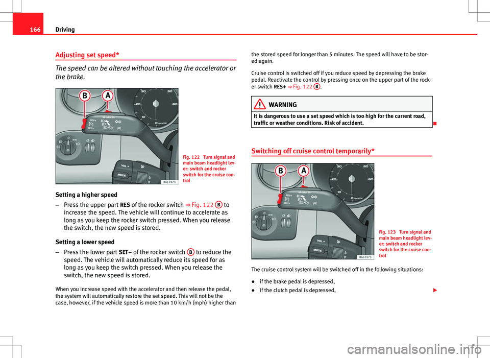
Fig. 122 Turn signal and
main beam headlight lev-
er: switch and rocker
switch for the cruise con-
trol
Setting a higher speed
– Press the upper part RES of the rocker switch ⇒ Fig. 122 B
to
increase the speed. The vehicle will continue to accelerate as
long as you keep the rocker switch pressed. When you release
the switch, the new speed is stored.
Setting a lower speed
– Press the lower part SET– of the rocker switch B
to reduce the
speed. The vehicle will automatically reduce its speed for as
long as you keep the switch pressed. When you release the
switch, the new speed is stored.
When you increase speed with the accelerator and then release the pedal,
the system will automatically restore the set speed. This will not be the
case, however, if the vehicle speed is more than 10 km/h (mph) higher than the stored speed for longer than 5 minutes. The speed will have to be stor-
ed again.
Cruise control is switched off if you reduce speed by depressing the brake
pedal. Reactivate the control by pressing once on the upper part of the rock-
er switch RES+ ⇒ Fig. 122
B
.
WARNING
It is dangerous to use a set speed which is too high for the current road,
traffic or weather conditions. Risk of accident.
Switching off cruise control temporarily*
Fig. 123 Turn signal and
main beam headlight lev-
er: switch and rocker
switch for the cruise con-
trol
The cruise control system will be switched off in the following situations:
● if the brake pedal is depressed,
● if the clutch pedal is depressed,
Page 169 of 282
167
Driving
● if the vehicle is accelerated to over 180 km/h (110 mph),
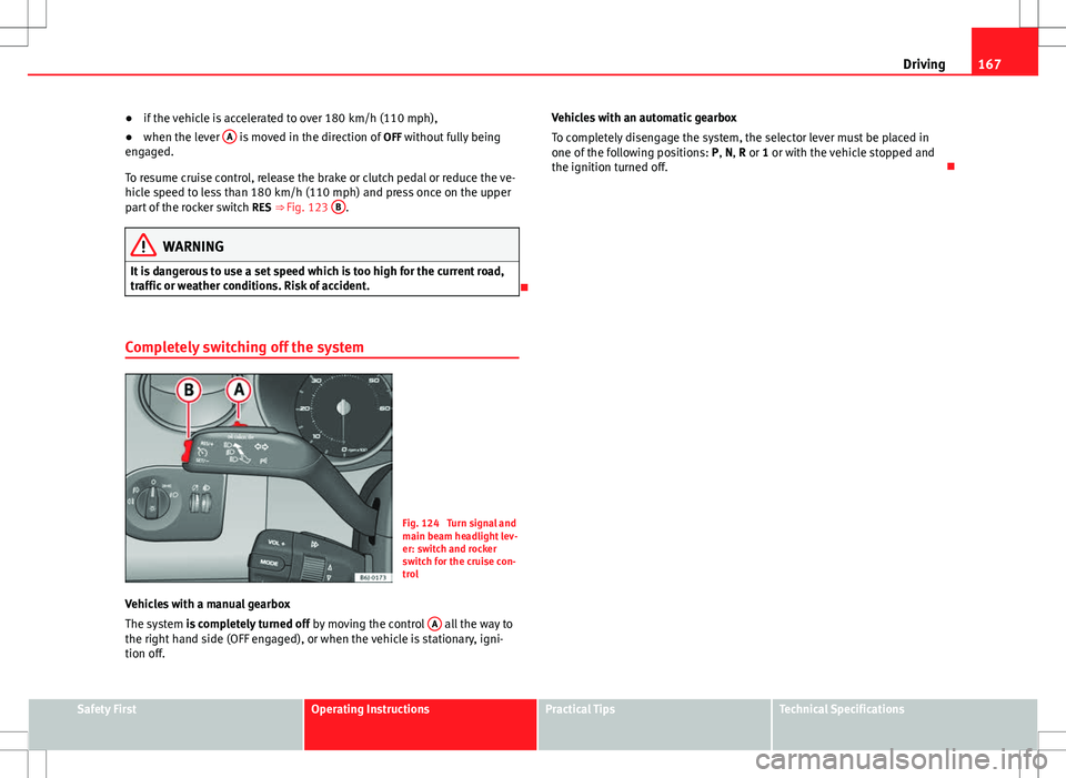
● when the lever A
is moved in the direction of
OFF without fully being
engaged.
To resume cruise control, release the brake or clutch pedal or reduce the ve-
hicle speed to less than 180 km/h (110 mph) and press once on the upper
part of the rocker switch RES ⇒ Fig. 123 B
.
WARNING
It is dangerous to use a set speed which is too high for the current road,
traffic or weather conditions. Risk of accident.
Completely switching off the system
Fig. 124 Turn signal and
main beam headlight lev-
er: switch and rocker
switch for the cruise con-
trol
Vehicles with a manual gearbox
The system is completely turned off by moving the control A
all the way to
the right hand side (OFF engaged), or when the vehicle is stationary, igni-
tion off. Vehicles with an automatic gearbox
To completely disengage the system, the selector lever must be placed in
one of the following positions:
P, N, R or 1 or with the vehicle stopped and
the ignition turned off.
Safety FirstOperating InstructionsPractical TipsTechnical Specifications
Page 180 of 282
178Driving and the environment
●Reduction of volatile compounds in plastics
● CFC-free refrigerant in air conditioner
Compliance with prohibited materials regulation : cadmium, lead, mercury,
chrome VI.
Manufacturing methods
● Use of recycled material for manufacturing plastic parts
● Solvent-free cavity sealing
● Solvent-free wax for protecting the vehicles in transit
● Solvent-free adhesives
● No CFCs used in production
● Surplus materials used extensively for energy conversion and building
materials
● Overall water consumption reduced
● Heat recovery systems
● The use of water-soluble paints
Driving abroad Observations
To drive abroad, the following must be taken into consideration:
● For vehicles fitted with a catalytic converter ensure that unleaded petrol
is available for the journey. See the chapter “Refuelling”. Automobile organ-
isations will have information about service station networks selling unlea-
ded fuel.
● In some countries, it is possible that your vehicle model is not sold, and
therefore spare parts are not available or the Technical Services can only
carry out limited repairs. SEAT importers and distributors will gladly provide information about the
technical preparations that you vehicle requires and also about necessary
maintenance and repair possibilities.
Adhesive strips for headlights
If you have to drive a right-hand drive vehicle in a left-hand drive country, or
vice versa, the asymmetric dipped beam headlights will dazzle oncoming
traffic.
To prevent dazzling, you must apply stickers to certain parts of the head-
light lenses. Further information is available at your Technical Service.
In vehicles with adaptive headlights, the rotation system must previously be
disconnected. To do this, please go to a specialised workshop.
Trailer towing What do you need to bear in mind when towing a trailer?
Your vehicle may be used to tow a trailer when fitted with the correct equip-
ment.
If the vehicle is supplied with a factory-fitted towing bracket it will already
have the necessary technical modifications and meet the statutory require-
ments for towing a trailer. If you wish to retrofit a towing bracket, consult
⇒ page 192.
Connectors
Your vehicle is fitted with a 12-pin connector for the electrical connection
between the trailer and the vehicle.
Page 234 of 282
232If and when
Fuses on left side of dash panel
Fuses
NumberConsumerAmps1Power steering/Engine operation/Flow meter7,5
2
Diagnostics/Heater/Autoclimate/Climatronic/
Electric anti-dazzle mirror/Navigator/Air condi-
tioning pressure switch/ Climate fan/AFS Control
unit/Coming home relay/Soundaktor/CCS
10
3Petrol engine control unit/Diesel engine control
unit/Relay coils/Engine operation/Bi-turbo fuel
control unit5
4ABS-ESC Control unit/RKA Switch/Gateway con-
trol unit/ESC Relay/Rotation sensor10
5Reverse light/Heating nozzles106Instrument panel57Retro fog light/Start-Stop relays7,5
8Paddle levers on steering wheel for automatic
gearbox2
9Headlight lever/Windscreen wiper switch1010BCM Electronic control unit power supply511Airbag control unit512Automatic gearbox/ LPG system1013Exterior mirror control514Left-hand AFS headlights1515Right-hand AFS headlights1516Vacant 17Number plate light518Clean pump7,519Electronic control unit520Turn signals/Brake lights15
NumberConsumerAmps21Lights control, instrument panel522Heated mirrors5
23Engine injection module/Rain sensor/Automatic
gearbox lever/Main petrol relay7,5
24Luggage compartment light, interior light, glove
compartment light, side lights10
25Parking aid526Towing hook 27Headlight control528Lambda probe10
29Vacuum pump/LPG power supply/High-pressure
pump15, 20, 20a)
30Engine solenoid coils/Additional heating relay/
Pressure sensor/AKF Valve10A
31Petrol engine operation/Glow plugs/Relay coil/
Electric fan/Secondary water pump relay/Flow-
meter10
32Engine control unit15, 20,
30 b)
33Clutch switch sensor/Additional heating relay
coil/ Servo sensor5
34Fuel control unit / Vacuum pump1535Vacant 36Main beam with/without AFS10, 15 c)
37Kombi/Coming Home relay/Main beam head-
lights relay10
38Engine heater3039Vacant 4012 Volt Input/Cigarette lighter1541Heated seats control unit / Cup Holder25