service interval Seat Toledo 2016 Owner's manual
[x] Cancel search | Manufacturer: SEAT, Model Year: 2016, Model line: Toledo, Model: Seat Toledo 2016Pages: 248, PDF Size: 5.82 MB
Page 32 of 248
The essentials
the driver message Speed limit excee-
ded! wi
l
l be displayed simultaneously on the
instrument panel. The warning lamp
switches off when reducing speed below the
stored maximum limit.
Speed warning programming is recommen-
ded if you wish to be reminded of a maxi-
mum speed, such as when travelling in a
country with different speed limits or for a
maximum speed for winter tyres.
Setting speed limit warning
You can use the radio or the Easy Connect* to
set, alter or cancel the speed limit warning.
● Vehicles with radio : pres
s the button SETUP> control button Driver Assistant
>
Speed warning .
● Vehicles with Easy Connect : pre
s
s the but-
ton Systems or else Vehicle systems >
Driver assistant > Speed warning.
The warning limit can be set from 30 to
240 km/h (20 to 149 mph). The adjustment
is made at 10 km/h (5 mph) intervals. Note
● Ple a
se bear in mind that, even with the
speed warning function, it is still important
to keep an eye on the vehicle speed with the
speedometer and to observe the legal speed
limits. ●
The speed limit w
arning function in the ver-
sion for some countries warns you at a speed
of 120 km/h (75 mph). This is a factory-set
speed limit. Service intervals
The service interval indication appears on the
ins
trument
panel display ›››
Fig. 110
3 .
SEA T di
stinguishes between services with en-
gine oil change (e.g. Oil change service) and
services without engine oil change (e.g. In-
spection).
In vehicles with Services established by time
or mileage, the service intervals are already
pre-defined.
In vehicles with LongLife Service , the inter-
vals are determined individually. Thanks to
technological progress, maintenance work
has been greatly reduced. Because of the
technology used by SEAT, with this service
you only need to change the oil when the ve-
hicle so requires. To calculate this change
(max. 2 years), the vehicle's conditions of
use and individual driving styles are consid-
ered. The advance warning first appears 20
days before the date established for the cor-
responding service. The kilometres (miles)
remaining until the next service are always
rounded up to the nearest 100 km (miles)
and the time is given in complete days. The
current service message cannot be viewed until 500 km after the last service. Prior to
this, on
ly
lines are visible on the display.
Inspection reminder
When the Service date is approaching, when
the ignition is switched on a Service remind-
er is displayed.
Vehicles without text messages : a span-
ner will be displayed on the instrument
panel plus an indication in km.
The kilometres indicated are the maximum
number of kilometres that can be travelled
until the next service. After a few seconds,
the display mode changes. A clock symbol
appears and the number of days until the
next service is due.
Vehicles with text messages : Service in
--- km or --- days will be shown on the
instrument panel display.
Service due
When the service date is due , an audible
warning is given when the ignition is switch-
ed on and the spanner displayed on the
screen flashes for a few seconds .
Vehicles with text messages : Service now
will be shown on the instrument panel dis-
play. 30
Page 33 of 248
The essentials
Reading a service notification
W ith the ignition sw
it
ched on, the engine off
and the vehicle at a standstill, the current
service notification can be read:
Press and hold the button 4 for more than 5
sec ond
s
to consult the service message.
When the service date has passed , a minus
sign is displayed in front of the number of kil-
ometres or days.
Vehicles with text messages : Service
since --- km or --- days ago will be
shown on the display.
The time can also be set via the key and
Set up function button in the Easy Connect
sy s
t
em ›››
page 99.
Resetting service interval display
If the service was not carried out by a SEAT
dealership, the display can be reset as fol-
lows:
● Switch off the ignition, press and hold but-
ton ››
› Fig. 110
4 .
● Switch ignition back on.
● Release the 4
› ›
›
Fig. 110
button and
press it again for the next 20 seconds. Note
● The serv ic
e message disappears after a few
seconds, when the engine is started or when OK/RESET
is pressed on the windscreen wiper
lev er
, or OK on the multifunction steering
wheel.
● In v
ehicles with the LongLife system in
which the batt
ery has been disconnected for
a long period of time, it is not possible to cal-
culate the date of the next service. Therefore
the service interval display may not be cor-
rect. In this case, bear in mind the maximum
service intervals permitted in the ››› Book-
let Maintenance Programme. Cruise control
Oper atin
g the c
ruise control system
(CCS)* Fig. 39
On the left of the steering column:
sw it
c
hes and controls for operating the CCS ●
Sw it
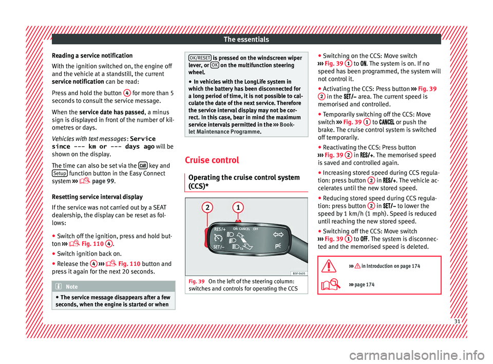
c
hing on the CCS: Move switch
››› Fig. 39 1 to .
The system is on. If no
s peed h
as been programmed, the system will
not control it.
● Activating the CCS: Press button ›››
Fig. 39
2 in the ar
e
a. The current speed is
memorised and controlled.
● Temporarily switching off the CCS: Move
switc
h ››› Fig. 39 1 to
or push the
br ak
e. The cruise control system is switched
off temporarily.
● Reactivating the CCS: Press button
›››
Fig. 39 2 in
. The memorised speed
i
s saved and controlled again.
● Increasing stored speed during CCS regula-
tion: pres
s button 2 in
. The vehicle ac-
c
elerates until the new stored speed.
● Reducing stored speed during CCS regula-
tion: pres
s button 2 in t
o lower the
s peed b
y 1 km/h (1 mph). Speed is reduced
until reaching the new stored speed.
● Switching off the CCS: Move switch
›››
Fig. 39 1 to .
The system is disconnec-
t ed and the memori
sed speed is deleted.
››› in Introduction on page 174
››› page 174 31
Page 36 of 248
The essentials
Fault in the battery.›››
page
212
Driving light totally or partially
faulty.›››
page
83
Fault in the cornering light sys-
tem.››› page
116
Diesel particulate filter blocked›››
page
164
Level of windscreen washer fluid
too low.›››
page
210
Flashing: Fault in the oil level de-
tection. Control manually.›››
page
205
Ignition: Insufficient engine oil.
Fault in the gearbox.›››
page
160
Immobiliser active.›››
page
150
Service interval display›››
page
30
Mobile telephone is connected
via Bluetooth to the original tele-
phone device.›››
Book-
let Radio
or
››› Book-
let Navi-
gation
system
Mobile telephone battery charge
meter. Available only for devices
pre-installed in factory.
Freezing warning. The outside
temperature is lower than +4°C
(+39°F).›››
page
24
Start-Stop system activated.›››
page
181
Start-Stop system unavailable.
Low consumption driving status›››
page
24 On the instrument panel
Front passenger front airbag is
disabled (
).
››› page
66
››› in Warning and control lamps on
page 98
››› page 98 Gearbox lever
M anua
l
gearbox Fig. 42
Gear shift pattern of a 5 or 6-speed
m anual
g
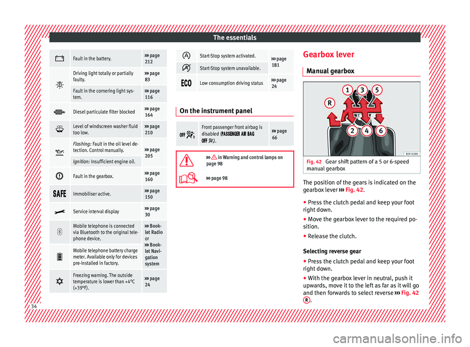
earbox The position of the gears is indicated on the
g
e
arbo
x lever ››› Fig. 42.
● Press the clutch pedal and keep your foot
right down.
● Mo
ve the gearbox lever to the required po-
sition.
● Rel
ease the clutch.
Selecting r
everse gear
● Press the clutch pedal and keep your foot
right down.
● W
ith the gearbox lever in neutral, push it
upwar
ds, move it to the left as far as it will go
and then forwards to select reverse ››› Fig. 42
R .
34
Page 42 of 248
The essentials
Oil Fig. 49
Engine oil dipstick. Fig. 50
In the engine compartment: Engine
oi l
fi
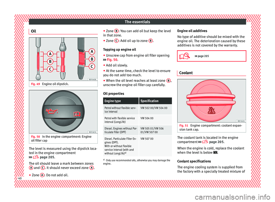
ller cap The level is measured using the dipstick loca-
t
ed in the en
gine c
ompartment
››› page 205.
The oil should leave a mark between zones A and
C . It should never exceed zone
A .
● Zone A : Do not add oil. ●
Zone B : You can add oil but keep the level
in th at
zone.
● Zone C : Add oil up to zone
B .
T op
pin
g up engine oil
● Unscrew cap from engine oil filler opening
›››
Fig. 50.
● Add oil slowly.
● At the same time, check the level to ensure
you do not a
dd too much.
● When the oil level reaches at least zone B ,
u n
s
crew the engine oil filler cap carefully.
Oil properties
Engine typeSpecification
Petrol without flexible serv-
ice intervalVW 502 00/VW 504 00
Petrol with flexible service
interval (LongLife)VW 504 00
Diesel. Engines without Par-
ticulate filter (DPF)VW 505 01/VW 506
01/VW 507 00
Diesel. Particulate Filter En-
gines (DPF).
With or without flexible
service interval (with and
without LongLife) a)VW 507 00
a)
Only use recommended oils, otherwise you may damage the
engine.
Engine oil additives
No type of additive should be mixed with the
engine oil. The deterioration caused by these
additives is not covered by the warranty.
››› page 205 Coolant
Fig. 51
Engine compartment: coolant expan-
s ion t
ank
cap. The coolant tank is located in the engine
c
omp
ar
tment ›››
page 205.
When the engine is cold, replace the coolant
when the level is below .
Coolant specifications
The engine cooling system is supplied from
the factory with a specially treated mixture of 40
Page 86 of 248

Emergencies
Full-LED headlight system*
F u
l
l-LED headlights handle all light functions
(daylight, side light, turn signal, dipped
beam and route light) with light emitting di-
odes (LEDs) as a light source.
Full-LED headlights are designed to last the
lifetime of the car and light bulbs cannot be
replaced. In case of headlight failure, go to
an authorised workshop to have it replaced.
Double headlight bulb change
Changing bulbs requires a certain degree of
practical skill. If in doubt, we recommend you
have defective bulbs changed by a special-
ised service or, in case of an emergency,
seek professional assistance.
● Switch off the ignition and all of the lights
before c
hanging a bulb.
● Do not touch the glass part of the bulb with
your bar
e hands. The fingerprints left on the
glass will vaporise as a result of the heat gen-
erated by the bulb, reducing bulb life and
causing condensation on the reflector sur-
face, thus reducing effectiveness.
● A bulb must only be replaced by one of the
same type. The type i
s indicated on the bulb,
either on the glass part or on the base.
● There is a storage area for the bulb box in
the spar
e wheel well or below the carpet in
the luggage compartment. WARNING
● Tak e p
articular care when working on com-
ponents in the engine compartment if the en-
gine is warm. Risk of burns.
● Bulbs are highly sensitive to pressure. The
glas
s can break when you touch the bulb,
causing injury.
● When changing bulbs, please take care not
to injure
yourself on sharp parts in the head-
light housing. CAUTION
● Remo v
e the ignition key before working on
the electric system. Otherwise, a short circuit
could occur.
● Switch off the lights and the parking light
before c
hanging a bulb. For the sake of the environment
Please ask your specialist retailer how to dis-
pose of u
sed bulbs in the proper manner. Note
● Dependin g on w
eather conditions (cold or
wet), the front lights, the fog lights, the rear
lights and the turn signals may be temporari-
ly misted. This has no influence on the useful
life of the lighting system. By switching on
the lights, the area through which the beam
of light is projected will quickly be demisted.
However, the edges may continue to be mis-
ted. ●
Ple a
se check at regular intervals that all
lighting (especially the exterior lighting) on
your vehicle is functioning properly. This is
not only in the interest of your own safety,
but also that of all other road users.
● Before changing a bulb, make sure you
have the c
orrect new bulb.
● Do not touch the glass part of the bulb with
your bar
e hands, use a cloth or paper towel
instead. Otherwise, the fingerprints left on
the glass will vaporise as a result of the heat
generated by the bulb, they will be deposited
on the reflector and damage its surface. Double headlight bulbs
Fig. 88
Main headlight bulbs. Installation position of double headlight
b
u
l
bs
Side lights
Main beam headlights
A B
84
Page 97 of 248

Instruments and warning lamps
CAUTION
● To pr ev
ent damage to the engine, the rev
counter needle should only remain in the red
zone for a short period of time.
● When the engine is cold, avoid high revs
and heavy ac
celeration and do not make the
engine work hard. For the sake of the environment
Changing up a gear in time reduces fuel con-
sumption and noi se.Rev counter
The rev counter indicates the number of en-
gine r
ev
o
lutions per minute ›››
Fig. 110 1 .
T og
ether w
ith the gear-change indicator, the
rev counter offers you the possibility of using
the engine of your vehicle at a suitable
speed.
The start of the red zone on the dial indicates
the maximum engine speed which may be
used briefly when the engine is warm and af-
ter it has been run in properly. Before reach-
ing this range, you should change to a higher
gear for vehicles with a manual gearbox or for
automatic gearboxes put the selector lever in
“D” or take your foot off the accelerator ped-
al. We recommend that you avoid high revs and
that
you follow the recommendations on the
gear-change indicator. Consult the additional
information in ›››
page 25. CAUTION
Never allow the rev counter needle 1 ›››
Fig. 110 to g o int
o the red zone on the
scale for more than a very brief period, other-
wise there is a risk of engine damage. For the sake of the environment
Changing up a gear early will help you to save
fuel and minimi
se emissions and engine
noise. Indications on the display
A variety of information can be viewed on the
in
s
trument
panel display ›››
Fig. 110 3 de-
pendin g on the
v
ehicle equipment:
● Bonnet, rear lid and doors open
›››
page 25.
● Information and warning texts.
● Mileage.
● Time.
● Navigation instructions.
● Outside temperature.
● Compass. ●
Shift l
ever position ››› page 158.
● Recommended gear (manual gearbox)
›››
page 25.
● Multifunction display (MFD) and menus
with differ
ent setting options ›››
page 23.
● Service interval display ›››
page 30.
● Second speed display ›››
page 26.
● Speed warning function ›››
page 29.
● Start-Stop system status display
›››
page 181.
● Low consumption driving status (ECO)
›››
page 96
● Identifying letters on engine (MKB).
Dist
ance travelled
The odometer registers the total distance
travelled by the car.
The odometer (trip ) shows the distance
travelled since the last odometer reset. The
last digit of the trip recorder indicates distan-
ces of 100 metres or one tenths of a mile.
● Briefly press the button ›››
Fig. 110 4 to re-
set the trip r
ec
order to 0.
● Keep the button 4 pressed for about 3
sec ond
s
and the previous value will be dis-
played. »
95
Technical data
Advice
Operation
Emergencies
Safety
Page 127 of 248

Lights and visibility
●
For s af
ety reasons, the wiper blades should
be changed once or twice a year. They can be
purchased at a SEAT Authorised Service.
● The ignition cannot be switched on while
the winds
creen wiper arms are in a raised po-
sition. Otherwise, the windscreen wipers
would return to their original position and
could damage the paintwork on the bonnet. Note
Keep the wipers clean. The wipers can be
soi led w
ith remains of wax solutions from car
washes ››› page 194.
● On vehicles equipped with windscreen
washer j
ets, these are heated once the en-
gine is running. Operating windscreen wipers and
w
a
sher
s Fig. 140
Window wiper lever. Short wipe
– Give the windscreen a brief w ipe by
moving
the lever down to position 4
› ››
Fig. 140
.
W
ipe intervals/automatic wipe in case of rain
rain sensor*
– Push the lever up to position 1 ›››
Fig. 140.
– With switch A , adjust the wipe interval or
r ain sen
sor sen
sitivity.
Switch A has 4 positions.
The r ain sen
sor* i
s part of the intermittent
wipe function.
The rain sensor* controls the frequency of
the windscreen wiper intervals, depending
on the amount of rain.
Slow wipe
– Push the lever up to position 2 ›››
Fig. 140.
Continuou s
wipe
– Push the lever up to position 3 ›››
Fig. 140.
Autom atic
windscreen wash and wipe
– Pull the lever towards the steering wheel,
pos ition 5
› ›
› Fig. 140
, and the windscreen
washer and wipers are switched on. –
Rele
ase the lever. The washer will stop and
the windscreen wipers will keep running for
1-3 wipes (depending on the windscreen
washer operating time).
Rear window wiper*
– Press the lever forward to position 6 ›››
Fig. 140 and the r e
ar w
indow wiper will
run every 6 seconds.
Automatic rear window wash and wipe* – Press the lever fully forward to position 7 ›››
Fig. 140 and the re ar w
indow wiper and
washer switch on at the same time.
– Release the lever. The rear window washer
wi l
l stop and the rear window wipers will
keep running for 1-3 wipes (depending on
the jet operating time). When released, the
lever remains in position 6 .
Sw it
c
hing off the wipers
– Move the lever to position 0
› ›
› Fig. 140
. WARNING
The rain sensor may not detect enough rain
to sw it
ch on the wipers.
● If necessary, switch on the wipers manually
when water on the w
indscreen obstructs visi-
bility. » 125
Technical data
Advice
Operation
Emergencies
Safety
Page 128 of 248

Operation
Note
Do not put stickers on the windscreen in front
of the r
ain sensor*. This may cause sensor
disruption or faults. Headlight washers*
The headlight washers operate briefly if the
dipped he
a
dlights or headlights are on and
the lever is moved to position 5
››› Fig. 140 .
The he
adlight washer system also operates
every 10 windscreen wash cycles.
Clean off stubborn dirt (insects, etc.) from the
headlights at regular intervals, for instance
when filling the fuel tank. Please observe the
following indications ›››
page 196, Head-
lights.
To ensure the system works properly in win-
ter, keep the nozzle holders free of snow and
remove any ice with a de-icer spray. CAUTION
Never pull on the nozzle holders. Risk of
dam ag
e to the system! Mirrors
R e
ar
view mirror with manual anti-
dazzle device Basic settings
– Push the lever at the bottom of the mirror
for w
ard.
Rear vision mirror anti-dazzle setting – Pull the lever at the bottom of the mirror to-
ward
s you.
Exterior mirrors Read the additional information carefully
› ›
›
page 13
Before beginning any journey, adjust the rear
view mirrors for a good rear visibility. WARNING
● Con v
ex (wide-angle) rear vision mirrors give
a larger field of vision. However, they make
objects appear smaller and further away than
they really are. For this reason, you should
not rely on these rear vision mirrors for judg-
ing the distance of vehicle behind.
● If possible, use the interior rear vision mir-
ror to e
stimate distances to vehicles behind
you. Note
● Exterior mirr or
s are only heated when the
engine is running.
● Do not touch the exterior mirrors when the
heating sy
stem is running.
● If the electrical adjustment should ever fail
to operat
e, the rear vision mirrors can be ad-
justed by hand by pressing the edge of the
mirror glass.
● Visit the technical service in the event of a
fault
in the electrical rear vision mirror ad-
justment system. 126
Page 198 of 248
Advice
Damage to the paint Minor damage to the paint, such as scratches
or st
one c
hips, should be touched up without
delay using paint.
Suitable touch-up brushes or sprays for the
colour of your vehicle can be purchased from
authorised SEAT dealers. Note
We recommend you leave paint damage re-
pair s
to a SEAT Authorised Service. Plastic parts
Exterior plastic parts will come clean using a
d
amp c
loth. If
this is not sufficient, plastic
parts can also be treated with special sol-
vent-free plastic cleaning detergents .
Do not use paint cleaners, polishes or wax on
plastic parts.
Windows and mirrors Remove snow and ice from windows and rear
v
i
s
ion mirrors with a plastic scraper only. To
avoid damaging the surface of the glass, the
scraper should only be pushed in one direc-
tion and not moved to and fro. The windows should also be cleaned on the
inside at
regular intervals.
Use a separate cloth or chamois to dry the
windows and rear vision mirrors.
Do not use the chamois used to polish the
bodywork to dry the windows. Waxing and
polishing residues could cause smears on
the glass and hinder visibility. CAUTION
● Never u se hot
or boiling water to remove
snow and ice from the windows. Risk of crack-
ing glass!
● Make sure you do not damage the paint-
work on the
vehicle on removing snow and
ice from the windows and rear vision mirrors.
● Do not remove the snow or ice dirty with
thick p
articles, e.g. gravel, sand or road salt,
from windows and mirrors. Risk of damage to
the glass and mirror surfaces. Headlights
Use soap and clean, hot water to clean the
fr
ont
he
adlights. CAUTION
● Never rub the he a
dlights to dry them and
do not use sharp objects to clean the plastic
glass material. These could damage the pro- tective paint and cause the headlights to
cr
ac
k.
● Do not use aggressive cleaning products or
chemica
l solvents to clean the glass. This
could damage the headlights. Caring for rubber seals
The weatherstrips on doors and windows will
rem
ain p
liable and last longer if they are oc-
casionally treated with a suitable rubber care
product. This will prevent premature ageing
and leaks. If they are properly cared for, the
seals will be less likely to freeze up in the
winter.
Door lock cylinder Special products must be used to defrost
loc
k
cylinder
s. Note
● Mak e s
ure, when washing the vehicle, that
the least amount of water possible enters the
lock cylinders.
● We recommend the use of products from
the selection of
SEAT Original Accessories to
care for the door lock cylinder. 196
Page 199 of 248

Care and maintenance
Wheels Wheel trims
If
y
ou wash the vehicle regularly, you should
also thoroughly wash the wheel trim. Regu-
larly remove any brake dust and road salt
from the wheels, otherwise the wheel materi-
al could be damaged. Repair any damage to
the wheel paintwork immediately.
Alloy wheels
After thorough washing, treat the wheels
with a protective product for alloy wheels. Do
not use abrasive products to care for the
wheels. WARNING
Moisture, ice and road salt may affect braking
efficiency . Ri
sk of accident! CAUTION
Heavy dirt on the wheels could lead to their
mis a
lignment. This could result in vibrations
being transmitted to the steering wheel that
under certain conditions may cause prema-
ture steering wear. This dirt must be re-
moved. Note
We recommend you leave paint damage re-
pair s
to a SEAT Authorised Service. Vehicle underbody protection
The underside of the vehicle is coated to per-
manently
pr
otect it from chemical and me-
chanical agents.
Given that damage to the protective coating
during driving cannot be completely ruled
out, we recommend you check the condition
of the protective coating on the underbody
and suspension at regular intervals, prefera-
bly before the start and end of the coldest
season of the year.
Authorised SEAT dealers have suitable spe-
cial products and the necessary facilities and
are aware of the techniques required for their
application. We therefore recommend all
touch-up work or additional anti-corrosion
measures be performed by an authorised
SEAT dealer. WARNING
Do not apply underseal or anti-corrosion
co atin
gs to the exhaust pipes, catalytic con-
verter, particulate filter or heat shields on the
exhaust system. Once the engine has
reached operating temperature, these sub-
stances could catch fire. Risk of fire! Cavity waxing
All cavities on the vehicle exposed to corro-
sion ar
e perm
anently factory-protected by a
wax solution .
This wax solution does not need to be
checked or touched up. Should wax run out
of the cavities at high ambient temperatures,
remove it using a plastic scraper and clean
away any stains using lighter fluid. WARNING
Note the regulations concerning safety and
env ir
onmental protection if you use lighter
fluid to remove the wax. Risk of fire! Leatherette and upholstery
Leatherette can be cleaned with a damp
c
loth. If
thi
s is not sufficient, these parts
should only be cleaned with solvent-free
plastic care and cleaning products .
Textile covers and trim parts on doors, boot
lid, etc. can be cleaned with special deter-
gents, e.g. dry foam. A soft sponge or brush
or a micro-fibre cloth for normal cleaning can
be used. Use special products to clean the
headliner. »
197
Technical data
Advice
Operation
Emergencies
Safety