stop start SKODA CITIGO 2013 1.G Owner's Guide
[x] Cancel search | Manufacturer: SKODA, Model Year: 2013, Model line: CITIGO, Model: SKODA CITIGO 2013 1.GPages: 176, PDF Size: 10.54 MB
Page 81 of 176
NoteYou can find more detailed information about the trade-in and recycling of old
cars from a specialist garage.
Avoiding damage to your vehicle
Introduction
This chapter contains information on the following subjects:
General information
78
Driving through water on streets
78
General information
First read and observe the introductory information given on page 78.
Pay attention to low-slung parts of the vehicle, such as the spoiler and exhaust,particularly in the following situations.
› When driving on poorly maintained roads and paths.
› When driving over kerbs.
› When driving on steep ramps, etc.
Particular attention is required for vehicles with sport suspension and when the vehicle is fully laden.
Driving through water on streets
Fig. 76
Driving through waterFirst read and observe the introductory information given on page 78.
The following instructions must be observed if vehicle damage is to be avoided
when driving through water (e.g. flooded roads).
›
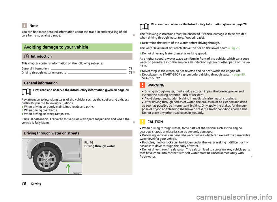
Determine the depth of the water before driving through.
The water level must not reach above the bar on the lower beam » Fig. 76.
›
Do not drive any faster than at a walking speed.
At a higher speed, a water wave can form in front of the vehicle, which can cause
water to penetrate into the engine's air induction system or other parts of the ve-
hicle.
›
Never stop in the water, do not reverse and do not switch the engine off.
›
Deactivate the START-STOP system before driving through water » page 85,
START-STOP .
WARNING■
Driving through water, mud, sludge etc. can impair the braking power and
extend the braking distance – risk of accident!■
Avoid abrupt and sudden braking immediately after water crossings.
■
After driving through bodies of water, the brakes must be cleaned and dried
as soon as possible by intermittent braking. Only apply the brakes for the pur-
pose of drying and cleaning the brake discs if the traffic conditions permit this.
Do not place any other road users in jeopardy.
CAUTION
■ When driving through water, some parts of the vehicle such as the engine,
gearbox, chassis or electrics can be severely damaged.■
Oncoming vehicles can generate water waves which can exceed the permissible
water level for your vehicle.
■
Potholes, mud or rocks can be hidden under the water making it difficult or im-
possible to drive through the body of water.
■
Do not drive through salt water. The salt can lead to corrosion. Any vehicle parts
that have come into contact with salt water must be rinsed immediately with
fresh water.
78Driving
Page 88 of 176
START-STOP
Introduction
This chapter contains information on the following subjects:
Starting/shutting down the engine
85
Operating conditions of the system
85
Manually activating/deactivating the system
86
The START-STOP system helps you to save fuel while at the same time reducing
harmful exhaust emissions and CO 2 emissions.
The function is automatically activated each time the ignition is switched on. In the start-stop mode, the engine automatically switches to the vehicle's idle phase, e.g. when stopped at traffic lights. The engine restarts automatically
where necessary.
The system can work only if the following basic conditions are met.
The driver's door is closed.
The driver has fastened the seat belt.
The bonnet is closed.The driving speed was higher than 4 km/h after the last stop.
WARNING■ The brake servo unit and power steering only operate if the engine is run-
ning.■
Never let the vehicle roll with the engine switched off.
CAUTION
Always deactivate the START-STOP system before driving through wa-
ter » page 78 .Note■
If the driver's seat belt is removed for more than 30 seconds or the driver's door
is opened during stop mode, the engine must be started manually with the key.■
After manually starting the engine on vehicles with manual transmission, auto-
matic engine shut down is not possible until the vehicle has travelled the re- quired minimum distance for START-STOPmode.
■
Changes to the outdoor temperature can have an effect on the internal temper-
ature of the vehicle battery even after several hours. If the vehicle remains out-
doors for a long time in minus temperatures or in direct sunlight, it can take sev-
eral hours until the internal temperature of the vehicle battery reaches a suitable temperature for proper operation of the START STOP system.
Starting/shutting down the engine
First read and observe the introductory information and safety warn-ings
on page 85.
›
Stop the vehicle (where necessary, apply the handbrake).
›
Put the gear stick into Neutral.
›
Release the clutch pedal.
Automatic engine shut down (STOP phase) takes place. The warning symbol
appears in the instrument cluster display.
›
Depress the clutch pedal.
The automatic start procedure takes place again (START phase). The warning
symbol
goes out.
Operating conditions of the system
First read and observe the introductory information and safety warn-ings
on page 85.
The START-STOP system is very complex. Some of the procedures are hard tocheck without servicing.
No engine shut down is carried out
Before each STOP phase, the system checks whether certain conditions have
been met. No engine shut down takes place in the following situations.
85Assist systems
Page 89 of 176
›The engine has not reached the minimum temperature for the START STOP
mode.
› The temperature inside the vehicle has not reached the desired temperature
set in the air-conditioning system/heating.
› The external temperature is very low/high.
› The windscreen defroster / ventilation is switched on at the maximum air tem-
perature (air conditioning) setting.
› The parking aid is activated.
› The charge state of the vehicle battery is too low.
› The stationary vehicle is on a steep slope or a steep downhill section.
› The idling speed is too high.
› The steering angle is too large (manoeuvring).
The warning symbol
appears in the instrument cluster display.
The automatic start procedure takes place again
During the STOP phase, the engine fires up without any active driver intervention, e.g. in the following situations.
› The vehicle begins to roll, e.g. on a slope.
› The difference between the temperature setting of the air-conditioning sys-
tem/heating and the temperature of the interior is too large.
› The windscreen defroster / ventilation is switched on at the maximum air tem-
perature (air conditioning) setting.
› The brake pedal was pressed several times (the pressure in the braking system
is too low).
› The charge state of the vehicle battery is too low.
› The current consumption is too high.
Manually activating/deactivating the system
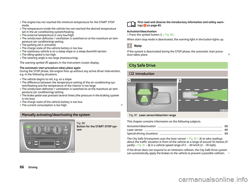
Fig. 80
Button for the START-STOP sys-
tem
First read and observe the introductory information and safety warn-
ings on page 85.
Activation/deactivation
›
Press the symbol button » Fig. 80 .
When start-stop mode is deactivated, the warning light in the button lights up.
Note
If the system is deactivated during the STOP phase, the automatic start proce-
dure takes place.
City Safe Drive
Introduction
Fig. 81
Laser sensor/detection range
This chapter contains information on the following subjects:
Activation/deactivation
88
Laser sensor
88
Special driving situations
89
The City Safe Drivesystem uses the laser sensor » Fig. 81 –
to take readings
about the traffic situation in front of the vehicle at a range of around 10 metres (11
yards) » Fig. 81 –
in a vehicle speed range of 5 - -30 km/h (3 - -19 mph).
If the driver does not respond to an imminent collision, the City Safe Drive system
can automatically apply the brakes to the vehicle to prevent a possible collision.
86Driving
Page 128 of 176
In the following situation, it is possible that the tank cannot be fully filled with
natural gas.
› At very high ambient temperatures. The natural gas refuelling systems have
overheating protection. When the ambient temperature reaches a predefined value, the refuelling system automatically switches off.
› If the refuelling system has been in operation for a longer period, the filling
pressure of the natural gas refuelling system slightly drops.WARNING■ Stop the engine before refuelling.■Always switch off your mobile phone, do not smoke and do not use open
flames when refuelling with natural gas – risk of explosion!■
When refuelling, never get into the vehicle. If you have to get into your vehi-
cle in exceptional cases, close the door and touch a metal surface before you
touch the filling coupling again. This will avoid electrostatic discharges, which
may generate sparks. Sparks can cause a fire during refuelling.
■
Natural gas is highly explosive and flammable. Incorrect refuelling or improp-
er handling of natural gas can cause a fire, an explosion and injuries.
Note
■ The natural gas system of your vehicle is suitable both for fuelling from small
compressors (slow fuelling) and for fuelling from natural gas stations with large
compressors (quick fuelling).■
Noises that occur during refuelling represent no risk.
■
If the vehicle is parked for a longer period of time immediately after refuelling,
the situation may arise in which the pointer of the fuel tank gauge does not indi- cate exactly the same level as was the case immediately after refuelling when theengine is restarted. This is not due to any system leakages but a drop in pressurein the natural gas fuel tank due to technical reasons after a cooling phase directly
after refuelling.
■
For frequent short-haul traffic, especially at low outside temperatures, the vehi-
cle is driven more frequently in petrol mode than in natural gas mode. This is why the petrol tank runs empty faster than the natural gas tank.
■
The capacity of the natural gas tank is about 11 kg, of which about 1.5 kg are a
reserve.
■
The capacity of the petrol tank is about 10 l, of which about 5 l are a reserve.
Automatic switching from CNG to petrol mode
First read and observe the introductory information and safety warn-
ings
on page 123.
The vehicle automatically switches over from CNG mode to petrol mode when the following conditions are met:
› when starting the engine, if the coolant temperature is below 15 °C,
› when the natural gas tank is empty,
› after refuelling with natural gas.
Natural gas as fuel
First read and observe the introductory information and safety warn-ings
on page 123.
Natural gas is an alternative fuel for motor vehicles. Its main component is meth-
ane (CH 4). The rest is carbon dioxide and lower hydrocarbons.
The strict legal requirements for exhaust emissions of motor vehicles are decisive for the current significance of natural gas. In direct comparison to all other fossil
fuels, natural gas is one of the fuels which cause the lowest emissions.
Natural gas is odourless and lighter than air. For safety reasons, it is saturated
with odorous substances, so that is perceived even in very small amounts.
Regular gas system checks
First read and observe the introductory information and safety warn-ings
on page 123.
Every two years, the following inspections must be carried out:
› Check the condition of the fuel filler cap, filler neck and sealing ring, and clean
sealing ring if necessary.
› Check gas system for leaks.
The following checks must be carried out every four years: › Check gas tank mounting for secure attachment and possible damage.
The gas tank must be filled prior to the regular gas system check.
125Inspecting and replenishing
Page 139 of 176
Air bubbles can influence the colour of the indicator. For this reason carefully
knock on the indicator before carrying out the check.
› Black colour – electrolyte level is correct.
› Colourless or light yellow colour – electrolyte level too low, the battery must be
replaced.
Vehicles with a START-STOP system are fitted with a battery control unit for checking the energy level for the recurring engine start.
We recommend that you have the acid level checked regularly by a specialist ga-
rage, especially in the following cases.
› High external temperatures.
› Longer day trips.
› After each charge.
CAUTION
For technical reasons, on vehicles with the description “AGM”, the electrolyte lev-
el cannot be checked.
Note
The battery acid level is also checked regularly by a specialist garage as part of
the inspection service.
Operation in winter
First read and observe the introductory information and safety warn-
ings
on page 134.
The vehicle battery only has a proportion of the starting power in lower tempera-
tures. A discharged vehicle battery may already freeze at temperatures just be-
low 0 °C .
We therefore recommend that you have the battery checked and, if necessary, re-
charged by a specialist garage before the start of the winter.
Charging
First read and observe the introductory information and safety warn-ings
on page 134.
A properly charged vehicle battery is essential for reliably starting the engine.
› Switch off the ignition and all of the electrical components.›Only when performing a “quick-charge”, disconnect both battery cables (first
“negative”, then “positive”).›
Attach the terminal clamps of the charger to the battery terminals (red = “posi- tive”, black = “negative”).
›
Plug the mains cable of the charger into the power socket and switch on thedevice.
›
After charging has been successful: Switch off the charger and remove themains cable from the power socket.
›
Only then disconnect the charger's terminal clamps.
›
Reconnect the cables to the battery (first “positive”, then “negative”).
It is not necessary to disconnect the cables of the battery if you recharge the ve-
hicle battery using low amperages (for example from a mini-charger). Refer to the
instructions of the charger manufacturer .
A charging current of 0.1 multiple of the total vehicle battery capacity (or lower) must be used until full charging is achieved.
It is necessary to disconnect both cables before charging the battery with high
amperages, known as “ rapid charging”.
The vent plugs of the vehicle battery should not be opened for charging.
WARNING“Quick-charging” the vehicle battery is dangerous and requires a special
charger and specialist knowledge.
CAUTION
On vehicles with the START/STOP system, the pole terminal of the charger must
not be connected directly to the negative terminal of the vehicle battery, but only
to the engine earth » page 152, Jump-starting in vehicles with the START-STOP
system .
Note
We therefore recommend that vehicle batteries be rapid charged by a specialist
garage.
136General Maintenance
Page 153 of 176
›Firmly screw the inflation hose 3 onto the tyre inflator bottle 10 clockwise.
The film on the cap is pierced automatically.›
Remove the plug from the inflation hose
3
and plug the open end fully onto
the tyre valve.
›
Hold the bottle
10
with the bottom facing upwards and fill all of the sealing
agent from the tyre inflator bottle into the tyre.
›
Remove the empty tyre inflator bottle from the valve.
›
Screw the valve core back into the tyre valve using the valve remover
1
.
Inflating
›
Screw the tyre inflation hose
5
» Fig. 120 on page 149 of the air compressor
firmly onto the tyre valve.
›
Check that the air release valve
7
is closed.
›
Start the engine and run it in idle.
›
Plug the connector
9
into 12 Volt socket » page 52, 12-volt power socket .
›
Switch on the air compressor with the ON and OFF switch
8
.
›
Allow the air compressor to run until a pressure of 2.0 - 2.5 bar is achieved. Max-
imum run time of 8 minutes » !
›
Switch off the air compressor.
›
If you cannot reach an air pressure of 2.0 – 2.5 bar, unscrew the tyre inflation
hose
5
from the tyre valve.
›
Drive the vehicle 10 metres forwards or backwards to allow the sealing agent to
“distribute” in the tyre.
›
Firmly screw the tyre inflation hose
5
back onto the tyre valve and repeat the
inflation process.
›
If you cannot reach the required tyre inflation pressure here either, this means
the tyre has sustained too much damage. You cannot seal with tyre with the
breakdown kit »
.
›
Switch off the air compressor.
›
Remove the tyre inflation hose
5
from the tyre valve.
Once a tyre inflation pressure of 2.0 – 2.5 bar is achieved, continue the journey at
a maximum speed of 80 km/h (50 mph).
Check the tyre inflation pressure after driving for 10 minutes » page 150.
WARNING■
The tyre inflation hose and air compressor may get hot as the tyre is being
inflated – there is a risk of injury.■
Do not place the hot tyre inflation hose or hot air compressor on flammable
materials – there is a risk of fire.
■
If you cannot inflate the tyre to at least 2.0 bar, this means the damage sus-
tained was too serious. The sealing agent cannot be used to seal the tyre.
Do not drive the vehicle. Seek help from a specialist garage.
CAUTION
Switch off the air compressor after running 8 minutes at the latest – there is a
risk of overheating. Allow the air compressor to cool a few minutes before switch- ing it on again.
Check after 10 minutes' driving
First read and observe the introductory information and safety warn-ings
on page 148.
Check the tyre inflation pressure after driving for 10 minutes!
If the tyre pressure is 1.3 bar or less
›
Do not drive the vehicle! You cannot properly seal with tyre with the break-
down kit.
If the tyre pressure is 1.3 bar or more
›
Adjust the tyre inflation pressure to the correct value (see inside of fuel filler cap).
›
Continue driving carefully to the nearest specialist garage at a maximum speed
of 80 km/h (50 mph).
Jump-starting
Introduction
This chapter contains information on the following subjects:
Jump-starting using the battery from another vehicle
151
Jump-starting in vehicles with the START-STOP system
152
150Do-it-yourself
Page 155 of 176
Negative cable – colour coding in the majority of cases is black.
Jump-starting in vehicles with the START-STOP system
Fig. 122
Engine earth: START-STOP sys-
tem
First read and observe the introductory information and safety warn- ings on page 150.
On vehicles with the START-STOP system, the jump-start cable must only be con-
nected to the engine earthing point » Fig. 122.
Towing the vehicle
Introduction
This chapter contains information on the following subjects:
Front towing eye
153
Vehicles with manual transmission may be towed in with a tow bar or a tow rope
or with the front or rear wheels raised.
Vehicles with automatic transmission may be towed in with a tow bar or a tow
rope or with the front wheels raised. If the vehicle is raised at rear, the automatic
gearbox is damaged!
A tow bar is the safest way of towing a vehicle and also minimises any shocks.
Only use a tow rope if a suitable tow bar is not available.
When towing, the following guidelines must be observed.
Driver of the tow vehicle›Release the clutch particularly gently when starting off or depress the accelera-
tor particularly gently if the vehicle is fitted with an automated transmission.›
On vehicles with a manual transmission, only push down on the accelerator pedal once the rope is taught.
The maximum towing speed is 50 km/h.
Driver of the towed vehicle
›
Switch on the ignition so that the steering wheel is not locked and so that the turn signal lights, horn, windscreen wipers and windscreen washer system can
be used.
›
Take the vehicle out of gear or move the selector lever into position N if the ve-
hicle is fitted with an automated transmission.
Please note that the brake servo unit and power steering only operate if the en-
gine is running. If the engine is not running, significantly more physical force is re-
quired to depress the brake pedal and steer the vehicle.
If using a tow rope, ensure that it is always kept taught.
CAUTION
■ Do not tow start the engine – there is a risk of damaging the engine and the
catalytic converter. The battery from another vehicle can be used as a jump-start
aid » page 150 , Jump-starting .■
If the gearbox no longer contains any oil because of a defect, your vehicle must
only be towed with the drive wheels raised clear of the ground or on a special
breakdown vehicle or trailer.
■
The vehicle must be transported on a special breakdown vehicle or trailer if it is
not possible to tow in the vehicle in the way described or if the towing distance is greater than 50 km.
■
To protect both vehicles when tow-starting or towing, the tow rope should be
elastic. Thus one should only use plastic fibre rope or a rope made out of a simi-
larly elastic material.
■
While towing, take care to avoid impermissibly high tensile forces or jerky loads.
There is always a risk of excessive stresses and damage resulting at the points to
which you attach the tow rope or tow bar when you attempt to tow a vehicle which is not standing on a paved road.
■
Attach the tow rope or the tow bar only to the towing eye » page 153 .
152Do-it-yourself
Page 156 of 176
Note■We recommend using a tow rope from ŠKODA Original Accessories, which is
available from a ŠKODA Partner.■
Towing another vehicle requires a certain amount of practice. Both drivers
should be familiar with the particular points about towing a vehicle. Unskilled
drivers should not attempt to tow in another vehicle or to be towed in.
■
When towing, respect the national legal provisions, especially those which re-
late to the identification of the towing vehicle and the vehicle being towed.
■
The tow rope must not be twisted as it may in certain circumstances result in
the front towing eye being unscrewed out of your vehicle.
Front towing eye
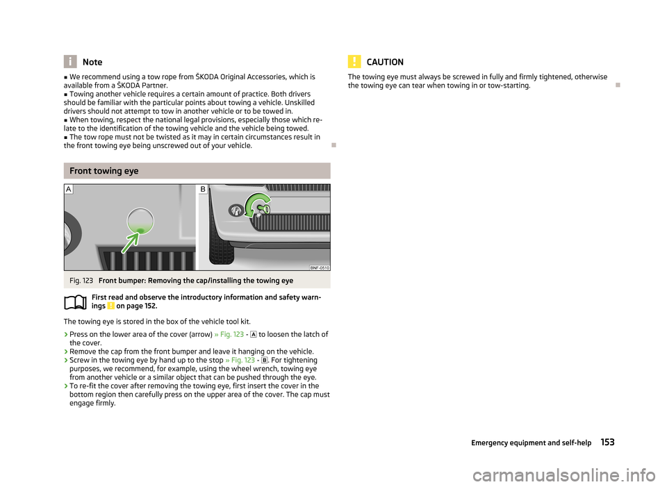
Fig. 123
Front bumper: Removing the cap/installing the towing eye
First read and observe the introductory information and safety warn- ings
on page 152.
The towing eye is stored in the box of the vehicle tool kit.
›
Press on the lower area of the cover (arrow) » Fig. 123 -
to loosen the latch of
the cover.
›
Remove the cap from the front bumper and leave it hanging on the vehicle.
›
Screw in the towing eye by hand up to the stop » Fig. 123 -
. For tightening
purposes, we recommend, for example, using the wheel wrench, towing eye
from another vehicle or a similar object that can be pushed through the eye.
›
To re-fit the cover after removing the towing eye, first insert the cover in the
bottom region then carefully press on the upper area of the cover. The cap must
engage firmly.
CAUTIONThe towing eye must always be screwed in fully and firmly tightened, otherwise
the towing eye can tear when towing in or tow-starting.
153Emergency equipment and self-help
Page 159 of 176
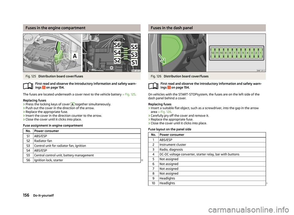
Fuses in the engine compartmentFig. 125
Distribution board cover/fuses
First read and observe the introductory information and safety warn-
ings
on page 154.
The fuses are located underneath a cover next to the vehicle battery » Fig. 125.
Replacing fuses
›
Press the locking keys of cover
A
together simultaneously.
›
Push out the cover in the direction of the arrow.
›
Replace the appropriate fuse.
›
Insert the cover in the direction counter to the arrow.
›
Close the cover until it clicks into place.
Fuse assignment in engine compartment
No.Power consumerS1ABS/ESPS2Radiator fanS3Control unit for radiator fan, ignitionS4ABS/ESPS5Central control unit, battery managementS6Ignition lock, starter
Fuses in the dash panelFig. 126
Distribution board cover/fuses
First read and observe the introductory information and safety warn-
ings
on page 154.
On vehicles with the START-STOPsystem, the fuses are on the left side of the
dash panel behind a cover.
Replacing fuses
›
Insert a suitable flat object, such as a screwdriver, into the gap in the arrow area » Fig. 126 .
›
Carefully pry off the cover and remove it.
›
Replace the appropriate fuse.
›
Close the cover until it clicks into place.
Fuse layout on the panel side
No.Power consumer1ABS/ESP2Instrument cluster3Radio, diagnosis4DC-DC voltage converter, starter relay, bar with buttons5Not assigned6Not assigned7Not assigned8Not assigned9Headlights10Headlights 156Do-it-yourself
Page 167 of 176
Index
Numbers and Symbols
12-volt power socket
52
A
Abroad Driving abroad
79
Unleaded petrol79
ABS81
Warning light19
Accessories110
Adjusting Exterior mirrors
41
Interior mirror40
Seat43
Steering wheel66
Adjusting the seats91
Aerial114
Air-conditioning system Air outlet vents
57
Airbag98
Deactivating101
Deactivating the front passenger airbag102
Deployment98
Front airbag99
Modifications and damage to the airbag system112
Side airbag Head-Thorax100
Airbag system98
Air conditioning system59
Control elements60
Recirculated air mode61
Air outlet vents57
Antilock Braking System81
Artificial leather120
Ash tray51
Assist systems80
ABS19, 81
City Safe Drive86
Cruise Control System83
EDS81
ESC18, 80
Parking aid81
START-STOP85
TC81
Traction Control System (TCS)19
Visual parking system82
Automated transmission71
Lever control71
Automatic gearbox Operational faults
73
Tiptronic72
Automatic load deactivation137
Automatic transmission Kick-down
72
Starting-off and driving72
Avoiding damage to the vehicle Driving through water
78
Avoiding damage to your vehicle78
B
Bag hooks
47
Belts94
Belt tensioners97
Bonnet Closing
128
Opening128
Boot Class N1 vehicles
47
Boot lid Automatic locking
29
Brake assist80
Brake booster69
Brake fluid133
Changing134
Checking133
Brakes Brake assist systems80
Brake booster69
Brake fluid133
Handbrake70
Running in74
Warning lights16
Braking Information on braking
69
Breakdown kit149
Bulbs In the tail light
159
Replacing157
Button in the driver's door Electrical power windows
30
C
Car computer see multifunction display
13
Carrier49
Cavity protection117
Central locking button27
Central locking system25
lock26
unlock26
Changing Brake fluid
134
Engine oil131
Fuses on the underside of the dash panel154
Wheels145
Changing a wheel Follow-up work
146
Preliminary work145
Remove and attaching a wheel146
Charging a vehicle battery136
Checking Battery electrolyte level
135
Brake fluid133
Coolant132
Engine oil131
164Index