power steering SKODA OCTAVIA 2012 2.G / (1Z) User Guide
[x] Cancel search | Manufacturer: SKODA, Model Year: 2012, Model line: OCTAVIA, Model: SKODA OCTAVIA 2012 2.G / (1Z)Pages: 222, PDF Size: 13.52 MB
Page 128 of 222

NoteIf the front passenger front airbag is deactivated » page 151 the belt tensioning
function for the front passenger seat is switched off.
Lane Assist
Introduction
This chapter contains information on the following subjects:
Operating principle
126
Explanations of situations
127
Information for the driver
128WARNING■ Lane Assist only operates as a support- it does absolve the driver of the re-
sponsibility to maintain full control over the vehicle's steering.■
Lane Assist only makes the driver away that the vehicle is approaching the
line between two lanes by means of a steering intervention. The driver retains
responsibility at all times for keeping the vehicle within the lane.
■
Lane Assist can help you keep the vehicle within the lane. However, it does
not steer the vehicle for you. The driver retains full responsibility for steering at all times.
■
The camera need not be able to detect all lane lines. A steering intervention
can only be made when the vehicle approaches a detected line between lanes.
■
Some objects on the road may be incorrectly detected as lines. As a result,
an incorrect steering intervention may take place.
■
The function of adaptive lane guidance Assist system may be restricted
when driving e.g. over rutted roads, on a slope, or if there are lateral winds.
■
Do not use the Assist system in poor weather, e.g. black ice, fog, heavy rain -
risk of accident!
WARNINGThe camera's powers of detection may be limited by a range of external influ-
ences. In this case, the Assist system may not be able to detect the line cor-
rectly, if at all. The camera's powers of detection may be limited, e.g. in the fol- lowing:■
in poor visibility conditions, e.g. fog, heavy rain, thick snowfall;
■
when dazzled by the sun;
■
when dazzled by oncoming traffic;
■
by vehicles ahead;
■
when the camera viewing range is obstructed by an obstacle.
CAUTION
Do not attach any stickers or similar objects to the windscreen to avoid impairing
the functions of the Assist system.
Operating principle
Fig. 117
Windscreen: Camera viewing
window for Lane Assist
First read and observe the introductory information and safety warn- ings on page 126.
Lane Assist (in the following referred to as the system) detects the lines between
lanes using data obtained from the camera (continuous and interrupted) » Fig. 117.
When the vehicle approaches a detected line between lanes, the system makes a
light movement of the steering wheel in the opposite direction to the boundary
line. This corrective steering intervention can be overridden at any time.
The strength of the steering movement can be activated/deactivated in the Info-
tainment » operating instructions for Infotainment , chapter Setting vehicle sys-
tems (CAR button) .
126Using the system
Page 131 of 222
Automatic gearbox
Automatic transmission
Introduction
This chapter contains information on the following subjects:
Introductory information
129
Starting-off and driving
130
Selector lever positions
130
Manual shifting of gears (Tiptronic)
131
Selector lever lock
131
Kickdown function
132
Dynamic shift programme
132
Emergency programme
132
Selector lever-emergency unlocking
133WARNING■ Do not depress the accelerator if changing the position of the selector lever
when the vehicle is stationary and the engine is running – risk of accident!■
Never move the selector lever into position R or P when driving – risk of an
accident!
■
When the vehicle is stationery and the engine is running, stopping the vehi-
cle requires you pressing the brake pedal in all selector lever settings. When
the engine is idling, the power transmission is never completely interrupted -
the vehicle creeps.
■
The selector lever must be placed into position P and the handbrake firmly
applied before the bonnet can be opened and work on the running engine can
be completed – risk of accident! The safety guidelines must always be ob-
served » page 169 , Engine compartment .
■
If stopping on a hill (downhill gradient), never try to maintain the vehicle sta-
tionary with the gear engaged by means of the accelerator pedal, i.e. by let-
ting the clutch slip - This can lead to overheating of the clutch. If there is a risk
of overheating of the clutch due to overload, the clutch is opened automati-
cally and the vehicle rolls backward – risk of accident!
WARNING (Continued)■ If you have to stop on a slope, depress and hold the brake pedal to prevent
the vehicle from rolling back.■
On a smooth or slippery road surface using the kickdown function can cause
the driven wheels to spin – risk of skidding!
Note
If the driving mode Sport or Eco » page 124 is selected and the selector lever is in
position D/S, the gearbox is automatically set to mode S or E. The mode is indica-
ted in the instrument cluster display » Fig. 120 on page 130.
Introductory information
First read and observe the introductory information and safety warn-
ings
on page 129.
Starting
The engine can only be started when the selector lever is in position P or N .
When the steering is locked, when the ignition is turned on or off, or when start-
ing the engine, If the selector lever is not in the positions P or N, the following
message appears in the instrument cluster display Move the selector lever to Po-
sition P/N! or ENGAGE N OR P .
Shifting gears
Shifting up and down through the gears is performed automatically. The gearbox
can also be switched to Tiptronic mode. This mode makes it possible for you to
also shift gears manually » page 131.
If the selector lever position N is accidentally selected while driving, it is first nec-
essary to release pressure on the accelerator pedal and wait for the idling speed of the engine to be reached before the selector lever can be engaged in the driveposition.
At temperatures below -10 °C the engine can only be started in the selector lever position P.
Parking
When parking on a level road surface, it suffices to engage selector lever position
P .
129Automatic gearbox
Page 133 of 222
N – Neutral
The brake pedal must be depressed to move the selector lever out of the position
N (if the lever is in this position for longer than 2 seconds) into the position D/S or
R when the vehicle is travelling at less than 5 km/h and the ignition is switched
on.D/S
- mode for driving forward (Normal program)/mode for driving forward
(Sport program)
The system switches from one mode to the other by moving the selector lever in- to the spring-tensioned position » Fig. 120 .
In the D or S mode, the forward gears are shifted up and down, depending on the
selected driving mode, engine load, driving speed and dynamic shifting program.
In the S mode, shifting up later into a higher gear makes it possible to fully exploit
the power potential of the engine. The gearbox also then shifts down at higher engine speeds as in the position D.
The brake pedal must be depressed to move the selector lever into position D/S
from Nwhen the vehicle is travelling at less than 5 km/h.
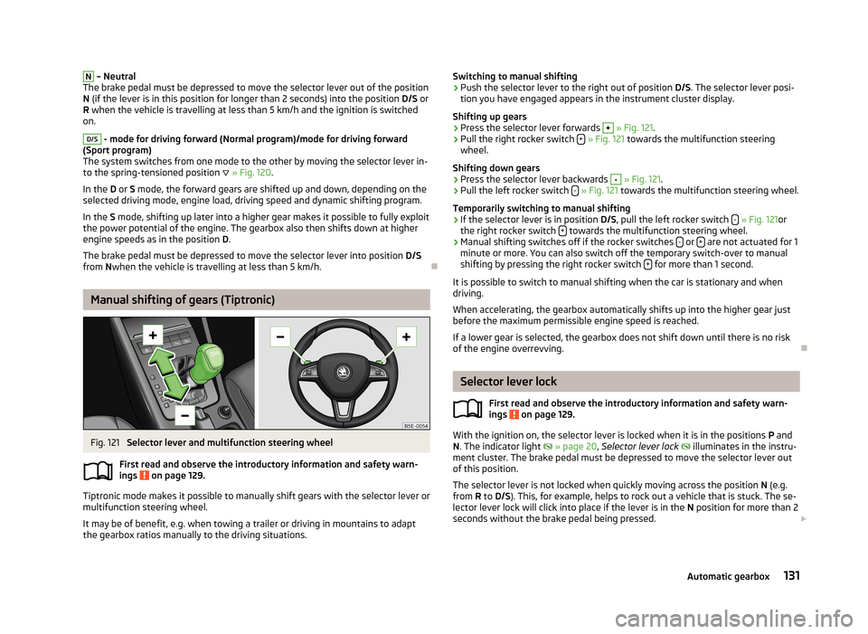
Manual shifting of gears (Tiptronic)
Fig. 121
Selector lever and multifunction steering wheel
First read and observe the introductory information and safety warn-
ings
on page 129.
Tiptronic mode makes it possible to manually shift gears with the selector lever or
multifunction steering wheel.
It may be of benefit, e.g. when towing a trailer or driving in mountains to adapt
the gearbox ratios manually to the driving situations.
Switching to manual shifting›Push the selector lever to the right out of position D/S. The selector lever posi-
tion you have engaged appears in the instrument cluster display.
Shifting up gears›
Press the selector lever forwards
+
» Fig. 121 .
›
Pull the right rocker switch +
» Fig. 121 towards the multifunction steering
wheel.
Shifting down gears
›
Press the selector lever backwards
-
» Fig. 121 .
›
Pull the left rocker switch -
» Fig. 121 towards the multifunction steering wheel.
Temporarily switching to manual shifting
›
If the selector lever is in position D/S, pull the left rocker switch -
» Fig. 121 or
the right rocker switch + towards the multifunction steering wheel.
›
Manual shifting switches off if the rocker switches
- or + are not actuated for 1
minute or more. You can also switch off the temporary switch-over to manual shifting by pressing the right rocker switch +
for more than 1 second.
It is possible to switch to manual shifting when the car is stationary and when
driving.
When accelerating, the gearbox automatically shifts up into the higher gear just before the maximum permissible engine speed is reached.
If a lower gear is selected, the gearbox does not shift down until there is no risk
of the engine overrevving.
Selector lever lock
First read and observe the introductory information and safety warn-ings
on page 129.
With the ignition on, the selector lever is locked when it is in the positions P and
N . The indicator light
» page 20 , Selector lever lock
illuminates in the instru-
ment cluster. The brake pedal must be depressed to move the selector lever out
of this position.
The selector lever is not locked when quickly moving across the position N (e.g.
from R to D/S ). This, for example, helps to rock out a vehicle that is stuck. The se-
lector lever lock will click into place if the lever is in the N position for more than 2
seconds without the brake pedal being pressed.
131Automatic gearbox
Page 137 of 222
INDUSTRY CANADA Statements
Le présent appareil est conforme aux CNR d'Industrie Canada applicables aux
appareils radio exempts de licence. L'exploitation est autorisée aux deux
conditions suivantes : (1) l'appareil ne doit pas produire de brouillage, et (2)
l'utilisateur de l'appareil doit accepter tout brouillage radioélectrique subi, même
si le brouillage est susceptible d'en compromettre le fonctionnement.
Phonebox
The vehicle body partially interferes with the telephone signal and makes use of
the mobile telephone somewhat more difficult in regions with a weak signal. The
current consumption and the telephone battery discharges more quickly.
To reduce the effects of these defects, an induction plate is located on the bot-
tom of the stowage compartment in the centre console » Fig. 68 on page 74. The
induction plate generates a induction field for the telephone signal which is direc- ted to the plate on the roof aerial where it is amplified.
The mobile phone kept in the stowage compartment with the underside on the
induction plate can use a signal boosted by around 20 %.
As a result:
› the sending and receiving power of the telephone is improved;
› the discharge of the phone battery is reduced;
› the electromagnetic radiation is reduced in the vehicle interior.
Multimedia
Operating Infotainment from the multifunction steering wheel
Fig. 123
Multifunction steering wheel: Control buttons and dials
Buttons and dials are located on the multifunction steering wheel for operating
some Infotainment functions » Fig. 123.
The buttons and dials operate the functions for the current operating mode of the Infotainment.Button/ adjust- ment
wheel
ActionRadio, traffic report, TVAudio, Video, DVD, DVD menuNavigation
1Press brieflyChange audio source, change frequency range1Press button for a
long period of timeChange the audio source and call up the last context status (e.g. the last radio station that was played or title a)
)2Press brieflySwitch off/on tone b)
135Communication
Page 138 of 222
Button/adjust- ment
wheel
ActionRadio, traffic report, TVAudio, Video, DVD, DVD menuNavigation
2Turn upwardsIncrease volume2Turn downwardsDecrease volume3
Press brieflyChanging to the next stored radio station
Changing to the next stored traffic information Interrupting the traffic reportChange to the next title a)
Change to the next chapter c)
Change to the first chapter d)Function based on the current audio
source3Press button for a
long period of timeInterruption of the traffic reportFast forward a)4
Press brieflyChanging to the previously stored radio station
Changing to the previously stored traffic information Interrupting the traffic reportChange to previous title a)
Change to previous chapter c)4Press button for a
long period of timeInterruption of the traffic reportFast rewind a)5Press brieflyInterruption of the traffic reportwithout functionRepeats the last navigation announce-
ment5
Turn upwardsDisplay of the stored/accessible stationsScroll upwards
Interruption of the traffic reportChange to previous title a)
Change to previous chapter c)
Displays list of last destinations
5
Turn downwardsDisplay of the stored/accessible stations
Scroll downwards
Interruption of the traffic reportChange to the next title a)
Change to the next chapter c)
Change to the first chapter d)6Press brieflyCall up main menu on information displaya)
Does not apply for AUX.
b)
The tone is switched on again by pressing one of the buttons
1
,
3
or
4
and the adjustment wheel
2
is rotated.
c)
Applies for DVD.
d)
Applies for the DVD menu.
Note■
If the ignition and the side lights are switched on, the buttons and dials on the
multifunction steering wheel are also illuminated.■
The set of loudspeakers in the vehicle is matched to a power output of the Info-
tainment of 4x20 W.
■
Vehicles with the CANTON sound system equipment are fitted with a loud-
speaker set including centre speaker and bass. The loudspeaker set is tuned with
a external 10 channel amp for a total output of 570 W.
136Using the system
Page 198 of 222
›If the engine does not start, terminate the attempt to start the engine after
10 seconds and wait for about 30 seconds before repeating the process.›
Disconnect the cables in exactly the reverse order to the one described above.
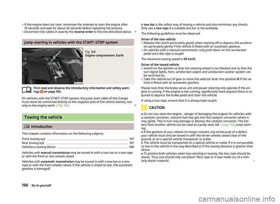
Jump-starting in vehicles with the START-STOP system
Fig. 168
Engine compartment: Earth
First read and observe the introductory information and safety warn-
ings on page 195.
On vehicles with the START-STOP system, the jump-start cable of the charger
must never be connected directly to the negative pole of the vehicle battery, but
only to the engine earth » Fig. 168.
Towing the vehicle
Introduction
This chapter contains information on the following subjects:
Front towing eye
197
Rear towing eye
197
Vehicles a towing device
198
Vehicles with manual transmission may be towed in with a tow bar or a tow rope
or with the front or rear wheels raised.
Vehicles with automatic transmission may be towed in with a tow bar or a tow
rope or with the front wheels raised. If the vehicle is raised at rear, the automatic
gearbox is damaged!
A tow bar is the safest way of towing a vehicle and also minimises any shocks.
Only use a tow rope if a suitable tow bar is not available.
The following guidelines must be observed.
Driver of the tow vehicle›
Release the clutch particularly gently when starting off or depress the accelera-
tor particularly gently if the vehicle is fitted with an automatic gearbox.
›
On vehicles with a manual transmission, only push down on the accelerator pedal once the rope is taught.
The maximum towing speed is 50 km/h.
Driver of the towed vehicle
›
Switch on the ignition so that the steering wheel is not blocked and so that the
turn signal lights, horn, windscreen wipers and windscreen washer system can be switched on.
›
Take the vehicle out of gear or move the selector lever into position N if the ve-
hicle is fitted with an automatic gearbox.
Please note that the brake servo unit and power steering only operate if the en-
gine is running. If the engine is not running, significantly more physical force is re- quired to depress the brake pedal and steer the vehicle.
If using a tow rope, ensure that it is always kept taught.
CAUTION
■ Do not tow start the engine - danger of damaging the engine! On vehicles with
a catalytic converter, unburnt fuel may get into the catalytic converter where it
may ignite. This in turn may damage or destroy the catalytic converter. The bat-
tery from another vehicle can be used as a jump-start aid » page 195, Jump-start-
ing .■
If the gearbox of your vehicle no longer contains any oil because of a defect,
your vehicle must only be towed in with the driven wheels raised clear of the
ground, or on a special vehicle transporter or trailer.
■
The vehicle must be transported on a special vehicle or trailer if it is not possible
to tow in the vehicle in the way described or if the towing distance is greater than
50 km.
■
To protect both vehicles when tow-starting or towing, the tow rope should be
elastic. Thus one should only use plastic fibre rope or a rope made out of a simi-
larly elastic material.
196Do-it-yourself
Page 202 of 222
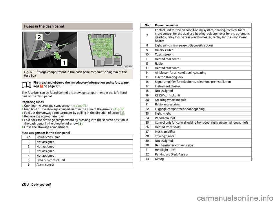
Fuses in the dash panelFig. 171
Storage compartment in the dash panel/schematic diagram of the
fuse box
First read and observe the introductory information and safety warn-
ings
on page 199.
The fuse box can be found behind the stowage compartment in the left-hand
part of the dash panel.
Replacing fuses
›
Opening the stowage compartment » page 73.
›
Grab hold of the stowage compartment in the area of the arrows » Fig. 171.
›
Fold out the stowage compartment by pulling in the direction of arrow
1
.
›
Replace the appropriate fuse.
›
Fold back the stowage compartment by pressing into the secured position in
the dash panel in the direction of arrow
2
.
›
Close the stowage compartment.
Fuse assignment in the dash panel
No.Power consumer1Not assigned2Not assigned3Not assigned4Not assigned5Data bus control unit6Alarm sensorNo.Power consumer
7
Control unit for the air conditioning system, heating, receiver for re-
mote control for the auxiliary heating, selector lever for the automatic gearbox, relay for the rear window heater, replay for the windscreen
heater8Light switch, rain sensor, diagnostic socket9Haldex clutch10Touchscreen11Heated rear seats12Radio13Heated rear seats14Air blower for air conditioning,heating15Electric steering lock16Signal amplifier for telephone, telephone preinstallation17Instrument cluster18Not assigned19KESSY control unit20Steering wheel module21Radio accessories22Luggage compartment door opening23Light - right24Panorama roof25Control unit for central locking front door right, power windows - left26Heated front seats27Music amplifier28Towing device29Not assigned30Belt tensioner - driver's side31Headlight - left32Parking aid (Park Assist)33Airbag 200Do-it-yourself
Page 214 of 222
Index
A
ABS Function
113
Warning light17
Accessories165
Active driver-steering recommendation (DSR)112
Adjusting Exterior mirror
58
Interior mirror57
Adjusting seats139
Adjustment Seat
60
Aerial160
see Radio reception162
Airbag146
Deployment146
Front airbag147
Head airbag150
Knee airbag148
Side airbag149
Airbag system146
Air conditioning system Air outlets
82
Climatronic86
Manual air conditioning system84
Air outlets82
Alarm35
Anti-theft alarm system35
Antilock brake system113
Armrest Front
76
rear64
Ashtray70
Assist systems ABS
17, 113
Cruise control systems (CCS)119
EDL114
ESC17, 112
Headlight assist47
Lane Assist126
Park Assist116
Parking aid114
ProActive passenger protection125
Select driving mode124
START/STOP121
TCS16, 113
Auto Check Control12
Automatic driving lamp control45
Automatic gearbox Dynamic shift programme
132
Emergency programme132
Kickdown132
Selector lever-emergency unlocking133
Selector lever lock131
Selector lever positions130
Starting-off and driving130
Tiptronic131
Automatic load deactivation180
Automatic transmission129
Auxiliary heating and cooling system Switching on/off
89
Auxiliary heating (auxiliary heating and ventila- tion)
88
setting90
B
Ball rod Check attachment
108
installing107
Ready position107
removing108
Battery Replacing the battery in the remote control(aux-
iliary heating)
91
Before setting off138
Belt tensioners145
Bonnet Closing171
Opening171
Boot Cover
67
Fastening elements65
Fixing of the floor covering66
Light65
see Boot lid37
Boot lid37
Automatic locking38
Brake booster97
Brake fluid Checking
175
Brake pads Indicator light
20
Brakes Brake assist systems
112
Brake booster97
Handbrake98
Running in100
Warning light14
Braking Brake fluid
175
Information for braking97
Breakdown kit192
Break recommendation see Fatigue detection
27
Bulbs Replacing
202
Button in the driver's door Electrical power windows
38
C
Car computer see Multifunction display
22
Car jack188
Carrier68
Catalytic converter100
Central locking button32
212Index
Page 217 of 222
Hazard warning light system49
Headlight beam adjustment44
Headlight flasher45
Main beam45
parking light45
Parking light44
Rear fog light48
Replacing bulbs202
Tourist light46
Turn signal light45
Lights Low beam
44
switching on and off44
Warning lights12
Loads207
Locking Remote control
32
Locking and unlocking from the inside32
Lock the vehicle Keys
31
Luggage compartment Emergency unlocking
38
Fixing nets66
Folding double hooks66
Unlocking the luggage compartment lid38
M
Mirror Exterior mirror
58
Vanity53
Mobile phone134
Multicollision brake112
Multifunction display Functions
22
Memory22
Select data22
Multimedia135
AUX137
MEDIA IN137
USB137
N
Nets
66
O
Oil refer to Engine oil
172
Onboard computer see Multifunction display
22
Operation in winter De-icing windows
162
Diesel fuel169
Vehicle battery179
Outside temperature21
Overview Engine compartment
172
Warning lights12
P
Paint see Paint damage
161
Paint damage161
Parking automatic brake assist
116
Manoeuvring out of a parallel parking space116
Park Assist116
Parking aid114
Parking ticket holder80
Passive Safety138
Pedals99
Petrol refer to Fuel
168
Polishing the paintwork refer to Taking care of your vehicle
161
Power sockets 12 V
71
230 V71
Power steering93
Power windows Button in the front passenger door40
Preservation refer to Taking care of your vehicle
161
ProActive passenger protection125
R
Radiator fan
175
Radio reception Aerial
162
Functional fault162
Raise vehicle191
Rear mirror56
Exterior mirror58
Interior mirror57
Rear seats Seat backrest
63
Rear window - heating52
Recirculated air mode Climatronic
87
Manual air conditioning system85
Recommended gear21
Refuelling167
Fuel167
Regulation Headlight beam
44
Remote control32
Auxiliary heating (auxiliary heating)90
Synchronisation process33
Remote control key Replacing the battery
28
Replacement of parts165
replacing Vehicle battery
179
Replacing bulbs
202
Fuses199
The rear window wiper blade56
Wiper blades56
215Index