tow SKODA RAPID 2016 1.G User Guide
[x] Cancel search | Manufacturer: SKODA, Model Year: 2016, Model line: RAPID, Model: SKODA RAPID 2016 1.GPages: 184, PDF Size: 27.06 MB
Page 58 of 184
Fog lights/rear fog lightFig. 43
Light switch – switch on front
and rear fog light
Read and observe on page 53 first.
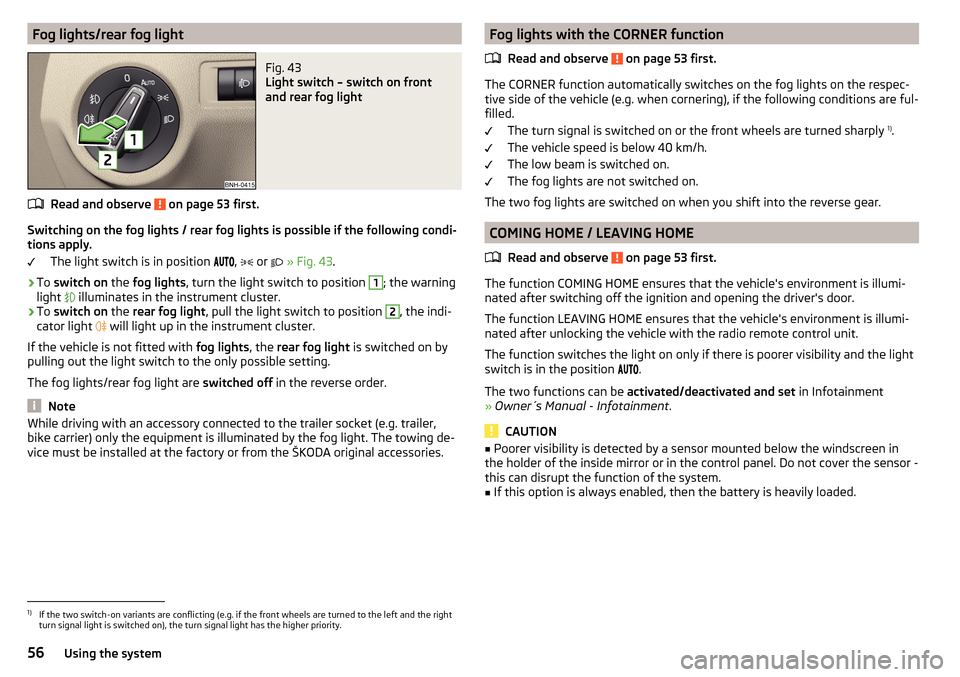
Switching on the fog lights / rear fog lights is possible if the following condi-
tions apply.
The light switch is in position ,
or
» Fig. 43 .
›
To switch on the fog lights , turn the light switch to position
1
; the warning
light illuminates in the instrument cluster.
›
To
switch on the rear fog light , pull the light switch to position
2
, the indi-
cator light will light up in the instrument cluster.
If the vehicle is not fitted with fog lights, the rear fog light is switched on by
pulling out the light switch to the only possible setting.
The fog lights/rear fog light are switched off in the reverse order.
Note
While driving with an accessory connected to the trailer socket (e.g. trailer,
bike carrier) only the equipment is illuminated by the fog light. The towing de-
vice must be installed at the factory or from the ŠKODA original accessories.Fog lights with the CORNER function
Read and observe
on page 53 first.
The CORNER function automatically switches on the fog lights on the respec-tive side of the vehicle (e.g. when cornering), if the following conditions are ful-
filled.
The turn signal is switched on or the front wheels are turned sharply 1)
.
The vehicle speed is below 40 km/h.
The low beam is switched on.
The fog lights are not switched on.
The two fog lights are switched on when you shift into the reverse gear.
COMING HOME / LEAVING HOME
Read and observe
on page 53 first.
The function COMING HOME ensures that the vehicle's environment is illumi-
nated after switching off the ignition and opening the driver's door.
The function LEAVING HOME ensures that the vehicle's environment is illumi-
nated after unlocking the vehicle with the radio remote control unit.
The function switches the light on only if there is poorer visibility and the light
switch is in the position .
The two functions can be activated/deactivated and set in Infotainment
» Owner´s Manual - Infotainment .
CAUTION
■
Poorer visibility is detected by a sensor mounted below the windscreen in
the holder of the inside mirror or in the control panel. Do not cover the sensor -
this can disrupt the function of the system.■
If this option is always enabled, then the battery is heavily loaded.
1)
If the two switch-on variants are conflicting (e.g. if the front wheels are turned to the left and the right
turn signal light is switched on), the turn signal light has the higher priority.
56Using the system
Page 61 of 184
WARNINGNo objects should be attached to the sun visor that could restrict the view
or endanger the vehicle occupants during sudden braking or in a collision.
Windscreen and rear window
Fig. 47
Buttons for the windscreen and
rear window heating
Read and observe on page 59 first.
The heating for quick defrosting and ventilation of the windscreen / rear win-
dow.
The heating only works when the engine is running.
Buttons for the heating (depending on vehicle equipment) » Fig. 47
Switching the windscreen heater on/off
Switch on/off the rear window heating
When the heater is switched on, a lamp illuminates inside the button.
The heating automatically switches off after ten minutes.
Note
■ If the on-board voltage decreases, the heating switches off automatically
» page 131 , Automatic shutdown of consumers - vehicle battery discharge
protection .■
If the light is flashing inside the button, there is no heating because the bat-
tery charge is too low.
Sun visors frontFig. 48
Fold down the cover / swivel cover to the door and slide the mir-
ror cover
Read and observe
on page 59 first.
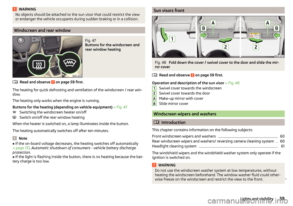
Operation and description of the sun visor » Fig. 48
Swivel cover towards the windscreen
Swivel cover towards the door
Make-up mirror with cover
Slide mirror cover
Windscreen wipers and washers
Introduction
This chapter contains information on the following subjects:
Front windscreen wipers and washers
60
Rear windscreen wipers and washers/ reversing camera cleaning system
60
Headlight cleaning system
61
The windshield wipers and the windshield washer system only operate if the
ignition is switched on.
WARNINGDo not use the windscreen washer system at low temperatures, without
heating the windscreen beforehand. The window washer fluid could other-
wise freeze on the windscreen and restrict the view to the front. 12AB59Lights and visibility
Page 64 of 184
Exterior mirrorsFig. 52
Exterior mirror operation: mechanical / electrical
Read and observe
on page 61 first.
The outer mirror surfaces are (depending on the vehicle specification) mechan-
ically or electrically adjustable.
›
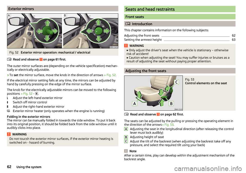
To set the mirror surface, move the knob in the direction of arrows » Fig. 52.
If the electrical mirror setting fails at any time, the mirrors can be adjusted by
hand by carefully pressing on the edge of the mirror surface.
The knob for the electrically adjustable mirrors can be moved to the following
positions » Fig. 52 -
.
Adjust the left-hand exterior mirror
Switch off mirror control
Adjust the right-hand exterior mirror
Exterior mirror heater (only operates when the engine is running)
Folding in the exterior mirrors
The mirror can be manually folded in towards the side window. To put it back
into its original position, it should be folded back from the side window until it
audibly clicks into place.
WARNINGDo not toucsh the exterior mirror surfaces, if the exterior mirror heating is
switched on - hazard of burning.Seats and head restraints
Front seats
Introduction
This chapter contains information on the following subjects:
Adjusting the front seats
62
Setting the armrest height
63WARNING■ Only adjust the driver's seat when the vehicle is stationary – otherwise
risk of accident!■
Caution when adjusting the seat! You may suffer injuries or bruises as a
result of adjusting the seat without paying proper attention.
Adjusting the front seats
Fig. 53
Control elements on the seat
Read and observe on page 62 first.
The seats can be adjusted by the pulling or pressing the operating element in
the direction of the arrows » Fig. 53.
Adjusting the seat in the longitudinal direction (after releasing the control
lever must lock audibly)
Adjusting height of seat
Adjust the tilt of the backrest (when adjusting the backrest take off any
pressure, and select the required tilt using your back)
Note
After a certain time, play can develop within the adjustment mechanism of the
backrest angle.ABC62Using the system
Page 68 of 184

Useful features
Interior fittings
Introduction
This chapter contains information on the following subjects:
Ticket holder
66
stowage compartments in the doors
67
Storage compartment in the centre console
67
USB and AUX input
67
Storage compartment on the dashboard
67
Cup holders
68
Waste container
68
Cigarette lighter
69
Ashtray
69
12-volt socket
70
Multimedia holder
70
Storage compartment in the front arm rest
71
Glasses compartment
71
Storage compartment on the front passenger side
71
Storage compartment for umbrella
72
Clothes hook
72
Storage pockets on the backs of the front seats
72
Storage pockets on the inner sides of the front seats
72WARNING■ Do not place anything on the dashboard. These objects might slide or fall
down when driving and may distract you from concentrating on the traffic –
risk of accident!■
Make sure that while driving no objects can enter the driver's footwell -
they could cause an accident!
■
Do not carry any objects on the front passenger seat, except objects de-
signed for this purpose (e.g. child seats) – risk of accident!
■
No objects should be placed in the storage compartments nor in the
drinks holders; the vehicle occupants could be endangered if there is sud-
den braking or the vehicle collides with something.
WARNING (Continued)■ For safety reasons, lockable storage compartments should be closed
while driving - there is a risk of injury from the opened lid or through the
loose objects in the compartment.■
Make sure no objects protrude from the storage compartments - danger
of injury!
■
Do not exceed the permissible loads for the storage compartments and
pockets - risk of injury and risk of damage to the compartments and pock-
ets!
■
Ash, cigarettes, cigars and the like should only be stored in the ashtray -
danger of fire/burns!
■
The storage compartments, multimedia holder and waste container are
not a substitute for the ashtray and must not be used for such purposes –
risk of fire!
CAUTION
Do not place any large or sharp objects in the storage compartments and pock-
ets - there is a risk of damage to the compartments and pockets.
Ticket holder
Fig. 61
Ticket holder
Read and observe and on page 66 first.
The ticket holder » Fig. 61 is provided for the holding and displaying e.g. car
park tickets.
66Using the system
Page 69 of 184
stowage compartments in the doorsFig. 62
Storage compartments: in the front door/in the rear door
Read and observe
and on page 66 first.
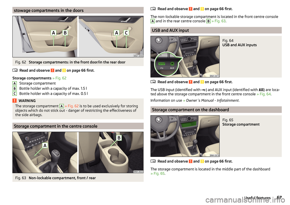
Storage compartments » Fig. 62
Storage compartment
Bottle holder with a capacity of max. 1.5 l
Bottle holder with a capacity of max. 0.5 l
WARNINGThe storage compartment A » Fig. 62 is to be used exclusively for storing
objects which do not stick out - danger of restricting the effectiveness of
the side airbags.
Storage compartment in the centre console
Fig. 63
Non-lockable compartment, front / rear
ABCRead and observe and on page 66 first.
The non-lockable storage compartment is located in the front centre console
A
and in the rear centre console
B
» Fig. 63 .
USB and AUX input
Fig. 64
USB and AUX inputs
Read and observe and on page 66 first.
The USB input (identified with
) and AUX input (identified with
) are loca-
ted above the storage compartment in the front centre console » Fig. 64.
Information on use » Owner´s Manual - Infotainment .
Storage compartment on the dashboard
Fig. 65
Storage compartment
Read and observe and on page 66 first.
The storage compartment is located in the middle part of the dashboard
» Fig. 65 .
67Useful features
Page 72 of 184
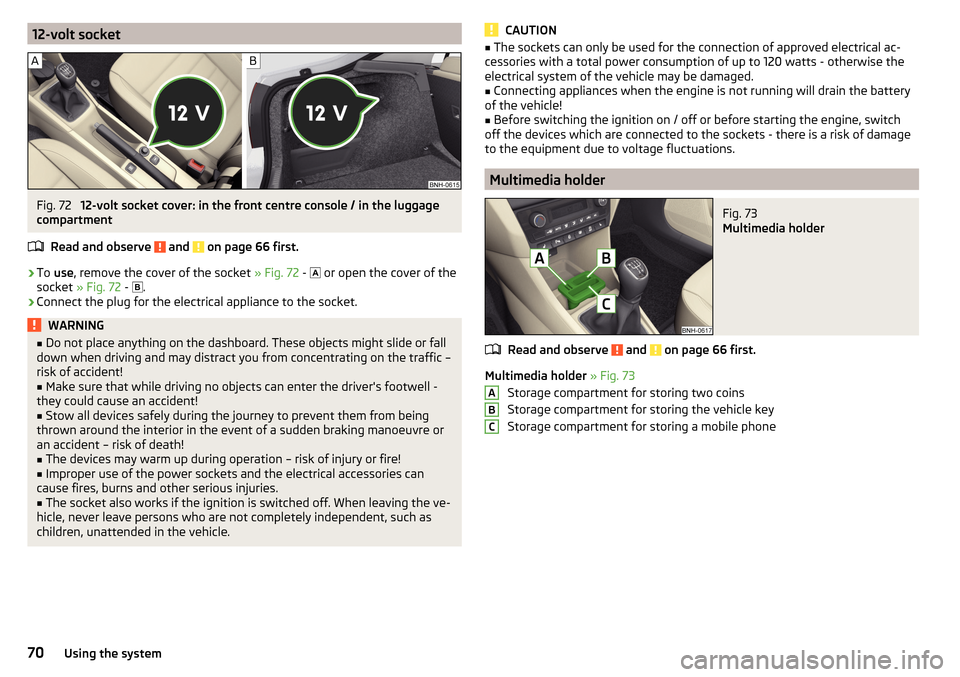
12-volt socketFig. 72
12-volt socket cover: in the front centre console / in the luggage
compartment
Read and observe
and on page 66 first.
›
To use , remove the cover of the socket » Fig. 72 -
or open the cover of the
socket » Fig. 72 -
.
›
Connect the plug for the electrical appliance to the socket.
WARNING■
Do not place anything on the dashboard. These objects might slide or fall
down when driving and may distract you from concentrating on the traffic –
risk of accident!■
Make sure that while driving no objects can enter the driver's footwell -
they could cause an accident!
■
Stow all devices safely during the journey to prevent them from being
thrown around the interior in the event of a sudden braking manoeuvre or
an accident – risk of death!
■
The devices may warm up during operation – risk of injury or fire!
■
Improper use of the power sockets and the electrical accessories can
cause fires, burns and other serious injuries.
■
The socket also works if the ignition is switched off. When leaving the ve-
hicle, never leave persons who are not completely independent, such as
children, unattended in the vehicle.
CAUTION■ The sockets can only be used for the connection of approved electrical ac-
cessories with a total power consumption of up to 120 watts - otherwise the
electrical system of the vehicle may be damaged.■
Connecting appliances when the engine is not running will drain the battery
of the vehicle!
■
Before switching the ignition on / off or before starting the engine, switch
off the devices which are connected to the sockets - there is a risk of damage
to the equipment due to voltage fluctuations.
Multimedia holder
Fig. 73
Multimedia holder
Read and observe and on page 66 first.
Multimedia holder » Fig. 73
Storage compartment for storing two coins
Storage compartment for storing the vehicle key
Storage compartment for storing a mobile phone
ABC70Using the system
Page 78 of 184
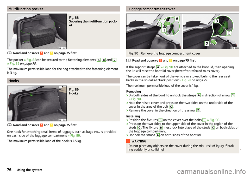
Multifunction pocketFig. 88
Securing the multifunction pock-
et
Read and observe and on page 75 first.
The pocket » Fig. 88can be secured to the fastening elements
A
,
B
and
C
» Fig. 85 on page 75 .
The maximum permissible load for the bag attached to the fastening element
is 3 kg.
Hooks
Fig. 89
Hooks
Read and observe and on page 75 first.
One hook for attaching small items of luggage, such as bags etc., is provided
on each side of the luggage compartment » Fig. 89.
The maximum permissible load of the hook is 7.5 kg.
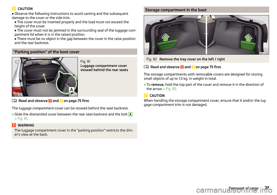
Luggage compartment coverFig. 90
Remove the luggage compartment cover
Read and observe
and on page 75 first.
If the support straps
A
» Fig. 90 are attached to the boot lid, then opening
the lid will raise the boot lid cover (hereafter referred to as cover).
The cover can be taken out of the vehicle or stowed behind the rear seat
backs in the so-called “Park position” » Fig. 91 on page 77 .
The maximum permissible load of the cover is 1 kg.
Removing
›
On both sides of the boot lid unhook the straps
A
in direction of arrow
1
» Fig. 90 .
›
Hold the raised cover and press on the two sides on the underside of the
cover in the area of the bolt
C
.
›
Remove the cover in the direction of the arrow
2
.
Installing
›
Position the fixtures
B
on the cover over the bolts
C
» Fig. 90 .
›
Press on the two sides to the upper side of the cover in the region of the
studs
C
. The fixture
B
must lock into place of the studs
C
on both sides of
the luggage compartment.
›
Unhook the straps
A
on both sides of the boot lid.
WARNINGDo not place any objects on the cover during the trip - risk of injury if brak-
ing suddenly or colliding! 76Using the system
Page 79 of 184
CAUTION■Observe the following instructions to avoid canting and the subsequent
damage to the cover or the side trim. ■ The cover must be inserted properly and the load must not exceed the
height of the cover.
■ The cover must not be jammed in the surrounding seal of the luggage com-
partment lid when it is in the raised position. ■ There must be no object in the gap between the cover in the raise position
and the rear backrest.
“Parking position” of the boot cover
Fig. 91
Luggage compartment cover
stowed behind the rear seats
Read and observe and on page 75 first.
The luggage compartment cover can be stowed behind the seat backrest.
›
Slide the dismantled cover between the rear seat backrest and the bolt
A
» Fig. 91 .
WARNINGThe luggage compartment cover in the “parking position” restricts the driv-
er's view at the back.Storage compartment in the bootFig. 92
Remove the tray cover on the left / right
Read and observe
and on page 75 first.
The storage compartments with removable covers are designed for storing
small objects of up to 1.5 kg. in weight in total.
›
To remove , hold the top part of the cover and remove it in the direction of
the arrow » Fig. 92.
CAUTION
When handling the storage compartment cover, ensure that it and/or the lug-
gage compartment trim is not damaged.77Transport of cargo
Page 92 of 184
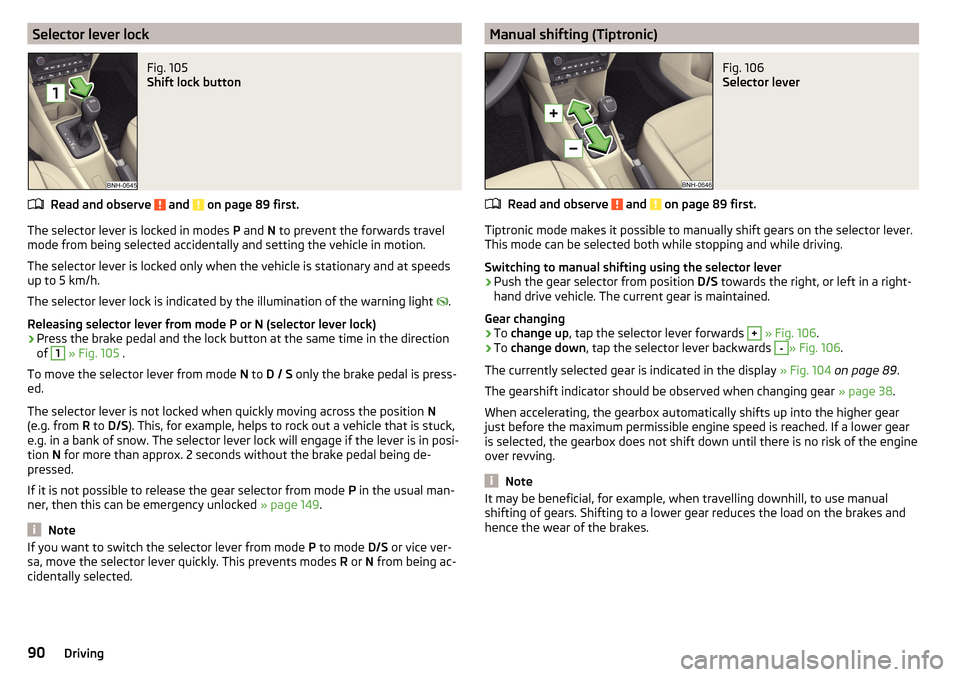
Selector lever lockFig. 105
Shift lock button
Read and observe and on page 89 first.
The selector lever is locked in modes P and N to prevent the forwards travel
mode from being selected accidentally and setting the vehicle in motion.
The selector lever is locked only when the vehicle is stationary and at speeds
up to 5 km/h.
The selector lever lock is indicated by the illumination of the warning light .
Releasing selector lever from mode P or N (selector lever lock)
›
Press the brake pedal and the lock button at the same time in the direction
of
1
» Fig. 105 .
To move the selector lever from mode N to D / S only the brake pedal is press-
ed.
The selector lever is not locked when quickly moving across the position N
(e.g. from R to D/S ). This, for example, helps to rock out a vehicle that is stuck,
e.g. in a bank of snow. The selector lever lock will engage if the lever is in posi-
tion N for more than approx. 2 seconds without the brake pedal being de-
pressed.
If it is not possible to release the gear selector from mode P in the usual man-
ner, then this can be emergency unlocked » page 149.
Note
If you want to switch the selector lever from mode P to mode D/S or vice ver-
sa, move the selector lever quickly. This prevents modes R or N from being ac-
cidentally selected.Manual shifting (Tiptronic)Fig. 106
Selector lever
Read and observe and on page 89 first.
Tiptronic mode makes it possible to manually shift gears on the selector lever.
This mode can be selected both while stopping and while driving.
Switching to manual shifting using the selector lever
›
Push the gear selector from position D/S towards the right, or left in a right-
hand drive vehicle. The current gear is maintained.
Gear changing
›
To change up , tap the selector lever forwards
+
» Fig. 106 .
›
To change down , tap the selector lever backwards
-
» Fig. 106.
The currently selected gear is indicated in the display » Fig. 104 on page 89 .
The gearshift indicator should be observed when changing gear » page 38.
When accelerating, the gearbox automatically shifts up into the higher gear
just before the maximum permissible engine speed is reached. If a lower gear
is selected, the gearbox does not shift down until there is no risk of the engine
over revving.
Note
It may be beneficial, for example, when travelling downhill, to use manual
shifting of gears. Shifting to a lower gear reduces the load on the brakes and
hence the wear of the brakes.90Driving
Page 97 of 184
Electronic Differential Lock (EDL)Read and observe
on page 94 first.
EDL prevents the turning of the respective wheel of the driven axle. EDL
brakes a spinning wheel if required and transfers the drive power force to the
other drive wheel. Driving becomes easier on road surfaces with different trac-
tion under each wheel of the driven axle.
The EDL switches off automatically in order to avoid excessive heat generation
on the brake of the wheel being braked. Once the brakes have cooled down,
there is an automatic re-activation of EDL.
Brake Assist (HBA)
Read and observe
on page 94 first.
The HBA increases the braking effect and helps to reduce the braking dis-
tance.
The HBA is activated by the very quick operation of the brake pedal. In order to
achieve the shortest possible braking distance, the brake pedal must be ap-
plied firmly until the vehicle has come to a standstill.
The HBA function is automatically deactivated when the brake pedal is re-
leased.
Hill Start Assist (HHC)
Read and observe
on page 94 first.
When moving off on a gradient, HHC allows you to move your foot from the
brake pedal to the accelerator pedal without the vehicle rolling downhill.
The vehicle is braked by the system for about 2 seconds after releasing the
brake pedal.
The HHC is active on gradients upwards up 5 % if the driver door is closed. HHC
is only ever active on slopes when in forward or reverse start off.
Multi collision brake (MCB)
Read and observe
on page 94 first.
MCB helps to decrease speed after a collision by means of automatic braking
interventions and to stabilise the vehicle. This reduces the risk of a subse-
quent crash due to uncontrolled vehicle movement.
The automatic brake interventions can take place only if the following condi-
tions are met.
There was a front, side and rear-end collision of a certain severity.
The impact speed was greater than approx. 10 km/h.
The brakes, the ESL and other required electrical systems remain function-
al after impact.
The accelerator pedal is not actuated.
Trailer stabilization system (TSA)
Read and observe
on page 94 first.
The TSA helps the combination stable in situations where the trailer sways
and then the whole trailer combination.
TSA brakes the individual wheels of the towing vehicle in order to damp the
rocking motion of the entire vehicle combination.
The following conditions are required for the correct TSA function. The trailer was shipped from the factory or purchased from the ŠKODA
genuine accessories.
The trailer is electrically connected to the towing vehicle by means of the
trailer socket.
The TCS is activated.
The speed is greater than 60 km/h.
Further information » page 108, Towing device and trailer .
95Assist systems