key SKODA RAPID SPACEBACK 2014 1.G User Guide
[x] Cancel search | Manufacturer: SKODA, Model Year: 2014, Model line: RAPID SPACEBACK, Model: SKODA RAPID SPACEBACK 2014 1.GPages: 204, PDF Size: 27.11 MB
Page 55 of 204
Switch-on display
The warning light flashes for around 2 seconds in quick succession, afterwards
it begins to flash evenly at longer intervals.WARNINGIf the car is locked and the safe securing system activated, no people must
remain in the car as it will then not be possible to either unlock a door or
open a window from the inside. The locked doors make it more difficult for
rescuers to get into the vehicle in an emergency – risk to life!
Individual settings
Read and observe
and on page 50 first.
Opening a single door
The function allows you to unlock only the driver's door and the fuel filler flap. The other doors and the boot lid remain locked and are only unlocked after be-
ing opened again.
Automatic locking/unlocking
All doors are locked from a speed of around 15 km/h. The button in the handle
of the boot lid is deactivated.
If the ignition key is withdrawn, the car is then automatically unlocked again. It
is also possible to unlock the vehicle by pressing the central locking button .
Note
■
Individual settings can be carried out in a specialist workshop.■For some countries with right-hand steering the function of the single door
opening is set at the factory.
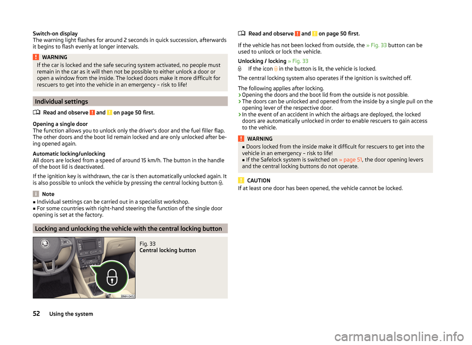
Locking and unlocking the vehicle with the central locking button
Fig. 33
Central locking button
Read and observe and on page 50 first.
If the vehicle has not been locked from outside, the » Fig. 33 button can be
used to unlock or lock the vehicle.
Unlocking / locking » Fig. 33
If the icon
in the button is lit, the vehicle is locked.
The central locking system also operates if the ignition is switched off.
The following applies after locking.
› Opening the doors and the boot lid from the outside is not possible.
› The doors can be unlocked and opened from the inside by a single pull on the
opening lever of the respective door.
› In the event of an accident in which the airbags are deployed, the locked
doors are automatically unlocked in order to enable rescuers to gain access
to the vehicle.
WARNING■ Doors locked from the inside make it difficult for rescuers to get into the
vehicle in an emergency – risk to life!■
If the Safelock system is switched on » page 51, the door opening levers
and the central locking buttons do not operate.
CAUTION
If at least one door has been opened, the vehicle cannot be locked.52Using the system
Page 56 of 204
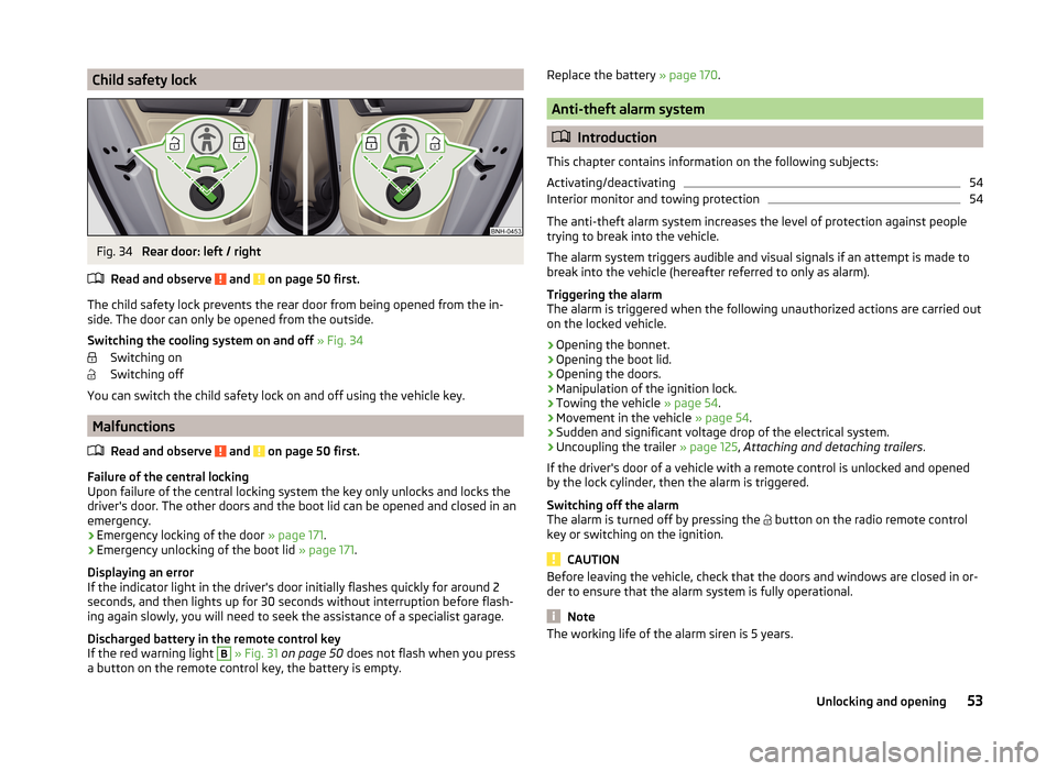
Child safety lockFig. 34
Rear door: left / right
Read and observe
and on page 50 first.
The child safety lock prevents the rear door from being opened from the in- side. The door can only be opened from the outside.
Switching the cooling system on and off » Fig. 34
Switching on
Switching off
You can switch the child safety lock on and off using the vehicle key.
Malfunctions
Read and observe
and on page 50 first.
Failure of the central locking
Upon failure of the central locking system the key only unlocks and locks the
driver's door. The other doors and the boot lid can be opened and closed in an
emergency.
› Emergency locking of the door
» page 171.
› Emergency unlocking of the boot lid
» page 171.
Displaying an error
If the indicator light in the driver's door initially flashes quickly for around 2
seconds, and then lights up for 30 seconds without interruption before flash-
ing again slowly, you will need to seek the assistance of a specialist garage.
Discharged battery in the remote control key
If the red warning light
B
» Fig. 31 on page 50 does not flash when you press
a button on the remote control key, the battery is empty.
Replace the battery » page 170.
Anti-theft alarm system
Introduction
This chapter contains information on the following subjects:
Activating/deactivating
54
Interior monitor and towing protection
54
The anti-theft alarm system increases the level of protection against people
trying to break into the vehicle.
The alarm system triggers audible and visual signals if an attempt is made to
break into the vehicle (hereafter referred to only as alarm).
Triggering the alarm
The alarm is triggered when the following unauthorized actions are carried out
on the locked vehicle.
› Opening the bonnet.
› Opening the boot lid.
› Opening the doors.
› Manipulation of the ignition lock.
› Towing the vehicle
» page 54.
› Movement in the vehicle
» page 54.
› Sudden and significant voltage drop of the electrical system.
› Uncoupling the trailer
» page 125, Attaching and detaching trailers .
If the driver's door of a vehicle with a remote control is unlocked and opened
by the lock cylinder, then the alarm is triggered.
Switching off the alarm
The alarm is turned off by pressing the button on the radio remote control
key or switching on the ignition.
CAUTION
Before leaving the vehicle, check that the doors and windows are closed in or-
der to ensure that the alarm system is fully operational.
Note
The working life of the alarm siren is 5 years.53Unlocking and opening
Page 58 of 204
NoteThe function of the button in the grip above the licence plate is deactivated
when starting off or at a speed of 5 km/hour or more for vehicles with central
locking. The function is restored after the vehicle stops and the door is
opened.
Opening/closing
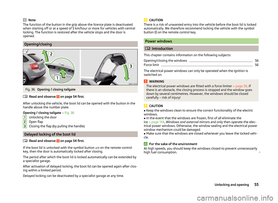
Fig. 36
Opening / closing tailgate
Read and observe
on page 54 first.
After unlocking the vehicle, the boot lid can be opened with the button in the
handle above the number plate.
Opening / closing tailgate » Fig. 36
Unlocking the door
Open flap
Closing the flap (by pulling the handle)
Delayed locking of the boot lid
Read and observe
on page 54 first.
If the boot lid is unlocked with the symbol button
on the remote control
key, then the door is automatically locked after closing.
The period after which the boot lid is locked automatically can be extended by a specialist garage.
After activation of delayed locking, the boot lid can be opened again after clos-
ing within a limited period.
Delayed locking can be deactivated by a specialist garage at any time.
123CAUTIONThere is a risk of unwanted entry into the vehicle before the boot lid is locked
automatically. We therefore recommend locking the vehicle with the symbol
button
on the remote control key.
Power windows
Introduction
This chapter contains information on the following subjects:
Opening/closing the windows
56
Force limit
56
The electrical power windows can only be operated when the ignition is
switched on.
WARNINGThe electrical power windows are fitted with a force limiter » page 56. If
there is an obstacle, the closing process is stopped and the window goes
down by several centimetres. However, the windows should be closed
carefully – risk of injury!
CAUTION
■ Keep the windows clean to ensure the correct functionality of the electric
windows.■
In the event that the windows are frozen, first of all eliminate the
ice » page 134 , Windows and external mirrors and only then operate the elec-
trical power windows. Otherwise, the window sealing and the electrical power
window mechanism could be damaged.
■
Make sure that the windows are closed whenever you leave the locked vehi-
cle.
For the sake of the environment
At high speeds, you should keep the windows closed to prevent unnecessarily high fuel consumption. 55Unlocking and opening
Page 62 of 204
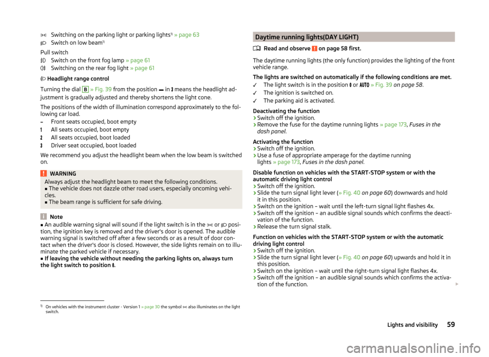
Switching on the parking light or parking lights1)
» page 63
Switch on low beam 1)
Pull switch Switch on the front fog lamp » page 61
Switching on the rear fog light » page 61
Headlight range control
Turning the dial B
» Fig. 39 from the position
in
means the headlight ad-
justment is gradually adjusted and thereby shortens the light cone.
The positions of the width of illumination correspond approximately to the fol- lowing car load.
Front seats occupied, boot empty
All seats occupied, boot empty
All seats occupied, boot loaded
Driver seat occupied, boot loaded
We recommend you adjust the headlight beam when the low beam is switched
on.
WARNINGAlways adjust the headlight beam to meet the following conditions.■The vehicle does not dazzle other road users, especially oncoming vehi-
cles.■
The beam range is sufficient for safe driving.
Note
■ An audible warning signal will sound if the light switch is in the or posi-
tion, the ignition key is removed and the driver's door is opened. The audible
warning signal is switched off after a few seconds or as a result of door con-
tact when the driver's door is closed. However, the side lights remain on to illu-
minate the parked vehicle if necessary.■
If leaving the vehicle without needing the parking lights on, always turn
the light switch to position
.
Daytime running lights(DAY LIGHT)
Read and observe
on page 58 first.
The daytime running lights (the only function) provides the lighting of the frontvehicle range.
The lights are switched on automatically if the following conditions are met. The light switch is in the position
or
» Fig. 39 on page 58 .
The ignition is switched on.
The parking aid is activated.
Deactivating the function
›
Switch off the ignition.
›
Remove the fuse for the daytime running lights » page 173, Fuses in the
dash panel .
Activating the function
›
Switch off the ignition.
›
Use a fuse of appropriate amperage for the daytime running
lights » page 173 , Fuses in the dash panel .
Disable function on vehicles with the START-STOP system or with the
automatic driving light control
›
Switch off the ignition.
›
Slide the turn signal light lever ( » Fig. 40 on page 60 ) downwards and hold
it in this position.
›
Switch on the ignition – wait until the left-turn signal light flashes 4x.
›
Switch off the ignition – an audible signal sounds which confirms the deacti-
vation of the function.
›
Release the turn signal stalk.
Function on vehicles with the START-STOP system or with the automatic
driving light control
›
Switch off the ignition.
›
Slide the turn signal light lever ( » Fig. 40 on page 60 ) upwards and hold it in
this position.
›
Switch on the ignition – wait until the right-turn signal light flashes 4x.
›
Switch off the ignition – an audible signal sounds which confirms the activa-
tion of the function.
1)
On vehicles with the instrument cluster - Version 1
» page 30 the symbol also illuminates on the light
switch.
59Lights and visibility
Page 66 of 204
Parking lightRead and observe
on page 58 first.
The parking light is provided for a temporary lighting of the parked vehicle.
Parking light
switching on
›
Switch off the ignition.
›
Place the control lever into position
A
or
B
as far as it can go » Fig. 40 on
page 60 - the parking light on the right/left-hand side of the vehicle is
switched on.
If the right or left turn signal light has been switched on and the ignition is
switched off, the parking light is not automatically switched on.
Switching on the side light on both sides
›
Turn the light switch
A
to position
» Fig. 39 on page 58 and lock the ve-
hicle.
After pulling out the ignition key and opening the driver's door, an audible
warning sounds. After a few seconds or after closing the driver's door, the au-
dible alarm is turned off, but the parking lights will remain switched on.
On vehicles with an instrument cluster -version 1 » page 30 the light switch
symbol also illuminates when the two-sided parking light is switched on.
CAUTION
Turning on the parking light means the battery is heavily loaded, especially
over short distances.
Driving abroad
Read and observe
on page 58 first.
The low beam is set asymmetrically. It illuminates the side of the road on
which the vehicle is being driven to a greater extent.
When driving in countries with opposing traffic system (traffic on the left/
right), asymmetric headlight adjustment can dazzle oncoming traffic. In order
to avoid this, the headlights must be adjusted at a specialist garage.
Note
You can find out more information on adjusting the headlights at a specialist
garage.Interior lighting
Introduction
This chapter contains information on the following subjects:
Front interior light
63
Rear interior light
64
Note
With the ignition off, the light turns off automatically after about 10 minutes.
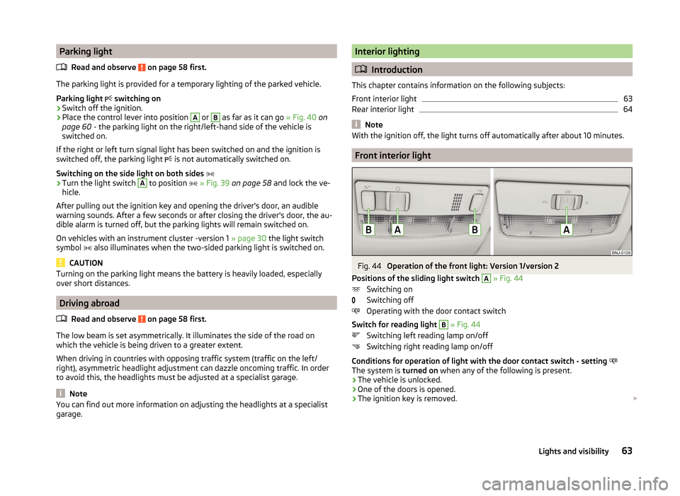
Front interior light
Fig. 44
Operation of the front light: Version 1/version 2
Positions of the sliding light switch
A
» Fig. 44
Switching on
Switching off
Operating with the door contact switch
Switch for reading light
B
» Fig. 44
Switching left reading lamp on/off
Switching right reading lamp on/off
Conditions for operation of light with the door contact switch - setting
The system is turned on when any of the following is present.
› The vehicle is unlocked.
› One of the doors is opened.
› The ignition key is removed.
63Lights and visibility
Page 93 of 204
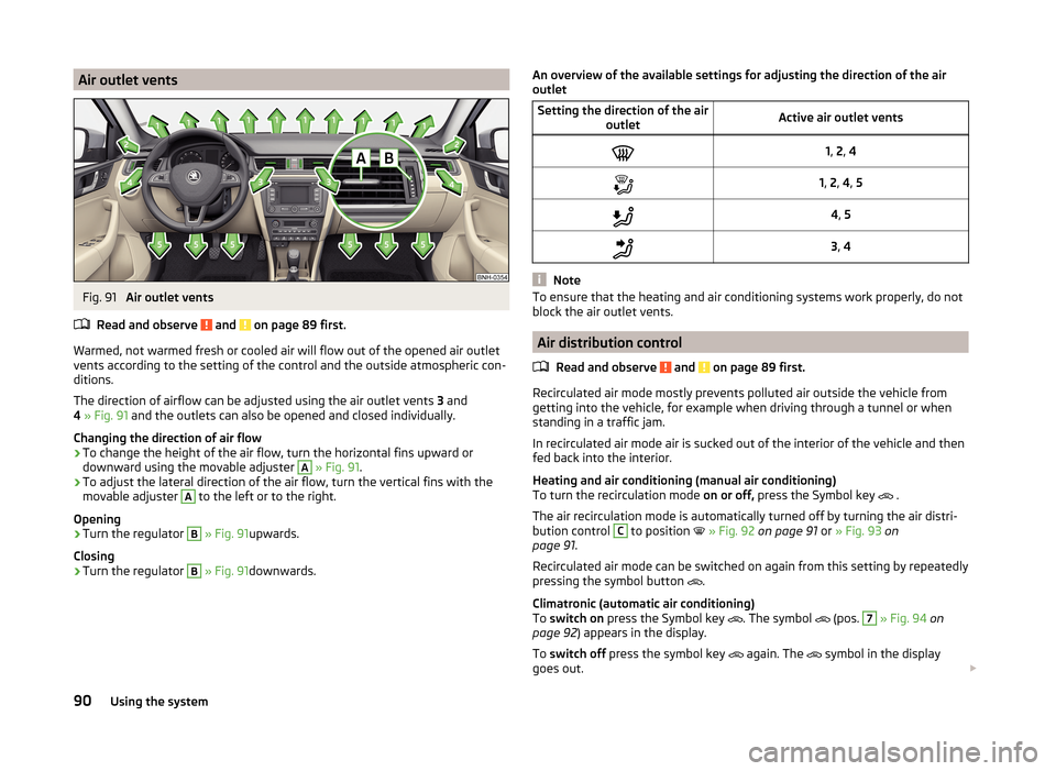
Air outlet ventsFig. 91
Air outlet vents
Read and observe
and on page 89 first.
Warmed, not warmed fresh or cooled air will flow out of the opened air outlet
vents according to the setting of the control and the outside atmospheric con-
ditions.
The direction of airflow can be adjusted using the air outlet vents 3 and
4 » Fig. 91 and the outlets can also be opened and closed individually.
Changing the direction of air flow
›
To change the height of the air flow, turn the horizontal fins upward or
downward using the movable adjuster
A
» Fig. 91 .
›
To adjust the lateral direction of the air flow, turn the vertical fins with the
movable adjuster
A
to the left or to the right.
Opening
›
Turn the regulator
B
» Fig. 91 upwards.
Closing
›
Turn the regulator
B
» Fig. 91 downwards.
An overview of the available settings for adjusting the direction of the air
outletSetting the direction of the air outletActive air outlet vents1, 2 , 41, 2 , 4 , 54 , 53 , 4
Note
To ensure that the heating and air conditioning systems work properly, do not
block the air outlet vents.
Air distribution control
Read and observe
and on page 89 first.
Recirculated air mode mostly prevents polluted air outside the vehicle from
getting into the vehicle, for example when driving through a tunnel or when
standing in a traffic jam.
In recirculated air mode air is sucked out of the interior of the vehicle and then
fed back into the interior.
Heating and air conditioning (manual air conditioning)
To turn the recirculation mode on or off, press the Symbol key
.
The air recirculation mode is automatically turned off by turning the air distri-
bution control
C
to position
» Fig. 92 on page 91 or » Fig. 93 on
page 91 .
Recirculated air mode can be switched on again from this setting by repeatedly
pressing the symbol button .
Climatronic (automatic air conditioning)
To switch on press the Symbol key
. The symbol
(pos.
7
» Fig. 94 on
page 92 ) appears in the display.
To switch off press the symbol key
again. The
symbol in the display
goes out.
90Using the system
Page 95 of 204
Setting the direction of the air outlet » page 90
›
Air flow to the windows
›
Air flow to the upper body
›
Air flow in the footwell
›
Airflow over the windows and into the footwell
Switch recirculation on/off » page 90
Switch the cooling system on/off
Note
■ The warning light in the button illuminates after activation, even if not all
of the conditions for the function of the cooling system have been met. By
lighting up of the warning light in the button, the operational readiness of the
cooling system is signalled.■
During operation of the air conditioning, an increase in engine idle speed may
occur under certain circumstances in order to ensure sufficient heating com-
fort.
Climatronic (automatic air conditioning)
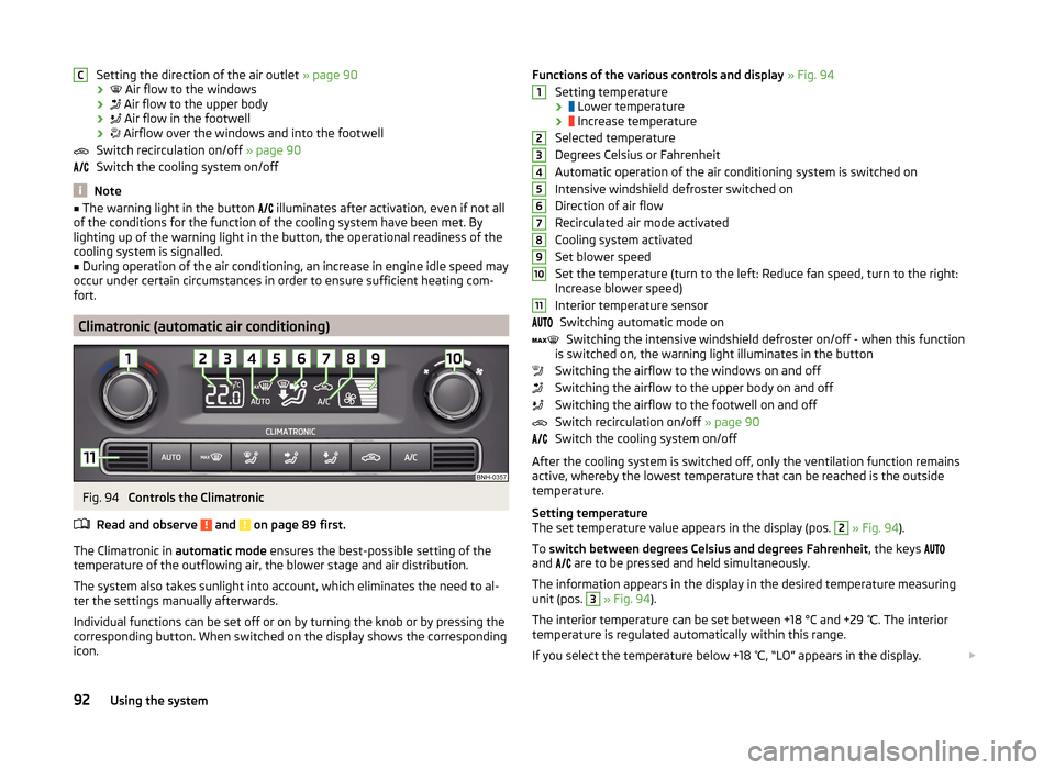
Fig. 94
Controls the Climatronic
Read and observe
and on page 89 first.
The Climatronic in automatic mode ensures the best-possible setting of the
temperature of the outflowing air, the blower stage and air distribution.
The system also takes sunlight into account, which eliminates the need to al-
ter the settings manually afterwards.
Individual functions can be set off or on by turning the knob or by pressing the
corresponding button. When switched on the display shows the corresponding
icon.
CFunctions of the various controls and display » Fig. 94
Setting temperature ›
Lower temperature
›
Increase temperature
Selected temperature
Degrees Celsius or Fahrenheit
Automatic operation of the air conditioning system is switched on
Intensive windshield defroster switched on
Direction of air flow
Recirculated air mode activated
Cooling system activated
Set blower speed
Set the temperature (turn to the left: Reduce fan speed, turn to the right:
Increase blower speed)
Interior temperature sensor Switching automatic mode on Switching the intensive windshield defroster on/off - when this function
is switched on, the warning light illuminates in the button
Switching the airflow to the windows on and off
Switching the airflow to the upper body on and off
Switching the airflow to the footwell on and off
Switch recirculation on/off » page 90
Switch the cooling system on/off
After the cooling system is switched off, only the ventilation function remains
active, whereby the lowest temperature that can be reached is the outside
temperature.
Setting temperature
The set temperature value appears in the display (pos. 2
» Fig. 94 ).
To switch between degrees Celsius and degrees Fahrenheit , the keys
and are to be pressed and held simultaneously.
The information appears in the display in the desired temperature measuring
unit (pos.
3
» Fig. 94 ).
The interior temperature can be set between +18 °C and +29 ℃. The interior
temperature is regulated automatically within this range.
If you select the temperature below +18 ℃, “LO” appears in the display.
123456789101192Using the system
Page 100 of 204
›If the hands-free system announces (as standard
SKODA_BT) on the display
of the mobile phone, enter the PIN 1)
within 30 seconds and wait, until the
connection is established 2)
.›
To finish pairing in the MAXI DOT display, confirm the creation of the new
user profile.
If there is no free space available to create a new user profile, delete an exist- ing user profile.
During the connecting procedure, no other mobile phone may be connected
with the hands-free system.
Up to four mobile phones can be paired with the hands-free system, whereby
only one mobile phone can communicate with the hands-free system.
The visibility of the hands-free system is automatically switched off 3 minutes
after the ignition is switched on and is also deactivated when the mobile
phone has connected to the hands-free system.
Restoring the visibility of the hands-free system
If you have not managed to connect your mobile phone with the hands-free
system within 3 minutes of switching on the ignition, the visibility of the
hands-free system can be re-established for 3 minutes in one of the following
ways.
› By turning the ignition off and on.
› By turning voice control off and on.
› In the MAXI DOT display under menu item
Bluetooth - Visibility .
Creating a connection with an already paired mobile phone
After switching on the ignition, the connection is automatically established for
the already paired mobile phone 2)
. Check on your mobile phone if the automatic
connection has been established.
Disconnecting the connection
The connection to a connected mobile phone can be ended in the following
ways.
› By withdrawing the ignition key.
› By disconnecting the hands-free system in the mobile phone.
› By disconnecting from the user in the MAXI DOT display under the menu item
Bluetooth - User .
Solving connection problems
If the hands-free system reports No paired phone found, check the operating
status of the mobile phone.
› Is the mobile phone switched on?
› Is the PIN code entered?
› Is Bluetooth ®
active?
› Is the visibility of the mobile phone active?
› Has the mobile phone already been paired with the hands-free system?
Telephone operation in the MAXI DOT display
Read and observe
on page 94 first.
The following menu items can be selected from the Phone menu.
› Phone book
› Dial number 3)
› Call register
› Voice mailbox
› Bluetooth 3)
› Settings 4)
› Back
Phone book
The Phone book menu item lists the contacts downloaded from the telephone
memory and the mobile phone SIM card.
1)
Depending on the Bluetooth®
version on the mobile phone, an automatically generated 6-digit PIN (SSP)
is either displayed, or the PIN 1234 has to be entered manually.
2)
Some mobile phones have a menu, in which the authorisation for establishing a Bluetooth ®
connection
is completed by inputting a PIN number. If the authorisation input is required, it must always be per-
formed when re-establishing the Bluetooth connection.
3)
On vehicles fitted with the Amundsen+ navigation system, this function can be accessed via the naviga-
tion system menu; refer to the » operating instructions for the Amundsen+ navigation system .
4)
This function is not available in vehicles fitted with the Amundsen+ navigation system.
97Communication and multimedia
Page 105 of 204

The ŠKODA applications installed in a connected communications device (e.g.
phone, tablet, notebook) 1)
offer the possibility to further process the received
data.
Available applications and further information can be found on the ŠKODA
website..WARNING■ The national legal regulations for using mobile communication devices in
a vehicle must be observed.■
Do not fit the equipment or mounts to be connected onto airbag covers
or within the immediate deployment range of the airbags.
■
Never leave a connected device in the deployment area of an airbag, on a
seat, on the dash panel or any another area, from which it can be thrown
during a sudden braking manoeuvre, an accident or a collision - there is a
risk of injury.
Note
The Wi-Fi range is limited to the interior of the vehicle.
Connection with SmartGate
Read and observe
on page 102 first.
For a successful connection the following conditions must be met. Wi-Fi is turned on in the device to be connected.
The ignition is switched on.
Connect
›
Can enable the connected device to search for available Wi-Fi networks (see
operating instructions for the connected device).
›
In the found networks menu, select the connection to the
“SmartGate_ ... ”network 2)
.
›
Enter the password (the password is pre-set at the factory to the complete
Vehicle Identification Number - enter capital letters).
Disconnecting the connection
The connection to SmartGate can be ended in the following ways.
› By disconnecting the connected device from SmartGate.›By turning off the Wi-Fi in the connected device.›
By switching off the ignition and removing the key for more than 5 s (for ve-
hicles with starter button - by turning off the engine and opening the driver's
door).
Automatic connection
The connection to SmartGate is automatically restored under the following
conditions.
Wi-Fi is turned on in the device to be connected.
The ignition is switched on.
The device to be connected stores the password required for the connec-
tion check.
Connection problems
If the connection fails, check the following points.
› Are the conditions for a successful connection fulfilled?
› Is Smart Gate available in the list of available Wi-Fi networks?
› Has the password required for the connection check been entered?
› Is the password is required for the connection check correct?
› Is the device to be connected still connected to another Wi-Fi network?
If the above items are ok but the connection still fails, contact a ŠKODA part-
ner.
Note
Up to four devices can be connected to SmartGate at a time.
Smart Gate website
Read and observe
on page 102 first.
There is a special website for the SmartGate system.
The following address must be entered in the web browser of the connected device.
HTTP://192.168.123.1
1)
The applications support communication devices with the Android operating system version 4.0.x and
later and iOS 7.xx and higher.
2)
The last six symbols of the VIN vehicle identification number of your vehicle are displayed at position ....
102Using the system
Page 106 of 204

This website contains information about the vehicle, the Wi-Fi connection and
SmartGate.
In the Configuration area the Wi-Fi connection settings can be adjusted.
Save the setting changes
The setting changes are only applied after performing the following steps.
› The changes are saved by pressing the “Save” button.
› SmartGate is restarted by pressing the “Reboot ”button.
Password Management
Read and observe
on page 102 first.
Password management can be done in the connected device on the Smart-
Gate website » page 102, Smart Gate website .
The changes are applied after saving and restarting SmartGate » page 103,
Save the setting changes .
Change password
›
Enter a new password in the Configuration area in menu option WPA / WPA2 key.
The password must be 8-17 characters without diacritics or special characters
(for example, -, /, etc.).
Connection option without entering a password
›
In the Configuration area set the value Open in the menu item Security .
Forgot password
If you have forgotten your password, SmartGate must be reset to factory set-
tings in a specialized workshop.
103Communication and multimedia