key SKODA ROOMSTER 2012 1.G User Guide
[x] Cancel search | Manufacturer: SKODA, Model Year: 2012, Model line: ROOMSTER, Model: SKODA ROOMSTER 2012 1.GPages: 194, PDF Size: 4.8 MB
Page 33 of 194
›
Vehicle inclination » page 31
;
› Interior of the vehicle
» page 31;
› A drop in voltage of the on-board power supply;
› Socket of the factory-fitted towing device.
An alarm is immediately triggered if either of the two battery terminals is discon-
nected while the anti-theft alarm system is activated.
How is the alarm switched off?
The alarm is switched off by unlocking the vehicle with the radio remote control
or switching on the ignition. Note
■ The working life of the alarm siren is 5 years.
■ Before leaving the vehicle, check that all the doors and windows are closed in
order to ensure that the anti-theft alarm system is fully operational. ■ Coding of the radio remote control and the receiver unit precludes the use of
the radio remote control from other vehicles. ÐInterior monitor and towing protection
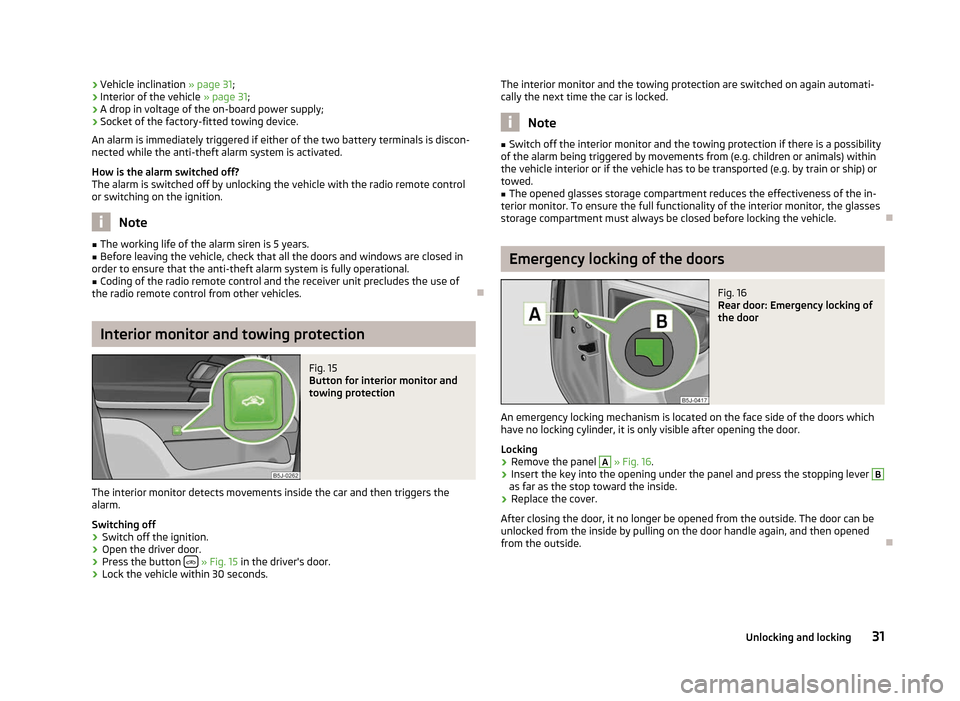
Fig. 15
Button for interior monitor and
towing protection
The interior monitor detects movements inside the car and then triggers the
alarm.
Switching off
› Switch off the ignition.
› Open the driver door.
› Press the button
» Fig. 15 in the driver's door.
› Lock the vehicle within 30 seconds. The interior monitor and the towing protection are switched on again automati-
cally the next time the car is locked. Note
■ Switch off the interior monitor and the towing protection if there is a possibility
of the alarm being triggered by movements from (e.g. children or animals) within
the vehicle interior or if the vehicle has to be transported (e.g. by train or ship) or
towed. ■ The opened glasses storage compartment reduces the effectiveness of the in-
terior monitor. To ensure the full functionality of the interior monitor, the glasses
storage compartment must always be closed before locking the vehicle. Ð Emergency locking of the doors
Fig. 16
Rear door: Emergency locking of
the door
An emergency locking mechanism is located on the face side of the doors which
have no locking cylinder, it is only visible after opening the door.
Locking › Remove the panel A
» Fig. 16
.
› Insert the key into the opening under the panel and press the stopping lever B
as far as the stop toward the inside.
› Replace the cover.
After closing the door, it no longer be opened from the outside. The door can be
unlocked from the inside by pulling on the door handle again, and then opened
from the outside. Ð
31
Unlocking and locking
Page 34 of 194
Boot lid
ä
Introduction
This chapter contains information on the following subjects:
Opening/closing 32
Automatic locking 32
Emergency unlocking 33
WARNING
■ Ensure that the lock is properly engaged after closing the boot lid. Other-
wise, the boot lid might open suddenly when driving even if the boot lid lock
was closed - risk of accident!
■ Never drive with the boot lid fully opened or slightly ajar otherwise exhaust
gases may get into the interior of the vehicle - risk of poisoning!
■ Do not press on the rear window when closing the boot lid, it could crack -
risk of injury! Note
■ After closing the boot lid, it is automatically locked within 1 second and the
anti-theft alarm system is activated. This applies only if the vehicle was locked
before closing the boot lid. ■ The function of the handle above the licence plate is deactivated when starting
off or at a speed of 5
km/hour or more for vehicles with central locking. The func-
tion of the handle is activated again when the vehicle has stopped and a door is
opened. Ð Opening/closing
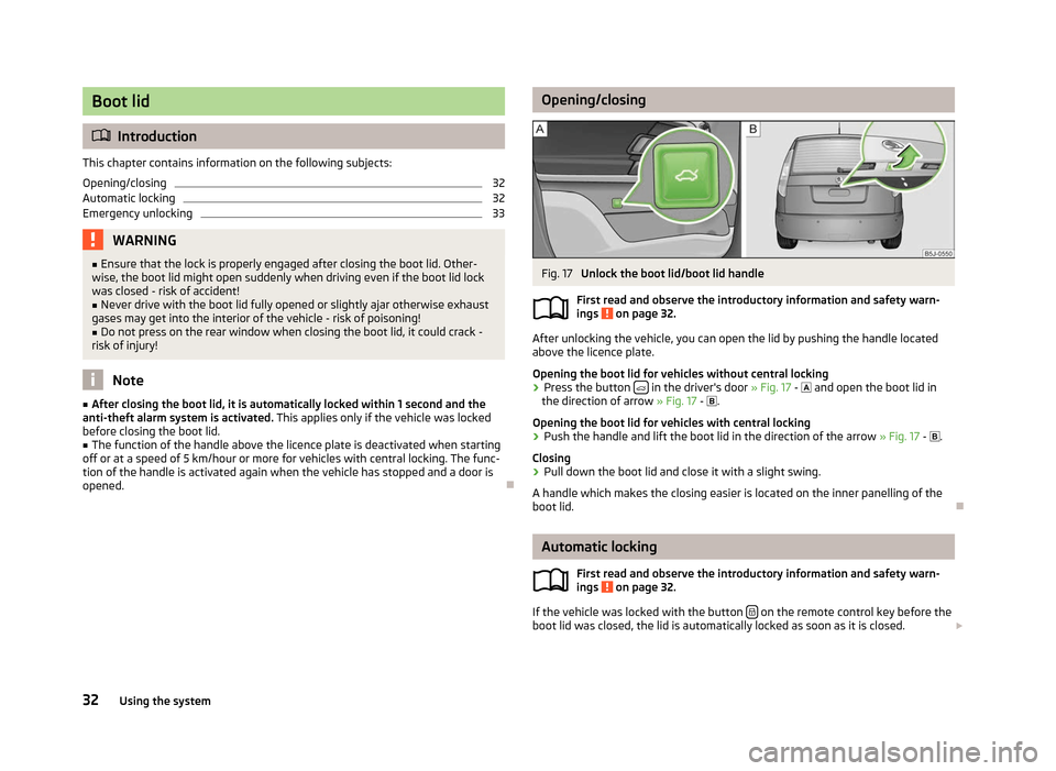
Fig. 17
Unlock the boot lid/boot lid handle
First read and observe the introductory information and safety warn-
ings on page 32.
After unlocking the vehicle, you can open the lid by pushing the handle located
above the licence plate.
Opening the boot lid for vehicles without central locking
›
Press the button
in the driver's door
» Fig. 17 - and open the boot lid in
the direction of arrow » Fig. 17 - .
Opening the boot lid for vehicles with central locking › Push the handle and lift the boot lid in the direction of the arrow
» Fig. 17 - .
Closing
› Pull down the boot lid and close it with a slight swing.
A handle which makes the closing easier is located on the inner panelling of the
boot lid. Ð Automatic locking
First read and observe the introductory information and safety warn-
ings on page 32.
If the vehicle was locked with the button
on the remote control key before the
boot lid was closed, the lid is automatically locked as soon as it is closed. £
ä
ä
32 Using the system
Page 35 of 194
The delayed automatic locking function of the boot lid can be activated on your
vehicle. The following applies following activation of this function: If the boot lid
was locked with the button
on the remote control key 2
» page 29, then it is
possible to open the lid within a limited period of it being closed.
If you wish, a
ŠKODA Service Partner can activate or deactivate the delayed auto-
matic locking of the boot lid. The Service Partner will also provide any further in-
formation that is required.
There is a risk of unwanted entry into the vehicle before the boot lid is locked au-
tomatically. Always lock the vehicle using the button on the remote control or
with the key if no remote control is available » page 28 .ÐEmergency unlocking
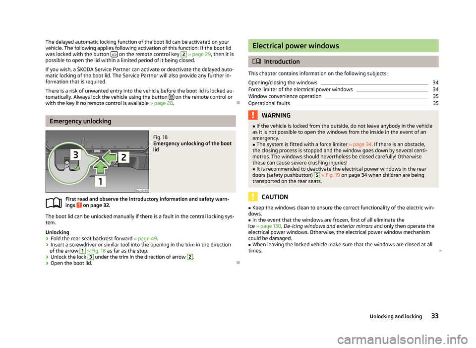
Fig. 18
Emergency unlocking of the boot
lid
First read and observe the introductory information and safety warn-
ings on page 32.
The boot lid can be unlocked manually if there is a fault in the central locking sys-
tem.
Unlocking
›
Fold the rear seat backrest forward
» page 49.
› Insert a screwdriver or similar tool into the opening in the trim in the direction
of the arrow 1
» Fig. 18 as far as the stop.
› Unlock the lock 3
under the trim in the direction of arrow 2
.
› Open the boot lid. Ð
ä Electrical power windows
ä
Introduction
This chapter contains information on the following subjects:
Opening/closing the windows 34
Force limiter of the electrical power windows 34
Window convenience operation 35
Operational faults 35
WARNING
■ If the vehicle is locked from the outside, do not leave anybody in the vehicle
as it is not possible to open the windows from the inside in the event of an
emergency.
■ The system is fitted with a force limiter » page 34. If there is an obstacle,
the closing process is stopped and the window goes down by several centi-
metres. The windows should nevertheless be closed carefully! Otherwise
these can cause severe crushing injuries!
■ It is recommended to deactivate the electrical power windows in the rear
doors (safety pushbutton) S
» Fig. 19 on page 34 when children are being
transported on the rear seats. CAUTION
■ Keep the windows clean to ensure the correct functionality of the electric win-
dows. ■ In the event that the windows are frozen, first of all eliminate the
ice » page 130, De-icing windows and exterior mirrors and only then operate the
electrical power windows. Otherwise, the electrical power window mechanism
could be damaged. ■ When leaving the locked vehicle make sure that the windows are closed at all
times. £
33
Unlocking and locking
Page 37 of 194
If you attempt to close the window again within 10 seconds of the window being
moved down for the second time, even though the obstacle was not yet been re-
moved, the closing process is only stopped. During this time it is not possible to
automatically close the window. The force limiter is still switched on.
The force limiter is only switched off if you attempt to close the window again
within the next 10
seconds - the window will now close with full force!
If you wait longer than 10 seconds, the force limiter is switched on again. ÐWindow convenience operation
First read and observe the introductory information and safety warn-
ings on page 33.
The electrical power windows can be opened and closed as follows when unlock-
ing and locking the vehicle.
Opening
› Press and hold the unlock button
on the remote control key.
› Hold the key in the driver's lock in the unlock position.
Closing
› Press and hold the lock button
on the remote control key.
› Hold the key in the driver's lock in the lock position.
You can interrupt the opening or closing process for the windows immediately by
releasing the key or the lock button. ÐOperational faults
First read and observe the introductory information and safety warn-
ings on page 33.
Electrical power windows do not operate
If the battery has been disconnected and then reconnected while the window
was opened, the electrical power windows will not operate. The system must be
activated. Proceed as follows in order to re-establish the function:
›
switch on the ignition;
› pull the top edge of the button in the driver's door to close the window;
› release the button;
› pull the relevant button upwards again for approx. 3
seconds.
ä
ä Operation in winter
In the winter, ice accumulating on the surface of the window may cause there to
be more resistance when closing the window. The window will stop and move
back several centimetres.
It is necessary to deactivate the force limiter to close the window » page 34.Ð Panorama roof
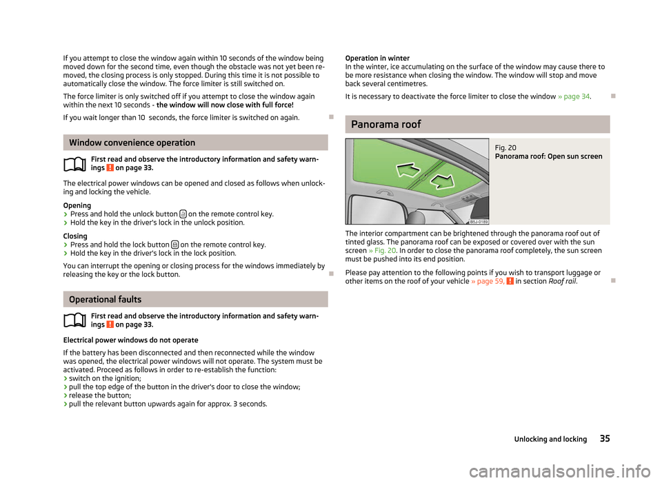
Fig. 20
Panorama roof: Open sun screen
The interior compartment can be brightened through the panorama roof out of
tinted glass. The panorama roof can be exposed or covered over with the sun
screen » Fig. 20. In order to close the panorama roof completely, the sun screen
must be pushed into its end position.
Please pay attention to the following points if you wish to transport luggage or
other items on the roof of your vehicle » page 59, in section Roof rail
.Ð 35
Unlocking and locking
Page 38 of 194
Lights and visibility
Lights
ä
Introduction
This chapter contains information on the following subjects:
Switching lights on and off 36
DAY LIGHT function (Daylight driving light) 37
Halogen projector headlights with cornering light function 37
Parking light 37
Tourist light 38
Fog lights 38
Fog lights with the function CORNER 38
Rear fog light 39
Headlight beam adjustment 39
Switches for the hazard warning light system 40
Turn signal and main beam lever 40
On models fitted with right-hand steering the position of certain switches differs
from that shown in » Fig. 21 on page
36. The symbols which mark the switch po-
sitions are identical, however. WARNING
Never drive with only the side lights on! The side lights are not bright enough
to light up the road sufficiently in front of you or to be seen by other oncom-
ing traffic. Therefore always switch on the low beam when it is dark or if visi-
bility is poor. CAUTION
■ The activation of the lights should only be undertaken in accordance with na-
tional legal requirements.
■ The driver is always responsible for the correct settings and use of the lights. Note
■ If the light switch is in the position , the ignition key is removed and the driv-
er's door is open, an audible warning signal will sound. The audible warning signal
is switched off by means of the door contact when the driver's door is closed (ig-
nition off), however, the side lights remain on to illuminate the parked vehicle if
necessary. ■ In the event of cool or humid weather conditions, the headlights can be misted
up from inside. The temperature difference between interior and external area of
the headlight lenses is decisive. When the driving lights are switched on, the light
outlet surfaces are free from mist after a short period, although the headlight
lenses may still be misted up in the peripheral areas. It also concerns reverse light
and turn signal lights. This mist has no influence on the life of the lighting system. Ð Switching lights on and off
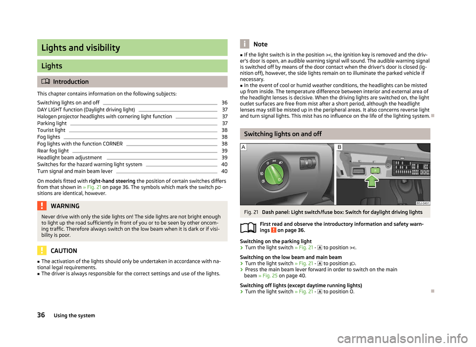
Fig. 21
Dash panel: Light switch/fuse box: Switch for daylight driving lights
First read and observe the introductory information and safety warn-
ings on page 36.
Switching on the parking light
› Turn the light switch
» Fig. 21 - to position .
Switching on the low beam and main beam
› Turn the light switch
» Fig. 21 - to position .
› Press the main beam lever forward in order to switch on the main
beam » Fig. 25 on page 40.
Switching off lights (except daytime running lights)
› Turn the light switch
» Fig. 21 - to position O. Ð
ä
36 Using the system
Page 43 of 194
Note
■ The turn signal system only operates when the ignition is switched on. The cor-
responding warning light or in the instrument cluster also flashes.
■ The turn signal is automatically cancelled after negotiating a curve.
■ The warning light flashes at twice its normal rate if a bulb for the turn signal
light fails. ÐInterior light
Interior lights at the front
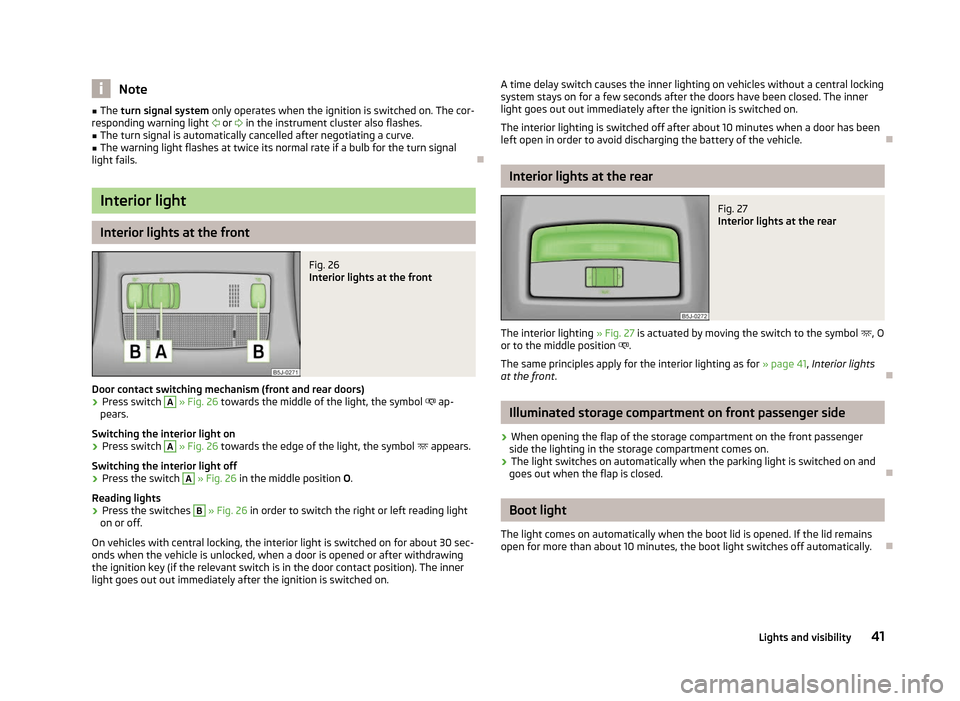
Fig. 26
Interior lights at the front
Door contact switching mechanism (front and rear doors) › Press switch A
» Fig. 26 towards the middle of the light, the symbol
ap-
pears.
Switching the interior light on
› Press switch A
» Fig. 26 towards the edge of the light, the symbol
appears.
Switching the interior light off
› Press the switch A
» Fig. 26
in the middle position O.
Reading lights
› Press the switches B
» Fig. 26
in order to switch the right or left reading light
on or off.
On vehicles with central locking, the interior light is switched on for about 30 sec-
onds when the vehicle is unlocked, when a door is opened or after withdrawing
the ignition key (if the relevant switch is in the door contact position). The inner
light goes out out immediately after the ignition is switched on. A time delay switch causes the inner lighting on vehicles without a central locking
system stays on for a few seconds after the doors have been closed. The inner
light goes out out immediately after the ignition is switched on.
The interior lighting is switched off after about 10 minutes when a door has been
left open in order to avoid discharging the battery of the vehicle. Ð Interior lights at the rear
Fig. 27
Interior lights at the rear
The interior lighting » Fig. 27 is actuated by moving the switch to the symbol , O
or to the middle position .
The same principles apply for the interior lighting as for » page 41, Interior lights
at the front . Ð Illuminated storage compartment on front passenger side
› When opening the flap of the storage compartment on the front passenger
side the lighting in the storage compartment comes on.
› The light switches on automatically when the parking light is switched on and
goes out when the flap is closed. Ð Boot light
The light comes on automatically when the boot lid is opened. If the lid remains
open for more than about 10
minutes, the boot light switches off automatically. Ð
41
Lights and visibility
Page 58 of 194
Removing/installing the carrier rails
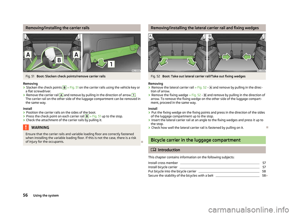
Fig. 51
Boot: Slacken check points/remove carrier rails
Removing
› Slacken the check points B
» Fig. 51
on the carrier rails using the vehicle key or
a flat screwdriver.
› Remove the carrier rail A
and remove by pulling in the direction of arrow 1
.
The carrier rail on the other side of the luggage compartment can be removed in
the same way.
Install
› Position the carrier rails on the sides of the boot.
› Press the check point on each carrier rail B
» Fig. 51
up to the stop.
› Check the attachment of the carrier rails by pulling it. WARNING
Ensure that the carrier rails and variable loading floor are correctly fastened
when installing the variable loading floor. If this is not the case, there is a risk
of injury for the occupants. Ð Removing/installing the lateral carrier rail and fixing wedges
Fig. 52
Boot: Take out lateral carrier rail/Take out fixing wedges
Removing
› Remove the lateral carrier rail
»
Fig. 52 - and remove by pulling in the direc-
tion of arrow.
› Remove the fixing wedge
» Fig. 52 - and remove by pulling in the direction of
arrow. To remove the fixing wedge on the other side of the luggage compart-
ment, proceed in the same way.
Install
› Put the fixing wedge on the fixing points and press in the direction of the sides
of the luggage compartment up to the stop.
› Insert the lateral carrier rail at an angle to the fixing wedges and press it up to
the stop.
› Check how well the lateral carrier rail is fastened by pulling on it. Ð Bicycle carrier in the luggage compartment
ä
Introduction
This chapter contains information on the following subjects:
Install cross member 57
Install bicycle carrier 57
Put bicycle into the bicycle carrier 58
Secure the stability of the bicycles with a belt 58
£
56 Using the system
Page 62 of 194
Ashtray
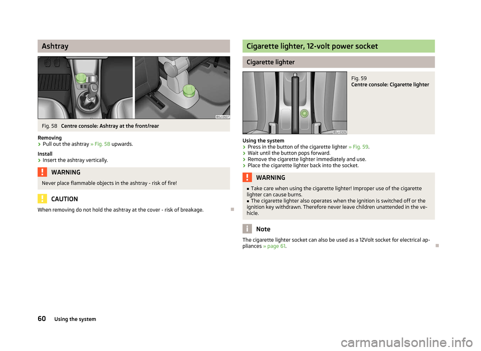
Fig. 58
Centre console: Ashtray at the front/rear
Removing › Pull out the ashtray
» Fig. 58 upwards.
Install
› Insert the ashtray vertically. WARNING
Never place flammable objects in the ashtray - risk of fire! CAUTION
When removing do not hold the ashtray at the cover - risk of breakage. Ð Cigarette lighter, 12-volt power socket
Cigarette lighter
Fig. 59
Centre console: Cigarette lighter
Using the system › Press in the button of the cigarette lighter
» Fig. 59.
› Wait until the button pops forward.
› Remove the cigarette lighter immediately and use.
› Place the cigarette lighter back into the socket. WARNING
■ Take care when using the cigarette lighter! Improper use of the cigarette
lighter can cause burns. ■ The cigarette lighter also operates when the ignition is switched off or the
ignition key withdrawn. Therefore never leave children unattended in the ve-
hicle. Note
The cigarette lighter socket can also be used as a 12Volt socket for electrical ap-
pliances » page 61. Ð
60 Using the system
Page 63 of 194
12-volt power socket
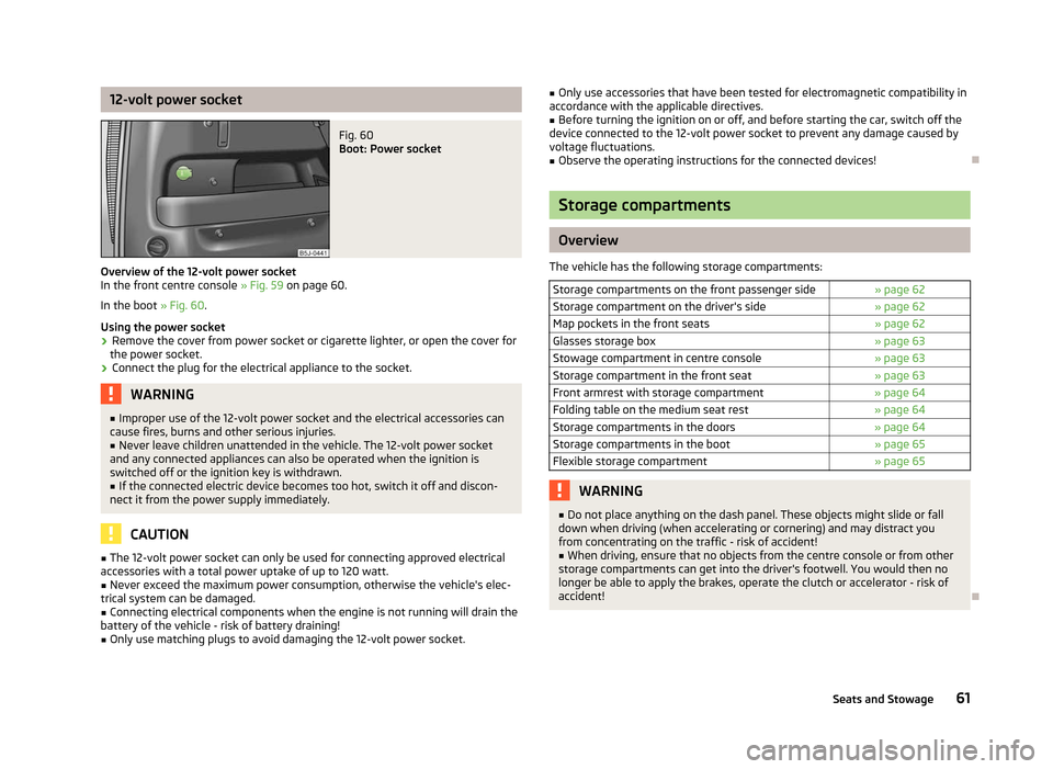
Fig. 60
Boot: Power socket
Overview of the 12-volt power socket
In the front centre console » Fig. 59 on page 60.
In the boot » Fig. 60.
Using the power socket
› Remove the cover from power socket or cigarette lighter, or open the cover for
the power socket.
› Connect the plug for the electrical appliance to the socket. WARNING
■ Improper use of the 12-volt power socket and the electrical accessories can
cause fires, burns and other serious injuries.
■ Never leave children unattended in the vehicle. The 12-volt power socket
and any connected appliances can also be operated when the ignition is
switched off or the ignition key is withdrawn.
■ If the connected electric device becomes too hot, switch it off and discon-
nect it from the power supply immediately. CAUTION
■ The 12-volt power socket can only be used for connecting approved electrical
accessories with a total power uptake of up to 120
watt.
■ Never exceed the maximum power consumption, otherwise the vehicle's elec-
trical system can be damaged.
■ Connecting electrical components when the engine is not running will drain the
battery of the vehicle - risk of battery draining! ■ Only use matching plugs to avoid damaging the 12-volt power socket. ■
Only use accessories that have been tested for electromagnetic compatibility in
accordance with the applicable directives.
■ Before turning the ignition on or off, and before starting the car, switch off the
device connected to the 12-volt power socket to prevent any damage caused by
voltage fluctuations.
■ Observe the operating instructions for the connected devices! Ð Storage compartments
Overview
The vehicle has the following storage compartments: Storage compartments on the front passenger side » page 62
Storage compartment on the driver's side » page 62
Map pockets in the front seats » page 62
Glasses storage box » page 63
Stowage compartment in centre console » page 63
Storage compartment in the front seat » page 63
Front armrest with storage compartment » page 64
Folding table on the medium seat rest » page 64
Storage compartments in the doors » page 64
Storage compartments in the boot » page 65
Flexible storage compartment » page 65 WARNING
■ Do not place anything on the dash panel. These objects might slide or fall
down when driving (when accelerating or cornering) and may distract you
from concentrating on the traffic - risk of accident!
■ When driving, ensure that no objects from the centre console or from other
storage compartments can get into the driver's footwell. You would then no
longer be able to apply the brakes, operate the clutch or accelerator - risk of
accident! Ð
61
Seats and Stowage
Page 78 of 194
Starting-off and Driving
Starting and stopping the engine
ä
Introduction
This chapter contains information on the following subjects:
Adjusting the steering wheel position 77
Electrohydraulic power steering 77
Electronic immobiliser 77
Ignition lock 78
Starting engine 78
Switching the engine off 78
WARNING
■ Never adjust the steering wheel when the vehicle is moving only when the
vehicle is stationary!
■ Maintain a distance of 25 cm 1
to the steering wheel
» Fig. 78 on page 77
- . Not maintaining this minimum distance will mean that the airbag system
will not be able to properly protect you - hazard!
■ The lever for adjusting the steering wheel must be locked whilst driving so
that the position of the steering wheel cannot accidently change during the
journey - risk of accident!
■ If the steering wheel is adjusted further towards the head, the protection
provided by the driver airbag in the event of an accident is reduced. Check
that the steering wheel is aligned to the chest. ■ When driving, hold the steering wheel with both hands firmly on the outer
edge in the 9 o'clock and 3 o'clock position. Never hold the steering wheel in
the 12 o'clock position or in any other way (e.g. in the middle or inner edge of
the steering wheel). In such cases, you could injure the arms, hands and head
when the driver airbag is deployed.
■ When driving, the ignition key must always be in the position 2
» Fig. 79 on
page 78 (ignition switched on) without the engine running. This position is
indicated by the warning lights coming on. If this is not the case, it could result
in unexpected locking of the steering wheel - risk of accident! WARNING (Continued)
■ Only pull the ignition key from the ignition lock when the vehicle has come
to a complete stop (by applying the handbrake). Otherwise the steering wheel
could block - risk of accident!
■ When leaving the vehicle, the ignition must always be removed. This is par-
ticularly important if children are left in the vehicle. Otherwise the children
could, for example, start the engine - risk of accident or injury!
■ Never leave the engine running in unventilated or closed rooms. The ex-
haust gases of the engine contain besides the odorless and colourless carbon
monoxide a poisonous gas - hazard! Carbon monoxide can cause unconscious-
ness and death. ■ Never leave the vehicle unattended with the engine running.
■ Never switch off the engine before the vehicle is stationary - risk of acci-
dent! CAUTION
■ You will place great stresses on the power steering system if the steering is
turned to full lock when the vehicle is stationary. Turning the steering to full lock
in such a situation will be accompanied by noises. Never leave the steering wheel
at full lock for more than 15
seconds when the engine is running - risk of damag-
ing the power steering!
■ The starter may only be operated (ignition key position 3
» Fig. 79 on
page 78), if the engine is not running. The starter or engine can be damaged if
the starter is activated when the engine is running. ■ Let go of the ignition key as soon as the engine starts otherwise the starter
could be damaged. ■ Avoid high engine revolutions, full throttle and high engine loads as long as the
engine has not yet reached its operating temperature - risk of damaging the en-
gine!
■ Do not tow start the engine - danger of damaging the engine! On vehicles with
a catalytic converter, unburnt fuel may get into the catalytic converter where it
may ignite. This in turn may damage the catalytic converter. The battery from an-
other vehicle can be used as a jump-start aid » page 163, Jump-starting.
■ Do not switch the engine off immediately at the end of your journey after the
engine has been operated over a prolonged period at high loads but leave it to
run at an idling speed for about 1
minute. This prevents any possible accumulation
of heat when the engine is switched off. £
76 Using the system