key SKODA ROOMSTER 2014 1.G Owner's Guide
[x] Cancel search | Manufacturer: SKODA, Model Year: 2014, Model line: ROOMSTER, Model: SKODA ROOMSTER 2014 1.GPages: 204, PDF Size: 14.15 MB
Page 95 of 204
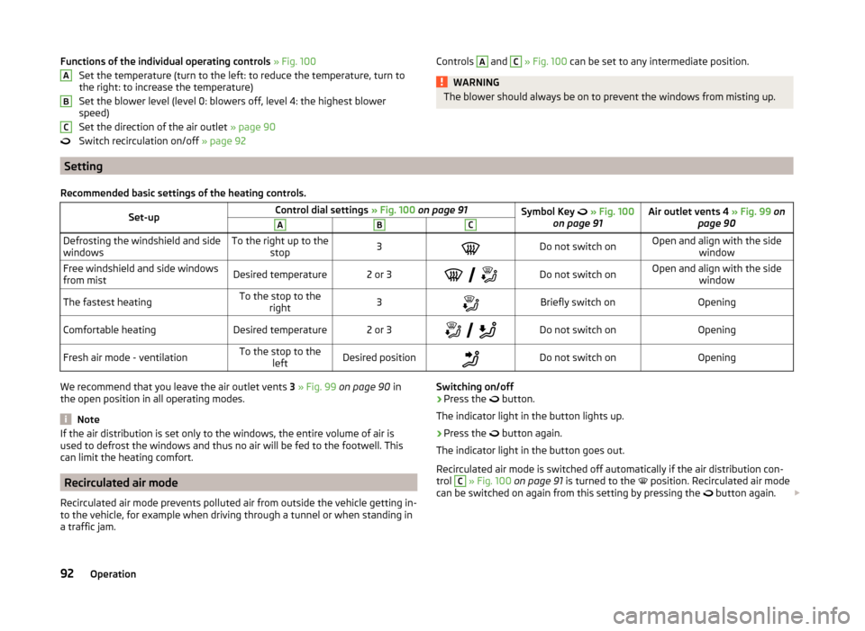
Functions of the individual operating controls » Fig. 100
Set the temperature (turn to the left: to reduce the temperature, turn to
the right: to increase the temperature)
Set the blower level (level 0: blowers off, level 4: the highest blower
speed)
Set the direction of the air outlet » page 90
Switch recirculation on/off » page 92ABCControls A and C » Fig. 100 can be set to any intermediate position.WARNINGThe blower should always be on to prevent the windows from misting up.
Setting
Recommended basic settings of the heating controls.Set-upControl dial settings » Fig. 100 on page 91Symbol Key » Fig. 100
on page 91Air outlet vents 4 » Fig. 99 on
page 90ABCDefrosting the windshield and side
windowsTo the right up to the stop3Do not switch onOpen and align with the side windowFree windshield and side windows
from mistDesired temperature2 or 3
Do not switch onOpen and align with the side
windowThe fastest heatingTo the stop to theright3Briefly switch onOpeningComfortable heatingDesired temperature2 or 3
Do not switch onOpeningFresh air mode - ventilationTo the stop to the
leftDesired positionDo not switch onOpeningWe recommend that you leave the air outlet vents 3 » Fig. 99 on page 90 in
the open position in all operating modes.
Note
If the air distribution is set only to the windows, the entire volume of air is
used to defrost the windows and thus no air will be fed to the footwell. This
can limit the heating comfort.
Recirculated air mode
Recirculated air mode prevents polluted air from outside the vehicle getting in-
to the vehicle, for example when driving through a tunnel or when standing in
a traffic jam.
Switching on/off›Press the button.
The indicator light in the button lights up.›
Press the
button again.
The indicator light in the button goes out.
Recirculated air mode is switched off automatically if the air distribution con-
trol
C
» Fig. 100 on page 91 is turned to the
position. Recirculated air mode
can be switched on again from this setting by pressing the
button again.
92Operation
Page 104 of 204
Creating a connection with an already paired mobile phone
After switching on the ignition, the connection is automatically established for the already paired mobile phone 1)
. Check on your mobile phone if the automat-
ic connection has been established.
Disconnecting the connection
› By withdrawing the ignition key.
› By disconnecting the hands-free system in the mobile phone.
› By disconnecting the user in the
Bluetooth - Users menu item in the MAXI
DOT display.
Solving connection problems
Check the operating status of the mobile phone if the system reports No
paired phone found .
› Is the mobile phone switched on?
› Is the PIN code entered?
› Is Bluetooth ®
active?
› Is the visibility of the mobile phone active?
› Has the mobile phone already been paired with the hands-free system?
Note
■
If a suitable adapter is available for your mobile phone, only use your mobile
phone in the adapter inserted in the telephone mount so that the radiation in
the vehicle drops to a minimum.■
Placing the mobile phone in the adapter inserted in the telephone mount en-
sures optimum sending and receiving power.
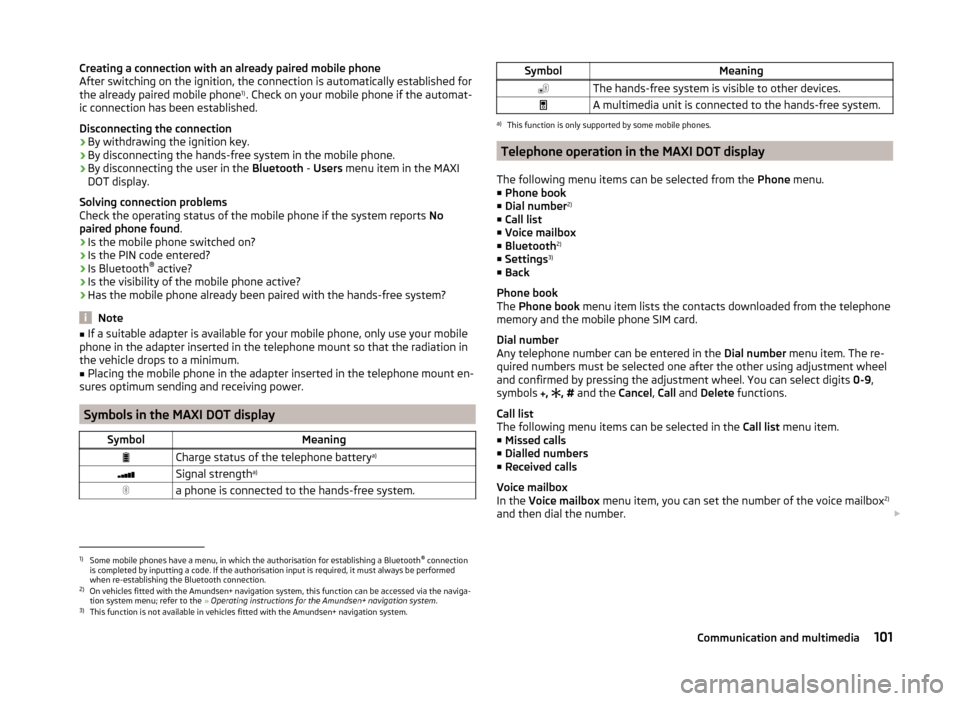
Symbols in the MAXI DOT display
SymbolMeaningCharge status of the telephone battery a)Signal strengtha)a phone is connected to the hands-free system.SymbolMeaningThe hands-free system is visible to other devices.A multimedia unit is connected to the hands-free system.a)
This function is only supported by some mobile phones.
Telephone operation in the MAXI DOT display
The following menu items can be selected from the Phone menu.
■ Phone book
■ Dial number 2)
■ Call list
■ Voice mailbox
■ Bluetooth 2)
■ Settings 3)
■ Back
Phone book
The Phone book menu item lists the contacts downloaded from the telephone
memory and the mobile phone SIM card.
Dial number
Any telephone number can be entered in the Dial number menu item. The re-
quired numbers must be selected one after the other using adjustment wheel
and confirmed by pressing the adjustment wheel. You can select digits 0-9,
symbols ,
, #
and the Cancel, Call and Delete functions.
Call list
The following menu items can be selected in the Call list menu item.
■ Missed calls
■ Dialled numbers
■ Received calls
Voice mailbox
In the Voice mailbox menu item, you can set the number of the voice mailbox 2)
and then dial the number.
1)
Some mobile phones have a menu, in which the authorisation for establishing a Bluetooth®
connection
is completed by inputting a code. If the authorisation input is required, it must always be performed
when re-establishing the Bluetooth connection.
2)
On vehicles fitted with the Amundsen+ navigation system, this function can be accessed via the naviga-
tion system menu; refer to the » Operating instructions for the Amundsen+ navigation system .
3)
This function is not available in vehicles fitted with the Amundsen+ navigation system.
101Communication and multimedia
Page 109 of 204
Driving
Starting-off and Driving
Starting and stopping the engine
Introduction
This chapter contains information on the following subjects:
Electronic immobilizer
107
Ignition lock
107
Engine
107
Switching off the engine
107
The engine can only be started using a correctly coded original key.
The engine running noises may louder at first be louder for a short time after starting the cold engine. This is quite normal and is not an operating problem.
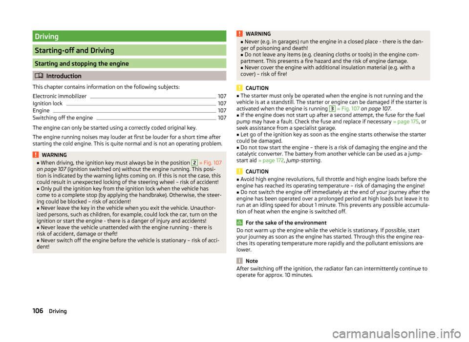
WARNING■ When driving, the ignition key must always be in the position 2 » Fig. 107
on page 107 (ignition switched on) without the engine running. This posi-
tion is indicated by the warning lights coming on. If this is not the case, this
could result in unexpected locking of the steering wheel – risk of accident!■
Only pull the ignition key from the ignition lock when the vehicle has
come to a complete stop (by applying the handbrake). Otherwise, the steer- ing could be blocked – risk of accident!
■
Never leave the key in the vehicle when you exit the vehicle. Unauthor-
ized persons, such as children, for example, could lock the car, turn on the
ignition or start the engine - there is a danger of injury and accidents!
■
Never leave the vehicle unattended with the engine running - there is
risk of accident, damage or theft!
■
Never switch off the engine before the vehicle is stationary – risk of acci-
dent!
WARNING■ Never (e.g. in garages) run the engine in a closed place - there is the dan-
ger of poisoning and death!■
Do not leave any items (e.g. cleaning cloths or tools) in the engine com-
partment. This presents a fire hazard and the risk of engine damage.
■
Never cover the engine with additional insulation material (e.g. with a
cover) – risk of fire!
CAUTION
■ The starter must only be operated when the engine is not running and the
vehicle is at a standstill. The starter or engine can be damaged if the starter is
activated when the engine is running 3
» Fig. 107 on page 107 .
■
If the engine does not start up after a second attempt, the fuse for the fuel
pump may have a fault. Check the fuse and replace if necessary » page 175, or
seek assistance from a specialist garage.
■
Let go of the ignition key as soon as the engine starts otherwise the starter
could be damaged.
■
Do not tow start the engine – there is a risk of damaging the engine and the
catalytic converter. The battery from another vehicle can be used as a jump-
start aid » page 172 , Jump-starting .
CAUTION
■
Avoid high engine revolutions, full throttle and high engine loads before the
engine has reached its operating temperature – risk of damaging the engine!■
Do not switch the engine off immediately at the end of your journey after the
engine has been operated over a prolonged period at high loads but leave it to
run at an idling speed for about 1 minute. This prevents any possible accumula-
tion of heat when the engine is switched off.
For the sake of the environment
Do not warm up the engine while the vehicle is stationary. If possible, start
your journey as soon as the engine has started. Through this the engine rea-
ches its operating temperature more rapidly and the pollutant emissions are
lower.
Note
After switching off the ignition, the radiator fan can intermittently continue to
operate for approx. 10 minutes.106Driving
Page 110 of 204
Electronic immobilizerRead and observe
and on page 106 first.
An electronic chip is integrated in the head of the key. The immobiliser is deac-
tivated with the aid of this chip when the key is inserted in the ignition lock.
The electronic immobiliser is automatically activated when the ignition key is
withdrawn from the lock.
The engine will not start if a non-authorized ignition key is used.
The MAXI DOT display shows the following: Immobilizer active.
Ignition lock
Fig. 107
Positions of the vehicle key in
the ignition lock
Read and observe and on page 106 first.
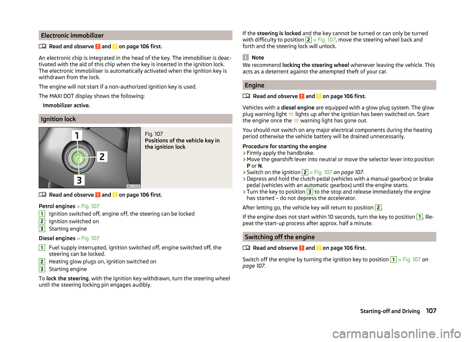
Petrol engines » Fig. 107
Ignition switched off, engine off, the steering can be locked
Ignition switched on
Starting engine
Diesel engines » Fig. 107
Fuel supply interrupted, ignition switched off, engine switched off, the
steering can be locked.
Heating glow plugs on, ignition switched on
Starting engine
To lock the steering , with the ignition key withdrawn, turn the steering wheel
until the steering locking pin engages audibly.
123123If the steering is locked and the key cannot be turned or can only be turned
with difficulty to position 2 » Fig. 107 , move the steering wheel back and
forth and the steering lock will unlock.
Note
We recommend locking the steering wheel whenever leaving the vehicle. This
acts as a deterrent against the attempted theft of your car.
Engine
Read and observe
and on page 106 first.
Vehicles with a diesel engine are equipped with a glow plug system. The glow
plug warning light lights up after the ignition has been switched on. Start
the engine once the warning light has gone out.
You should not switch on any major electrical components during the heating
period otherwise the vehicle battery will be drained unnecessarily.
Procedure for starting the engine
›
Firmly apply the handbrake.
›
Move the gearshift lever into neutral or move the selector lever into position
P or N.
›
Switch on the ignition
2
» Fig. 107 on page 107 .
›
Depress and hold the clutch pedal (vehicles with a manual gearbox) or brake
pedal (vehicles with an automatic gearbox) until the engine starts.
›
Turn the key to position
3
to the stop and release immediately the engine
has started – do not depress the accelerator.
After letting go, the vehicle key will return to position
2
.
If the engine does not start within 10 seconds, turn the key to position
1
. Re-
peat the start-up process after approx. half a minute.
Switching off the engine
Read and observe
and on page 106 first.
Switch off the engine by turning the ignition key to position
1
» Fig. 107 on
page 107 .
107Starting-off and Driving
Page 113 of 204
In the driver's footwell, only a footmat, which is attached to the two corre-
sponding attachment points, may be used.
Only use footmats from the range of ŠKODA Original Accessories, which are fit-
ted to two attachment points.WARNINGNo objects are allowed in the driver's footwell – risk of obstruction or limi-
tation in operating the pedals!
Automatic transmission
Introduction
This chapter contains information on the following subjects:
Modes and use of selector lever
110
Manual shifting (Tiptronic)
111
Starting-off and driving
112
Malfunction
112
Selector lever-emergency unlocking
112WARNING■ Do not depress the accelerator if the forward driving mode is changed
when the vehicle is halted and the engine is running – there is a risk of an
accident.■
Never shift the selector lever to R or P modes when driving – there is a
risk of an accident.
■
The vehicle must be held on the brake pedal in D, S or R modes if the ve-
hicle is halted and the engine is running. Even when the engine is idling,
power transmission is never completely interrupted – the vehicle will creep.
CAUTION■ If the selector lever is shifted to N while the vehicle is being driven you must
lift off the accelerator pedal and you will need to wait until the engine has
reached its idling speed before shifting the selector lever to a forward driving
mode again.■
At temperatures below -10 °C, the engine can only be started in selector lev-
er position P.
■
Never try to hold the vehicle using the accelerator pedal when stopping on a
hill – this may lead to transmission damage.
Note
After the ignition is switched off, the ignition key can only be withdrawn if the
selector lever is in position P1)
.
Modes and use of selector lever
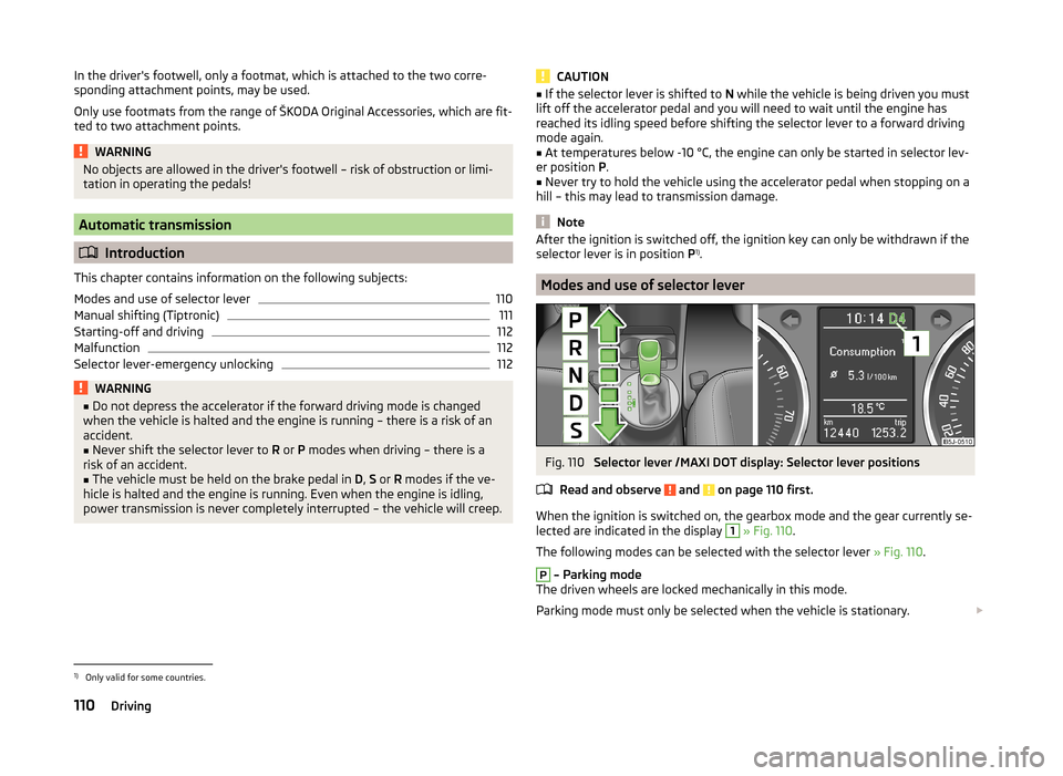
Fig. 110
Selector lever /MAXI DOT display: Selector lever positions
Read and observe
and on page 110 first.
When the ignition is switched on, the gearbox mode and the gear currently se- lected are indicated in the display
1
» Fig. 110 .
The following modes can be selected with the selector lever » Fig. 110.
P
– Parking mode
The driven wheels are locked mechanically in this mode.
Parking mode must only be selected when the vehicle is stationary.
1)
Only valid for some countries.
110Driving
Page 128 of 204
Error: Start-Stop
ERROR START-STOP
A system error is present. Seek help from a specialist garage.
Tyre pressure monitoring
Introduction
This chapter contains information on the following subjects:
Save tyre pressure values
125
The tyre pressure monitoring function (hereinafter referred to only as a sys-
tem) monitors the tyre pressure while driving.
If the rolling circumference of a wheel is changed, the indicator light in the
instrument cluster lights up and an audible signal sounds.
Information on the procedure for the notification of change of tyre inflation
pressure » page 45 .
The system can only function properly if the tyres have the prescribed inflation
pressure and this pressure values are stored in the system.
WARNING■ The driver is always responsible for the tyre inflation pressure. Tyre pres-
sure should be checked regularly » page 157.■
The system cannot warn in case of very rapid loss of tyre pressure, e.g. in
the event of a sudden puncture.
Save tyre pressure values
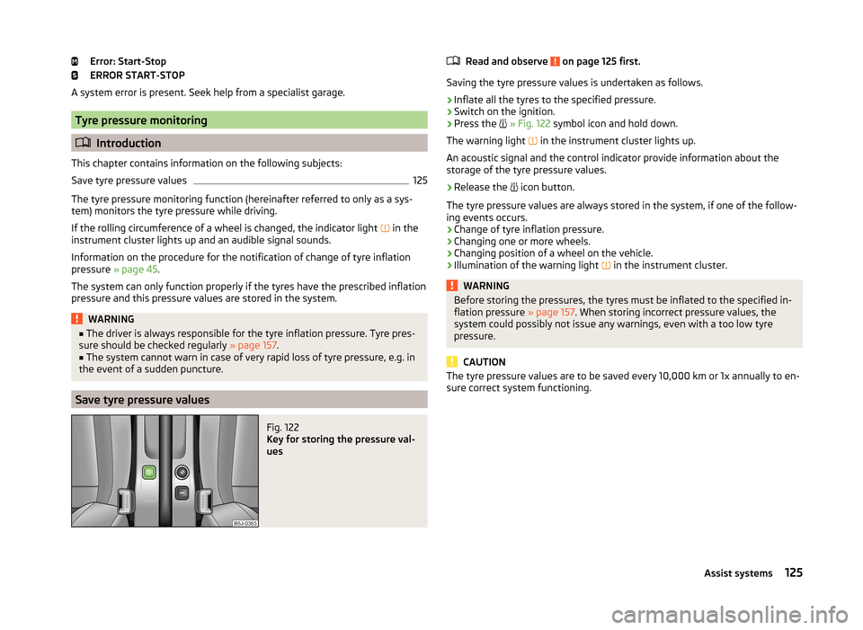
Fig. 122
Key for storing the pressure val-
ues
Read and observe on page 125 first.
Saving the tyre pressure values is undertaken as follows.
›
Inflate all the tyres to the specified pressure.
›
Switch on the ignition.
›
Press the
» Fig. 122 symbol icon and hold down.
The warning light
in the instrument cluster lights up.
An acoustic signal and the control indicator provide information about the
storage of the tyre pressure values.
›
Release the
icon button.
The tyre pressure values are always stored in the system, if one of the follow-
ing events occurs.
› Change of tyre inflation pressure.
› Changing one or more wheels.
› Changing position of a wheel on the vehicle.
› Illumination of the warning light
in the instrument cluster.
WARNINGBefore storing the pressures, the tyres must be inflated to the specified in-
flation pressure » page 157. When storing incorrect pressure values, the
system could possibly not issue any warnings, even with a too low tyre
pressure.
CAUTION
The tyre pressure values are to be saved every 10,000 km or 1x annually to en-
sure correct system functioning.125Assist systems
Page 130 of 204
Key
locking ball
Note
■ The tool for removing the wheel trim is part of the vehicle tool
kit » page 166 .■
If you lose the key, please get in touch with a specialist garage.
Adjusting the ready position
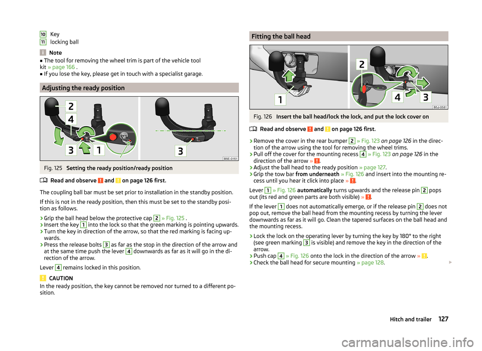
Fig. 125
Setting the ready position/ready position
Read and observe
and on page 126 first.
The coupling ball bar must be set prior to installation in the standby position. If this is not in the ready position, then this must be set to the standby posi-
tion as follows.
›
Grip the ball head below the protective cap
2
» Fig. 125 .
›
Insert the key
1
into the lock so that the green marking is pointing upwards.
›
Turn the key in direction of the arrow, so that the red marking is facing up-
wards.
›
Press the release bolts
3
as far as the stop in the direction of the arrow and
at the same time push the lever
4
downwards as far as it will go in the di-
rection of the arrow.
Lever
4
remains locked in this position.
CAUTION
In the ready position, the key cannot be removed nor turned to a different po-
sition.1011Fitting the ball headFig. 126
Insert the ball head/lock the lock, and put the lock cover on
Read and observe
and on page 126 first.
›
Remove the cover in the rear bumper
2
» Fig. 123 on page 126 in the direc-
tion of the arrow using the tool for removing the wheel trims.
›
Pull off the cover for the mounting recess
4
» Fig. 123 on page 126 in the
direction of the arrow » .
›
Adjust the ball head to the ready position » page 127.
›
Grip the tow bar from underneath » Fig. 126 and insert into the mounting re-
cess until you hear it click into place » .
Lever
1
» Fig. 126 automatically turns upwards and the release pin
2
pops
out (its red and green parts are both visible) » .
If the lever
1
does not automatically emerge, or if the release pin
2
does not
pop out, remove the ball head from the mounting recess by turning the lever
downwards as far as it will go. Clean the tapered surfaces on the ball head and
the mounting recess.
›
Lock the lock on the operating lever by turning the key by 180° to the right
(see green marking
3
is visible) and remove the key in the direction of the
arrow.
›
Push cap
4
» Fig. 126 onto the lock in the direction of the arrow » .
›
Check the ball head for secure mounting » page 128.
127Hitch and trailer
Page 131 of 204
WARNING■Carefully remove the cap for the mounting recess - there is a risk of hand
injury.■
Keep your hands outside the lever's range of motion when attaching the
ball head – there is a risk of fingers being injured!
■
Never attempt to pull the operating lever upwards forcibly to turn the
key. Doing so would mean the ball head is not attached correctly.
CAUTION
■ After removing the key, always replace the cover on the lock – there is a risk
of the lock getting dirty.■
Remove the cover from the rear bumper with care - there is a risk of paint
damage to the bumper and the cap.
Note
Store cover 2 and cover 4 » Fig. 123 on page 126 in a suitable place in the
luggage compartment after removing them.
Check proper fitting
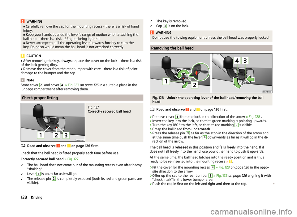
Fig. 127
Correctly secured ball head
Read and observe and on page 126 first.
Check that the ball head is fitted properly each time before use.
Correctly secured ball head » Fig. 127
The ball head does not come out of the mounting recess even after heavy
“shaking”.
Lever
1
is up as far as it will go.
The release pin
2
is completely exposed (both its red and green parts are
visible).
The key is removed.
Cap 3
is on the lock.WARNINGDo not use the towing equipment unless the ball head was properly locked.
Removing the ball head
Fig. 128
Unlock the operating lever of the ball head/removing the ball
head
Read and observe
and on page 126 first.
›
Remove cover
1
from the lock in the direction of the arrow » Fig. 128 .
›
Insert the key into the lock, so that its green marking is pointing upwards.
›
Turn the key 180 ° to the left, so that its red marking
2
is visible.
›
Grasp the ball head from underneath.
›
Press the release pin
3
as far as the stop in the direction of the arrow and
at the same time push the lever
4
downwards as far as it will go in the di-
rection of the arrow.
The ball head is released in this position and falls freely into the hand. If it
does not fall freely into the hand, use your other hand to push it upwards.
At the same time, the ball head latches into the ready position and is thus
ready to be re-inserted into the mounting recess »
.
›
Fit the cover for the mounting recess
4
» Fig. 123 on page 126 in the oppo-
site direction to the arrow.
›
Offer up the cap to the rear bumper
2
» Fig. 123 on page 126 aligning it with
“check mark” in the lower bumper area.
›
Push the cap in first on the left and right and then at the top.
128Driving
Page 132 of 204
WARNING■Never allow the ball head to remain unsecured in the boot. This could
cause damage to the boot upon sudden braking, and could put the safety
of the occupants at risk.■
Never remove the tow bar while the trailer is still coupled.
CAUTION
■ If the lever is held firmly and not pushed downwards as far as it can go, it will
go back up after the ball head is removed and will not latch into the ready po-
sition. The ball head then needs to be brought into this position before the
next time it is fitted » page 127, Adjusting the ready position .■
Tuck the ball bar in the ready position, with the golden key up, in the box -
otherwise there is a risk of damage to the key!
■
Do not use excessive force when handling the operating lever (e.g. do not
step on it).
Note
■ We recommend that you put the protective cap on the ball before removing
the ball head.■
Clean any dirt from the ball head before stowing it away in the box with the
vehicle tool kit.
Accessories
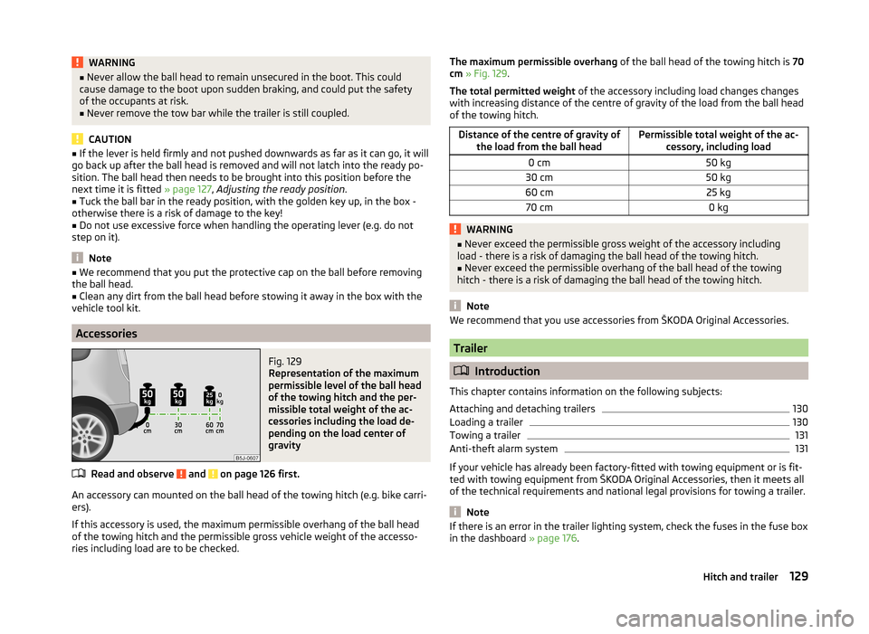
Fig. 129
Representation of the maximum
permissible level of the ball head
of the towing hitch and the per-
missible total weight of the ac-
cessories including the load de-
pending on the load center of
gravity
Read and observe and on page 126 first.
An accessory can mounted on the ball head of the towing hitch (e.g. bike carri- ers).
If this accessory is used, the maximum permissible overhang of the ball head
of the towing hitch and the permissible gross vehicle weight of the accesso-
ries including load are to be checked.
The maximum permissible overhang of the ball head of the towing hitch is 70
cm » Fig. 129 .
The total permitted weight of the accessory including load changes changes
with increasing distance of the centre of gravity of the load from the ball head
of the towing hitch.Distance of the centre of gravity of the load from the ball headPermissible total weight of the ac- cessory, including load0 cm50 kg30 cm50 kg60 cm25 kg70 cm0 kgWARNING■Never exceed the permissible gross weight of the accessory including
load - there is a risk of damaging the ball head of the towing hitch.■
Never exceed the permissible overhang of the ball head of the towing
hitch - there is a risk of damaging the ball head of the towing hitch.
Note
We recommend that you use accessories from ŠKODA Original Accessories.
Trailer
Introduction
This chapter contains information on the following subjects:
Attaching and detaching trailers
130
Loading a trailer
130
Towing a trailer
131
Anti-theft alarm system
131
If your vehicle has already been factory-fitted with towing equipment or is fit-
ted with towing equipment from ŠKODA Original Accessories, then it meets all
of the technical requirements and national legal provisions for towing a trailer.
Note
If there is an error in the trailer lighting system, check the fuses in the fuse box
in the dashboard » page 176.129Hitch and trailer
Page 134 of 204
The towed weight comprises the actual weights of the (loaded) towing vehicle
and the (loaded) trailer.
The trailer and drawbar load information on the type plate of the towing
equipment are merely test data for the towing equipment. The vehicle-specific
values are detailed in the vehicle documents.WARNING■ The maximum permissible axle and drawbar load and the permissible
weight of the trailer must not exceed - this could cause an accident!■
A sliding cargo can significantly adversely affect stability and driving safe-
ty - there is a risk of accident!
Towing a trailer
Driving speed
For safety reasons, do not drive faster than 80 km/h when towing a trailer.
Immediately reduce your speed as soon as even the slightest swaying of the
trailer is detected. Never attempt to stop the trailer from “swaying” by acceler-
ating.
Brakes
Apply the brakes in good time! If the trailer is fitted with a trailer brake, apply
the brakes gently at first, then brake firmly. This will avoid brake jolts resulting
from the trailer wheels locking.
On downhill sections shift down a gear in good time to also use the engine as
a brake.
Engine overheating
The speed must be reduced immediately if the needle for the coolant tempera-
ture gauge moves into the right-hand area or the red area of the scale.
Stop and switch off the engine if the warning light in the instrument cluster
starts to flash. Wait a few minutes and check the level of coolant » page 151,
Checking the coolant level .
Further information » page 41,
Coolant
.
The coolant temperature can be reduced by switching on the heating.
WARNING■ Always drive particularly carefully with the trailer.■Adapt your speed to the conditions of the road surface and to the traffic
situation.
Note
If you tow a trailer frequently, you should also have your vehicle inspected be-
tween service intervals.
Anti-theft alarm system
When the vehicle is locked, the alarm is activated when the electrical connec-
tion to the trailer is interrupted.
Always switch off the anti-theft alarm system before a trailer is coupled or un-
coupled » page 53 .
Conditions for including a trailer in the anti-theft alarm system. The vehicle is factory-fitted with an anti-theft alarm system and towing
equipment.
The trailer is electrically connected to the towing vehicle by means of the
trailer socket.
The electrical system of the vehicle and trailer is functional.
The vehicle is locked with the vehicle key and the anti-theft alarm system
is activated.
CAUTION
For technical reasons, trailers with rear LED lights cannot be connected to the
anti-theft alarm system.131Hitch and trailer