parking brake switch SKODA SUPERB 2015 3.G / (B8/3V) User Guide
[x] Cancel search | Manufacturer: SKODA, Model Year: 2015, Model line: SUPERB, Model: SKODA SUPERB 2015 3.G / (B8/3V)Pages: 276, PDF Size: 42.14 MB
Page 138 of 276

WARNING (Continued)■If the vehicle is in the D, S , R or Tiptronic mode and comes to a standstill
while at idle the engine stops, then prevent the vehicle from rolling away
with the brake pedal, the parking brake of the auto-hold function. Even
when the engine is idling, the power transmission is never completely in-
terrupted – the vehicle creeps.■
When leaving the vehicle, the selector lever is always to put in the P
mode. Otherwise, the vehicle could start to move - risk of accident.
CAUTION
■ If the selector lever is moved to mode N while driving, the accelerator pedal
must be released and you will need to wait until the engine has reached its
idling speed before moving the selector lever to a forward driving mode again.■
When the outdoor temperature is below -10 ° C, the selector lever when
starting must always be in P mode.
■
When stopping on a slope, never try to hold the vehicle using the accelerator
pedal – this may lead to gear damage.
Note
After the ignition is switched off, the ignition key can only be withdrawn if the
selector lever is in the position P.
Modes and use of selector lever
Fig. 169
Selector lever/display
Read and observe and on page 135 first.
When the ignition is switched on, the gearbox mode and the currently selected
gear are indicated in the display » Fig. 169.
The following modes can be selected with the selector lever » Fig. 169.
P – Parking mode
The driven wheels are locked mechanically in this mode.
The parking mode must only be selected when the vehicle is stationary.R
- Reverse gear
Reverse gear can only be engaged when the vehicle is stationary and the en-
gine is at idling speed.
N
- Neutral
The power transmission to the drive wheels is interrupted in this mode.
D
/
S
- mode for driving forward (Normal program) / mode for driving
forward (Sport program)
The system switches from one mode to the other by moving the selector lever
into the spring-loaded position
» Fig. 169 .
In mode D or S, the forward gears are shifted automatically depending on the
engine load, the operation of the accelerator pedal, the vehicle speed, and the
selected driving mode .
In mode S , the forward gears are shifted automatically up and down at high-
er engine speeds than in mode D.
If the Sport driving mode is selected with the engine running » page 171, Se-
lection of the driving mode(Driving Mode Selection) , the transmission is auto-
matically set in the S mode.
E – Economical driving mode
If the driving mode Eco or Individual (engine - Eco) » page 171 is selected and
the selection lever is in the setting D/S, the transmission is automatically set
to mode E. This mode cannot be selected with the selector lever.
In mode E , the forward gears are shifted automatically up and down at lower
engine speeds than in mode D.
136Driving
Page 148 of 276

The automatic brake interventions can take place only if the following condi-
tions are met.
There was a front, side and rear-end collision of a certain severity.
The impact speed was higher than approx. 10 km/h.
The brakes, the ESL and other required electrical systems remain function-
al after impact.
The accelerator pedal is not actuated.
Trailer stabilization system (TSA)
Read and observe
on page 144 first.
The TSA helps the combination stable in situations where the trailer sways
and then the whole trailer combination.
TSA brakes the individual wheels of the towing vehicle in order to damp the rocking motion of the entire vehicle combination.
The following conditions are required for the correct TSA function. The trailer was shipped from the factory or purchased from the ŠKODA
genuine accessories.
The trailer is electrically connected to the towing vehicle via the trailer
socket.
The parking aid is activated.
The speed is higher than approx. 60 km/h.
Further information » page 184, Hitch and trailer .
Auto Hold function
Fig. 176
The Auto-Hold function button
Read and observe on page 144 first.
The Auto Hold function (hereinafter referred to only as system) prevents the
vehicle from rolling unintentionally when stopped. It is, for example, not nec-
essary to secure the vehicle with the brake pedal or parking brake at traffic
lights.
For the activation, deactivation and correct functioning of the system, the
following basic conditions are required.
The driver's door is closed.
The engine is running (or shut-down automatically by the START-STOP
system).
On vehicles with automatic transmission the selector lever is not in mode
N (in this mode, the system is not available).
Stopping and starting
When stopping the system prevents the vehicle from rolling away. The warn- ing light illuminates in the instrument cluster. The brake pedal can be re-
leased.
The vehicle's brakes are released at the moment of stating off. The warning
light in the instrument cluster goes out.
Should the vehicle start to roll away when starting on a downhill slope then
step on the accelerator or and turn on the parking brake.
If the vehicle is secured by the system and the driver's door is opened or the ignition is turned off, the vehicle is secured by the parking brake to prevent
unwanted movement.
In this case, the indicator light turns off in the instrument cluster and the
warning light illuminates.
Activation/deactivation
The activation and deactivation of the system is done by pressing the symbol
key
» Fig. 176 .
When the system is activated, the symbol illuminates.
After switching off and switching on the ignition system several times the sys-
tem remains either activated or deactivated depending on the last setting.
146Driving
Page 157 of 276
›Stop the vehicle and steer opposite until the yellow lines 6 the red line 8fade into each other (required roadway alignment). Hold the steering wheel
in this position.
Orientation lines are displayed » Fig. 187 on page 153 in the display.›
Carefully move backwards.
›
Stop the vehicle when
appears the display, or at a safe distance from the
obstacle situated behind the vehicle.
Note
The guidance in the parking space is cancelled due to the system when the
steering wheel is set for a period of time against the required road direction.
The parking is to be started again.
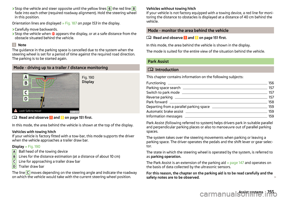
Mode - driving up to a trailer / distance monitoring
Fig. 190
Display
Read and observe and on page 151 first.
In this mode, the area behind the vehicle is shown at the top of the display.
Vehicles with towing hitch
If your vehicle is factory fitted with a tow-bar, this mode supports the driver
when the vehicle approaches a trailer draw bar.
Display » Fig. 190
Ball head of the towing device
Lines for the distance estimation (at a distance of about 10 cm)
Line for approaching a trailer draw bar
Trailer draw bar
The line
C
moves depending on the steering angle and indicate the roadway
on which the vehicle would take with the current steering wheel position.
ABCDVehicles without towing hitch
If your vehicle is not factory equipped with a towing device, a red line for moni-
toring the distance to obstacles is displayed at a distance of 40 cm behind the
vehicle.
Mode - monitor the area behind the vehicle
Read and observe
and on page 151 first.
In this mode, the area behind the vehicle is shown in the display.
The mode is suited for the entire view of the situation behind the vehicle.
Park Assist
Introduction
This chapter contains information on the following subjects:
Functioning
156
Parking space search
157
Switch to park mode
157
Reverse parking
157
Park forward
158
Departing from a parallel parking space
159
Automatic brake assist
159
Information messages
159
Park Assist (following referred to system) helps drivers park in suitable parallel
and perpendicular parking places or also to manoeuvre out of parallel parking
spaces.
The system takes over the steering movements when parking or leaving a
parking space. The driver operates the pedals and the shift lever or gear selec-
tor.
The state in which the steering wheel is operated by the system, is referred to
as parking operation.
The Park Assist is an extension of the parking aid » page 147 and operates on
the basis of data collected by the ultrasonic sensors.
For this reason, the chapter on the parking aid is to be read carefully and the safety notes are to be observed.
155Assist systems
Page 208 of 276
After refilling›After refilling AdBlue®
put the cap on the fuel filler neck and turn in the oppo-
site direction of the arrow 3
until it engages.
›
Close the fuel filler flap until it clicks into place.
Before driving
›
After filling AdBlue ®
only switch on the ignition and leave it on for at least 30
s, so that the refilling can be recognized by the system.
Only then start the engine.
CAUTION
The AdBlue ®
- tank is full when no AdBlue ®
flows from the refill bottle or as
soon as the correctly operated pump cuts out for the first time. Do not contin-
ue refilling AdBlue ®
.
Note
The working life of the AdBlue ®
solution is 4 years. Thereafter the solution
must be replaced by a specialist garage.
Engine compartment
Introduction
This chapter contains information on the following subjects:
Opening and closing the bonnet
207
Engine compartment overview
208
Radiator fan
208
Windscreen washer system
208WARNINGInjuries or scolding or risks of accident or fire may occur when working in
the engine compartment. For this reason, it is essential to comply with the
warning instructions outlined below and with the general applicable safety
rules. The engine compartment of your car is a hazardous area!WARNINGInstructions before beginning work in the engine compartment■Turn off the engine and remove the ignition key.■
The parking brake switch.
WARNING (Continued)■ For vehicles with manual transmission the lever into the neutral position.■On vehicles with automatic transmission, shift the selector lever into the
P position.■
Allow the engine to cool.
■
Never open the bonnet if you can see steam or coolant escaping from the
engine compartment – risk of scalding! Wait until no more steam or coolant
is escaping.
WARNINGInformation for working in the engine room■Keep all people, especially children, away from the engine compartment.■
Never touch the radiator fan. The fan might suddenly start running!
■
Do not touch any hot engine parts – risk of burns!
WARNINGInformation for working in the engine compartment with the engine run-
ning■
Pay particular attention to moving engine parts, e.g. V-ribbed belt, gener-
ator, radiator fan - danger to life!
■
Never touch the electric wiring on the ignition system.
■
Avoid short circuits in the electrical system, particularly on the vehicle's
battery.
■
Always make sure that no jewellery, loose clothing or long hair can get
caught in rotating engine parts – risk to life! Always remove any jewellery,
tie back long hair and wear tight fitting clothing before completing any
work.
WARNINGInformation for working on the fuel system or the electrical system■Always disconnect the vehicle battery from the electrical system.■
Do not smoke.
■
Never work near open flames.
■
Always have a functioning fire extinguisher nearby.
206General Maintenance
Page 226 of 276

WARNINGThe factory-supplied lifting jack is only intended for your model of vehicle.
Under no circumstances attempt to lift heavier vehicles or other loads.
CAUTION
■ Screw the jack back into the starting position before storing in the box with
the tool kit.■
Ensure that the vehicle tool kit is safely secured in the boot.
■
Ensure that the box is always secured with the strap.
Note
The declaration of conformity is included with the jack or the log folder.
Changing a wheel
Introduction
This chapter contains information on the following subjects:
Preparation
224
Removing/stowing the wheel
224
Full wheel trim
225
Wheel bolts
225
Anti-theft wheel bolts
225
Loosening/tightening wheel bolts
226
Raising the vehicle
226
Remove the wheel / fix
227
Follow-up tasks
227
For your own safety and the safety of the passengers, the following instruc-
tions must be observed before changing a wheel on the road.
Switch on the hazard warning lights system.
Place the warning triangle at the prescribed distance.
Park the vehicle as far away as possible from the flowing traffic.
Choose a location with a flat, solid surface.
Have all the occupants get out. The passengers should not stand on the
road (instead they should remain behind a crash barrier, for instance) while
the wheel is being changed.
Tyres with increased puncture resistance
Some vehicles may be fitted with tyres at the factory that have increased
puncture resistance (so-called “SEAL” tyres).
These vehicles are delivered without a puncture repair kit, spare wheel and
appropriate hand tools.
If the tyres with increased puncture resistance are replaced with tyres that
have no increased puncture resistance then the vehicle should be equipped
with a puncture repair kit, spare wheel and appropriate hand tools.
Preparation
Before changing the wheel, the following work must be carried out.
›
Switch off the engine.
›
For vehicles with manual transmission engage 1st gear.
›
On vehicles with
automatic transmission place the selector lever in the P po-
sition.
›
The parking brake switch.
›
Uncouple any trailers.
Removing/stowing the wheel
Fig. 242
Take out wheel
The wheel is located in a well under the floor covering in the boot and is fixed
in place with a special screw.
Take out wheel
›
Open the tailgate.
›
Lift up the floor in the luggage compartment.
›
Loosen the retaining belt and take out the box with the tool kit.
›
Unscrew the special screws in the direction of arrow » Fig. 242.
›
Remove the wheel.
224Do-it-yourself
Page 231 of 276
General informationRead and observe
on page 228 first.
For your own safety and the safety of your passengers, the following instruc-
tions must be observed before carrying out a wheel repair on the road.
Switch on the hazard warning lights system.
Place the warning triangle at the prescribed distance.
Park the vehicle as far away as possible from the flowing traffic.
Choose a location with a flat, solid surface.
Have all the occupants get out. The passengers should not stand on the
road (instead they should remain behind a crash barrier, for instance) while
the wheel is being changed.
The breakdown kit must not be used under the following circumstances. ▶ The rim is damaged.
▶ The outside temperature is below -20 ° C.
▶ The cut or puncture is larger than 4 mm.
▶ The tyre wall is damaged.
▶ After the expiration date (see inflation bottle).
Preparations for using the breakdown kit
Read and observe
on page 228 first.
The following preparatory work must be carried out before using the puncturerepair kit.
›
Switch off the engine.
›
For vehicles with manual transmission engage 1st gear.
›
On vehicles with
automatic transmission place the selector lever in the P po-
sition.
›
The parking brake switch.
›
Check that you can carry out the repairs with the breakdown kit » page 228.
›
Uncouple any trailers.
›
Remove the breakdown kit from the boot.
›
Stick the sticker
1
» Fig. 248 on page 228 on the dashboard in the driver's
field of view.
›
Unscrew the valve cap.
›
Use the valve remover
2
to unscrew the valve core and place it on a clean
surface (rag, paper, etc.).
Sealing and inflating the tyre
Read and observe
on page 228 first.
Sealing
›
Forcefully shake the tyre inflation bottle
10
» Fig. 248 on page 228 back and
forth several times.
›
Firmly screw the inflation hose
3
onto the tyre inflater bottle
10
. The film on
the cap is pierced automatically.
›
Remove the plug from the inflation hose
3
and plug the open end fully onto
the tyre valve.
›
Hold the bottle
10
with the bottom facing upwards and fill all of the sealing
agent from the tyre inflator bottle into the tyre.
›
Remove the filler plug from the tyre valve.
›
Screw the valve core back into the tyre valve using the valve remover
2
.
Inflating
›
Screw the air compressor tyre inflation hose
7
» Fig. 248 on page 228 firmly
onto the tyre valve.
›
For vehicles with manual transmission the lever into the neutral position.
›
On vehicles with automatic transmission place the selector lever in the P po-
sition.
›
Start the engine and run it in idle.
›
Plug the connector
6
into 12 volt socket » page 100.
›
Switch on the air compressor with the ON and OFF switch
9
.
›
Allow the air compressor to run until a pressure of 2.0 - 2.5 bar is achieved.
Maximum run time of 8 minutes » .
›
Switch off the air compressor.
›
If you cannot reach an air pressure of 2.0 - 2.5 bar, unscrew the tyre inflation
hose
7
from the tyre valve.
›
Drive the vehicle 10 metres forwards or backwards to allow the sealing agent
to “distribute” in the tyre.
›
Firmly screw the tyre inflation hose
7
back onto the tyre valve and repeat
the inflation process.
›
Switch off the air compressor.
›
Remove the tyre inflation hose
7
from the tyre valve.
Once a tyre inflation pressure of 2.0 - 2.5 bar is achieved, you can continue the journey.
229Emergency equipment and self-help
Page 239 of 276

›Fold the rear seat backrest forward
» page 85.›Insert a screwdriver or similar tool into the recess or the opening in the trim
» Fig. 262 as far as the stop.›
Unlock the lid by moving it in the direction of the arrow.
›
Open the tailgate.
Selector lever-emergency unlocking
Fig. 263
Selector lever-emergency unlocking
›
The parking brake switch.
›
Insert a flat-head screwdriver or similar tool into the gap in the arrow area
1
» Fig. 263 and lift the cover in arrow direction
2
.
›
Using a flat-head screwdriver or similar tool push on the yellow plastic part in
the direction of arrow
3
.
›
At the same time, press the locking button in the selector lever and move
the selector lever to position N.
If the selector lever is moved again to position P, it is once again blocked.
CAUTION
Make sure when lifting not to damage cover parts by the screwdriver in the
shift lever environment.
Replacing windscreen wiper blades
Introduction
This chapter contains information on the following subjects:
Replacing the windscreen wiper blades
237
Replacing the rear window wiper blade
238WARNINGReplace the windscreen wiper blades once or twice a year for safety rea-
sons. These can be purchased from a ŠKODA Partner.
Replacing the windscreen wiper blades
Fig. 264
Windscreen wiper blade
Read and observe
on page 237 first.
Adjust the windscreen wiper arms to the service position before replacing the
windscreen wiper blades.
Service position for changing wiper blades
›
Closing the bonnet.
›
Switch the ignition on and off again.
›
Within 10 seconds, press the lever in position
4
and hold it in position for
around 2 seconds » page 78, Windscreen wipers and washers .
The windscreen wiper arms move into the service position.
Removing the wiper blade
›
Lift the wiper arm from the windscreen in the direction of
1
» Fig. 264 .
›
Tilt the wiper blade to the stop in the same direction.
›
Hold the upper part of the wiper arm and press the securing mechanism
A
in the direction of arrow
2
.
›
Remove the wiper blade in the direction of the arrow
3
.
Attaching the windscreen wiper blade
›
Push the windscreen wiper blade to the stop until it locks into place.
›
Check that the windscreen wiper blade is correctly attached.
›
Fold the wiper arm back to the windscreen.
237Emergency equipment and self-help
Page 242 of 276
Installing the storage compartment›Raise the storage compartment in the direction of the arrow 4.›
Overcome the resistance of the detents
A
.
›
Insert the brake control linkage in the opposite direction to arrow
2
.
›
Lock the brake control linkage in the opposite direction to arrow
1
.
›
Close the storage compartment.
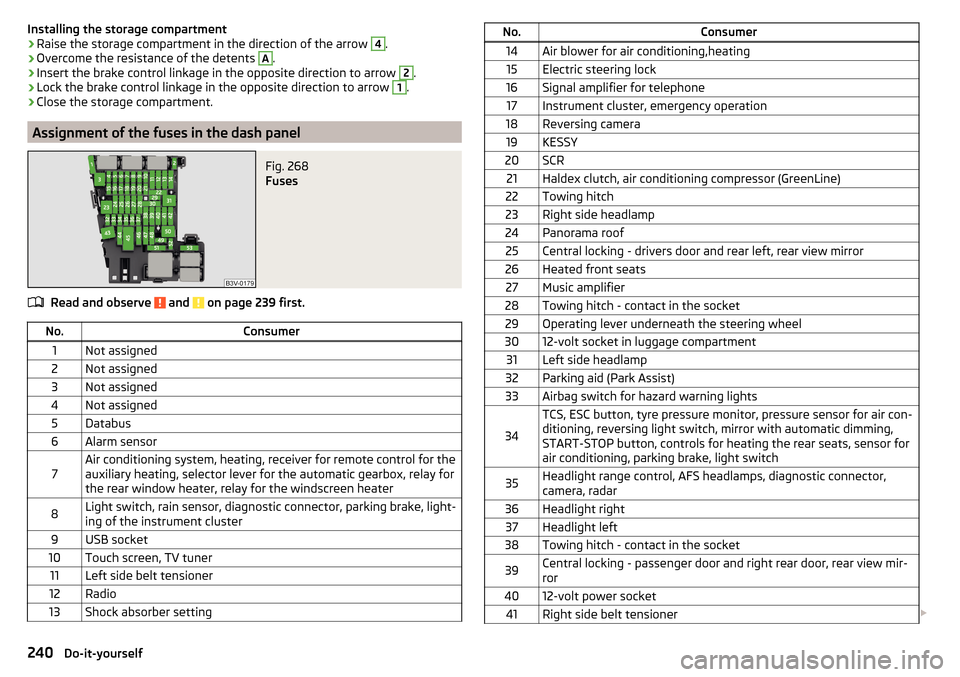
Assignment of the fuses in the dash panel
Fig. 268
Fuses
Read and observe and on page 239 first.
No.Consumer1Not assigned2Not assigned3Not assigned4Not assigned5Databus6Alarm sensor7Air conditioning system, heating, receiver for remote control for the
auxiliary heating, selector lever for the automatic gearbox, relay for
the rear window heater, relay for the windscreen heater8Light switch, rain sensor, diagnostic connector, parking brake, light-
ing of the instrument cluster9USB socket10Touch screen, TV tuner11Left side belt tensioner12Radio13Shock absorber settingNo.Consumer14Air blower for air conditioning,heating15Electric steering lock16Signal amplifier for telephone17Instrument cluster, emergency operation18Reversing camera19KESSY20SCR21Haldex clutch, air conditioning compressor (GreenLine)22Towing hitch23Right side headlamp24Panorama roof25Central locking - drivers door and rear left, rear view mirror26Heated front seats27Music amplifier28Towing hitch - contact in the socket29Operating lever underneath the steering wheel3012-volt socket in luggage compartment31Left side headlamp32Parking aid (Park Assist)33Airbag switch for hazard warning lights
34
TCS, ESC button, tyre pressure monitor, pressure sensor for air con-
ditioning, reversing light switch, mirror with automatic dimming,
START-STOP button, controls for heating the rear seats, sensor for
air conditioning, parking brake, light switch35Headlight range control, AFS headlamps, diagnostic connector,
camera, radar36Headlight right37Headlight left38Towing hitch - contact in the socket39Central locking - passenger door and right rear door, rear view mir-
ror4012-volt power socket41Right side belt tensioner 240Do-it-yourself
Page 243 of 276
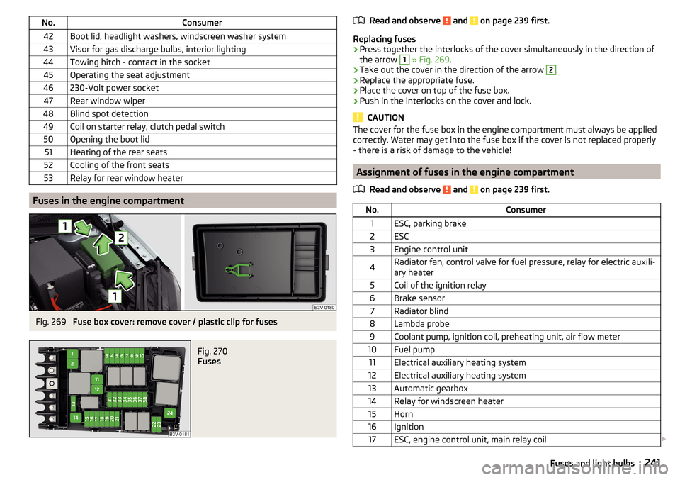
No.Consumer42Boot lid, headlight washers, windscreen washer system43Visor for gas discharge bulbs, interior lighting44Towing hitch - contact in the socket45Operating the seat adjustment46230-Volt power socket47Rear window wiper48Blind spot detection49Coil on starter relay, clutch pedal switch50Opening the boot lid51Heating of the rear seats52Cooling of the front seats53Relay for rear window heater
Fuses in the engine compartment
Fig. 269
Fuse box cover: remove cover / plastic clip for fuses
Fig. 270
Fuses
Read and observe and on page 239 first.
Replacing fuses
›
Press together the interlocks of the cover simultaneously in the direction of
the arrow
1
» Fig. 269 .
›
Take out the cover in the direction of the arrow
2
.
›
Replace the appropriate fuse.
›
Place the cover on top of the fuse box.
›
Push in the interlocks on the cover and lock.
CAUTION
The cover for the fuse box in the engine compartment must always be applied
correctly. Water may get into the fuse box if the cover is not replaced properly
- there is a risk of damage to the vehicle!
Assignment of fuses in the engine compartment
Read and observe
and on page 239 first.
No.Consumer1ESC, parking brake2ESC3Engine control unit4Radiator fan, control valve for fuel pressure, relay for electric auxili-
ary heater5Coil of the ignition relay6Brake sensor7Radiator blind8Lambda probe9Coolant pump, ignition coil, preheating unit, air flow meter10Fuel pump11Electrical auxiliary heating system12Electrical auxiliary heating system13Automatic gearbox14Relay for windscreen heater15Horn16Ignition17ESC, engine control unit, main relay coil 241Fuses and light bulbs
Page 259 of 276
automatic transmissionselector lever lock defect137
Automatic transmission135
Kick down138
Launch control138
Malfunctions37
Selector lever lock137
Warning light37
Warning messages37
AUX99
Auxiliary heating (auxiliary heating and ventila- tion)
123
Adjust124
Switching on/off124
Auxiliary heating (heating and ventilation) Radio remote control
125
Avoiding damage to your vehicle141
B
Bags on the backs of the front seats
97
on the inner sides of the front seats97
Battery In the remote control key
234
Replace the KESSY key234
Belts11
Belt tensioners14
Bonnet Closing
207
Opening207
Boot Class N1 vehicles
114
Non-contact opening61
See Boot lid59
Boot lid automatic locking
59
Closing59
Non-contact opening61
Opening59
Brake Information messages33
Warning light33
Brake Assist (HBA)145
Brake booster133
brake fluid specification
213
Brake fluid212
Checking212
Information messages33
Brake linings Warning light
36
Brake pedal (automatic transmission) Warning light
37
Brakes Brake booster
133
Brake fluid212
Braking and stabilisation systems143
Running-in139
Brakes and parking132
Brake system143
Braking Information on braking
132
Bulbs Replacing
242
C
Camera Lens care
197
Camera lens care
197
Car care Jack
197
Car computer see multifunction display
42
Care and maintenance190
Cargo element112
Car park134
Car park ticket holder91
Carrier Roof rack117
Cavity protection197
Central locking52
Problems57
Central locking button55
Change Bulb for indicator (halogen headlight)
243
engine oil209
light bulb in tail light244
Change engine oil
209
Changing Wheels
224
Changing a wheel Follow-up tasks
227
Preparation224
Changing wheels Wheel removal and fix
227
Charging a vehicle battery215
Checking Battery electrolyte level
214
Brake fluid212
Coolant211
Engine oil210
Oil level210
Windscreen washer fluid208
Checks Statutory checks
190
Children and safety20
Child safety Side airbag
22
Child safety lock57
Child safety seat Use of child safety seats
23
Child seat Classification
22
i-Size25
ISOFIX23
on the front passenger seat21
257Index