change wheel SKODA YETI 2010 1.G / 5L User Guide
[x] Cancel search | Manufacturer: SKODA, Model Year: 2010, Model line: YETI, Model: SKODA YETI 2010 1.G / 5LPages: 271, PDF Size: 14.71 MB
Page 155 of 271
Airbag system
154
being deployed. When the deployed head airbag is inflated, parts of the acces-
sories fitted may in certain circumstances be thrown into the interior of the car
and cause injuries to the occupants page 222, “Accessories, changes and
replacement of parts”.
Any work on the head airbag system including installing and removing
system components because of other repair work (e.g. removing headliner)
must only be carried out by a specialist garage.
Deactivating an airbagDeactivating airbags
If any airbags have been deactivated, switch them on again as soon as
possible so that they are able to again provide their proper protection.There is the technical means installed within your vehicle to switch off the front, side*
or head* airbag (take out of commission).
This is why you should have the deactivation of the airbags carried out by a specialist
garage.
On vehicles equipped with the switch for de activation of the airbags, you can deacti-
vate the front passenger airbag by means of this switch page 154.
Deactivation of airbags is envisaged only for particular instances, such as if:
Yo u m u s t i n exceptional cases use a child seat on the front passenger seat where
the child is seated with its back to the dire ction of travel (in some countries this must
be in the direction of travel due to other legal regulations applying) page 156,
“Important safety information regarding the use of child safety seats”;
you are not able to maintain the distance of at least 25 cm between middle of
steering wheel and chest, despite the driver seat being correctly adjusted;
special attachments are required in the ar ea of the steering wheel because of a
physical disability;
you have installed other seats (e.g. orthopaedic seats without side airbags). Monitoring the airbag system
The functionality of the airbag system is al
so monitored electronically when one airbag
has been switched off.
If the airbag was switched off using diagnostic equipment:
The warning light for the airbag system li ghts up for 4 seconds after switching on
the ignition and then flashes for 12 seco nds afterwards in 2 second intervals.
The following situation applies if the ai rbag has been switched off using the
switch for the airbag* in the storage compartment:
the airbag indicator light in the instrume nt cluster comes on for about 4 seconds
each time the igniti on is switched on;
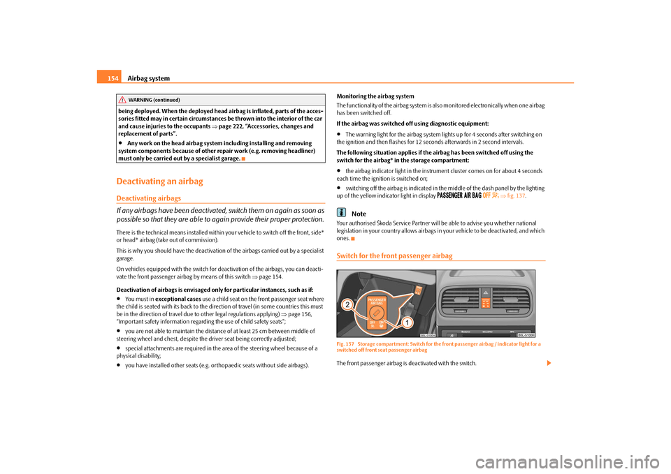
switching off the airbag is indicated in the middle of the dash panel by the lighting
up of the yellow indicator light in display
fig. 137 .
Note
Your authorised Škoda Service Partner will be able to advise you whether national
legislation in your country allows airbags in your vehicle to be deactivated, and which
ones.Switch for the front passenger airbagFig. 137 Storage compartment: Switch for the front passenger airbag / indicator light for a
switched off front seat passenger airbagThe front passenger airbag is deactivated with the switch.
WARNING (continued)
s2ug.6.book Page 154 Friday, April 9, 2010 2:24 PM
Page 165 of 271
Intelligent Technology
164
offered must not tempt you to take greater risks than otherwise - risk of an acci-
dent!
Note
All four wheels must be fitted with the same tyres in order to achieve problem-free
operation of the ESP. Differing rolling circum ferences of the tyres can lead to an unde-
sirable reduction in the engine output.
Changes to vehicle (e.g. on engine, on th e brakes, on chassis or another combina-
tion of tyres and wheels) can influence the function of the ESP page 222, “Accesso-
ries, changes and replacement of parts”.
Electronic Differential Lock (EDL)*
The electronic differential lock prev ents an individual wheel from slip-
ping.Models fitted with ESP ar e equipped with electronic differential lock (EDL).
General
The EDL makes it much easier, and sometimes at all possible, to start off, accelerate
and climb a steep hill when the conditions of the road surface are unfavourable.
Operating principle
The EDL is activated automaticall y, that is without any action on the part of the driver.
It monitors the speeds of the driven wheels with the aid of the ABS sensors. Should
only one drive wheel begin spinning on a slippery surface there will be an appreciable
difference in the speed of the driven wheels. The EDL function brakes the slipping
wheel and the differential transmits a greate r driving force to the other driven wheel.
This control process is also accompanied by noises.
Overheating of the brakes
The EDL switches off automatica lly if unusually severe stresses exist in order to avoid
excessive heat generation in the disc brake on the wheel which is being braked. The
vehicle can continue to be driven and has the same characteristics as a vehicle not
fitted with EDL. The EDL switches on again automatically
as soon as the brake has cooled down.
EDL Off-road*
After switching on the Off-road mode page 170, EDL Off-road is activated.
EDL Off-road is matched in such a way that it assists the traction of the vehicle when
driving on an unfirm ground.
EDL is activated earlier in the Off-road mode than in the normal mode. The brake pres-
sure builts up more quickly on the slipping wheel, on one axle, as well as diagonally.
WARNING
Carefully depress the accelerator when accelerating on uniformly slippery
road surfaces, such as ice and snow. Th e driven wheels might still spin despite
the EDL and affect the stability of the vehicle - risk of an accident!
You should always adapt your style of driving to the condition of road
surface and to the traffic situation even when your vehicle is fitted with EDL.
The increased safety offered must not tempt you to take greater risks than
otherwise - risk of an accident!Note
If the ABS or ESP warning light comes on, this may also indicate a fault in the EDL.
Please have the vehicle inspected as soon as possible by a specialist garage.
Changes to vehicle (e.g. on engine, on the brakes, on chassis or another combina-
tion of tyres and wheels) can influence the function of the EDL page 222, “Accesso-
ries, changes and replacement of parts”.
WARNING (continued)
s2ug.6.book Page 164 Friday, April 9, 2010 2:24 PM
Page 166 of 271
Intelligent Technology165
Using the system
Safety
Driving Tips
General Maintenance
Breakdown assistance
Technical Data
Traction control system (TCS)
The traction control system prevents the driven wheels from spinning
when accelerating.General
The TCS makes it much easier, and sometimes at all possible, to start off, accelerate and
climb a steep hill when th e conditions of the road surface are unfavourable.
Operating principle
The TCS switches on automatically when th e engine is started and then conducts a
self-test. The system monitors the speeds of the driven wheels with the aid of the ABS
sensors. If the wheels are spinning, the force transmitted to the road surface is auto-
matically adapted by reducing the engine speed. The system operates at all speeds.
The TCS operates in combination with the ABS page 167, “Antilock brake system
(ABS)”. The TCS will not function if a fault exists in the ABS system.
The TCS warning light lights up in the instru ment cluster when there is a fault on the
TCS
page 33.
During an intervention of the system, the TCS warning light
flashes in the instru-
ment cluster page 33.
Switching off
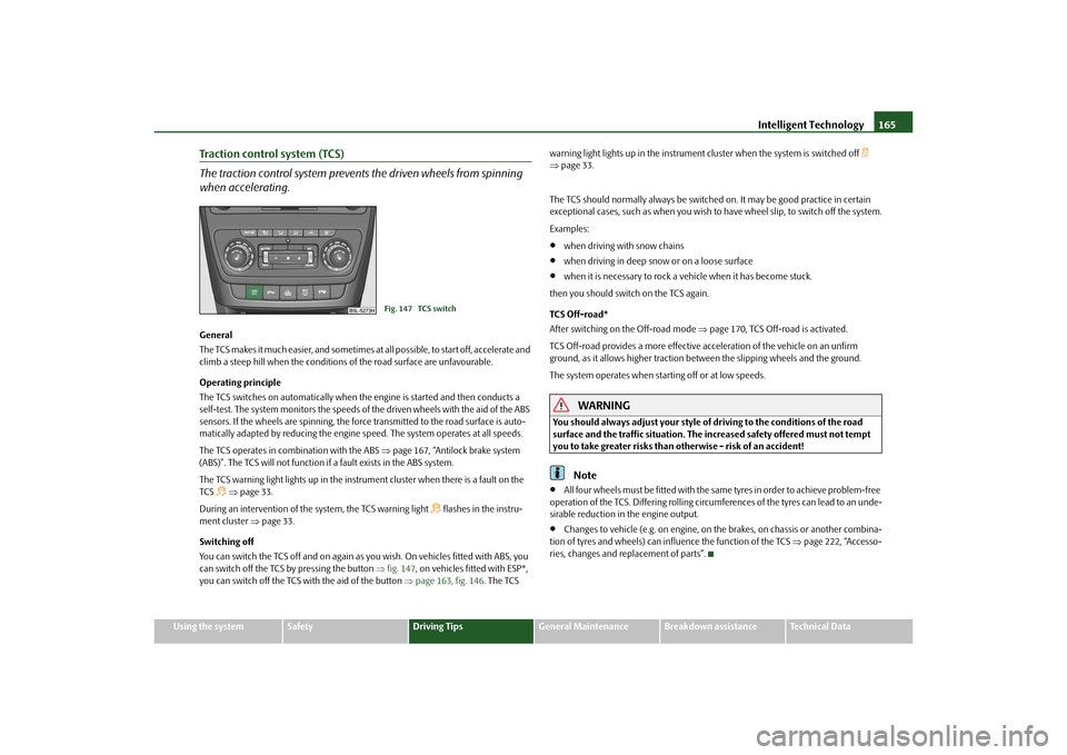
You can switch the TCS off and on again as yo u wish. On vehicles fitted with ABS, you
can switch off the TCS by pressing the button fig. 147 , on vehicles fi tted with ESP*,
you can switch off the TCS wi th the aid of the button page 163, fig. 146 . The TCS warning light lights up in the instrument cluster when the system is switched off
page 33.
The TCS should normally always be switched on. It may be good practice in certain
exceptional cases, such as when you wish to have wheel slip, to switch off the system.
Examples:
when driving with snow chains
when driving in deep snow or on a loose surface
when it is necessary to rock a vehicle when it has become stuck.
then you should switch on the TCS again.
TCS Off-road*
After switching on the Off-road mode page 170, TCS Off-road is activated.
TCS Off-road provides a more effective a cceleration of the vehicle on an unfirm
ground, as it allows higher traction be tween the slipping wheels and the ground.
The system operates when starting off or at low speeds.
WARNING
You should always adjust your style of driving to the conditions of the road
surface and the traffic situation. The increased safety offered must not tempt
you to take greater risks than otherwise - risk of an accident!
Note
All four wheels must be fitted with the same tyres in order to achieve problem-free
operation of the TCS. Differing rolling circumferences of the tyres can lead to an unde-
sirable reduction in the engine output.
Changes to vehicle (e.g. on engine, on the brakes, on chassis or another combina-
tion of tyres and wheels) can influence the function of the TCS page 222, “Accesso-
ries, changes and replacement of parts”.
Fig. 147 TCS switch
s2ug.6.book Page 165 Friday, April 9, 2010 2:24 PM
Page 169 of 271
Intelligent Technology
168
offered by the ABS must not tempt you to take greater risks than otherwise -
risk of an accident!
The normal braking system is still fully functional if there is an ABS fault.
Visit a specialist garage as quickly as poss ible and adjust your style of driving to
take account of the ABS fault in the meantime since you will not know the extent
of the fault and in how far the braking efficiency is affected.Note
A warning light comes on if a fault occurs in the ABS system
page 34.
Changes to vehicle (e.g. on engine, on th e brakes, on chassis or another combina-
tion of tyres and wheels) can in fluence the function of the ABS page 222, “Accesso-
ries, changes and replacement of parts”.
Brake Assist*During a severe brake application (e.g. if a hazard exists), the Brake Assist increases the
braking force and thus makes it possible to rapidly produce the pressure required in
the brake system.
The majority of drivers do apply the brakes in good time in dangerous situations, but
do not depress the brake pedal with sufficient pressure. Consequently, it is not possible
for the vehicle to achieve its maximum deceleration and the vehicle covers a greater
distance than necessary.
The Brake Assist is activated by the very quick operation of the brake pedal. In such
cases, a much greater braking pressure exists than during a normal brake application.
This makes it possible, even with a relative ly low resistance of the brake pedal, to
produce an adequate pressure in the brake system in the shortest possible time, which
is required for maximum deceleration of th e vehicle. You must apply the brake pedal
firmly and hold it in this position in order to achieve the shortest possible braking
distance.
The Brake Assist is able to help you achieve a shorter braking distance in emergency
situations by rapidly producing the pressure required in the brake system. It fully
exploits the attributes of the ABS. After you release the brake pedal, the function of the
Brake Assist is automatically switched off and the brakes operate in the normal way. The Brake Assist is part of the ESP system. If a fault occurs in the ESP, the Brake Assist
function is also not available.
Further information on the ESP page 163.
WARNING
The Brake Assist is also not able to overcome the physical limits of your
vehicle in terms of the braking distance required.
Adapt your speed to the conditions of th e road surface and to the traffic situ-
ation.
The increased safety offered by the Brake Assist must not tempt you to take
a greater safety risk than otherwise.
Uphill Start Assist*The uphill start assist makes it easier to start off on steep hills. The system assists a start
off by holding the brake pressure produced by the brake pedal actuation for approx. 2
seconds after releasing the brake pedal. The driver can therefore move his foot from
the brake pedal to the accelerator pedal and start off on the slope, without having to
actuate the handbrake. The brake pressure drops gradually the more you operate the
accelerator pedal. If the vehicle does not start off within 2 seconds, it starts to roll back.
The uphill start assist is active as of a 3% slope, if the driver door is closed. It is always
active on slopes when in forward or reverse start off. When driving downhill, it is
inactive.Electromechanical power steeringThe power steering enables you to steer the vehicle with less physical force.
With the electromechanical power steering, the steering assist is automatically
adapted to the speed and to the steering angle.
It is still possible to fully steer the vehicle if the power steering fails or if the engine is
not running (vehicle being towed in). The only difference is that greater physical effort
is required.
If there is a fault in the power steering, the warning light
or lights up in the instru-
ment cluster page 31.
WARNING (continued)
s2ug.6.book Page 168 Friday, April 9, 2010 2:24 PM
Page 170 of 271
Intelligent Technology169
Using the system
Safety
Driving Tips
General Maintenance
Breakdown assistance
Technical Data
WARNING
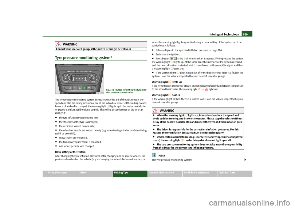
Contact your specialist garage if the power steering is defective.Tyre pressure monitoring system*The tyre pressure monitoring system compares with the aid of the ABS sensors the
speed and also the rolling circumference of the individual wheels. If the rolling circum-
ference of a wheel is changed, the warning light
lights up in the instrument cluster
page 34 and an audible sign al sounds. The rolling circumference of the tyre can
change if:
the tyre inflation pressure is too low,
the structure of the tyre is damaged,
the vehicle is loaded on one side,
the wheels of an axle are loaded heavily (e.g. when towing a trailer or when driving
uphill or downhill),
snow chains are mounted,
the temporary spare wheel is mounted,
one wheel per axle was changed.
Basic setting of the system
After changing the tyre inflation pressures, after changing one or several wheels, the
position of a wheel on the vehicle (e.g. exch anging the wheels between the axles) or when the warning light lights up while drivin
g, a basic setting of the system must be
carried out as follows.
Inflate all tyres to the specified inflation pressure page 216.
Switch on the ignition.
Press button fig. 148 for more than 2 seconds. While pressing the button,
the warning light
lights up. At the same time the memory of the system is erased
and the new calibration is started, which is confirmed with an audible signal and then
the warning light goes out.
If the warning light
does not go out after the basic setting, there is a fault in the
system. Have the vehicle inspected by your nearest specialist garage.
Warning light
lights up
If the tyre inflation pressure of at least one wheel is insufficiently inflated in comparison
to the stored basic va lue, the warning light
lights up.
Warning light
flashes
If the warning light flashes, there is a system fault. Have the vehicle inspected by your
nearest specialist garage.
WARNING
When the warning light
lights up, immediately reduce the speed and
avoid sudden steering and brake manoeuvr es. Please stop the vehicle without
delay at the nearest possible stop and in spect the tyres and their inflation pres-
sures.
The driver is responsible for the correc t tyre inflation pressures. For this
reason, the tyre inflation pressures must be checked regularly.
Under certain circumstances (e.g. sporty style of driving, wintry or unpaved
roads) the warning light
can be delayed or does not light up at all.
The tyre pressure monitoring system do es not take away the responsibility
from the driver for the correct tyre inflation pressure.Note
The tyre pressure monitoring system:
Fig. 148 Button for setting the tyre infla-
tion pressure control value
s2ug.6.book Page 169 Friday, April 9, 2010 2:24 PM
Page 185 of 271
Driving and the Environment
184
Shifting gears correctlyThe gear you must shift into depends on th e terrain. Choosing the correct gear contrib-
utes to safe driving. In partic ular if you do not have much experience driving off-road,
it is always better, before negotiating a difficult stretch of the road, to pause and reflect
on which gear to engage. Your experience will tell you which gear is the best for certain
sections of the terrain.
Basically:
When the gear or the driving stage has been properly selected, it is unnecessary to
slow down the vehicle on a downhill sectio n using the footbrake as in most cases the
engine braking power is sufficient.
Depress the accelerator only as much as is necessary. A too great acceleration may
lead to the wheels spinning and thus results in the loss over the control of the vehicle.
Manual gearbox
If you are driving thro ugh difficult terrain, on no account use the clutch or change
the gear. When the clutch is depressed, th e vehicle may come to a standstill because
of the increased grip of all the tyres of the vehicle (e.g. in the mud, in deep sand or on
a slope). Once the vehicle has come to a stan dstill, it may be difficult or even impos-
sible to start off under these conditions.
When negotiating a steep downhill section or a steep uphill section, always shift
into the 1st or 2nd gear.
On a soft or slippery ground, you must drive at the appropriate speed and you
must select the highest possible gear for this.
Automatic gearbox
Select the selector lever position for normal flat stretches of terrain
page 121.
While in the Tiptronic mode, select the se lector lever position or if you are
driving through mud, sand, water or hilly sections of terrain page 123.
When negotiating a steep downhill section or a steep uphill section, select the
selector lever position while in the Tiptronic mode.
On a soft or slippery ground, you must drive at the appropriate speed and you
must select the highest possible driving stage.
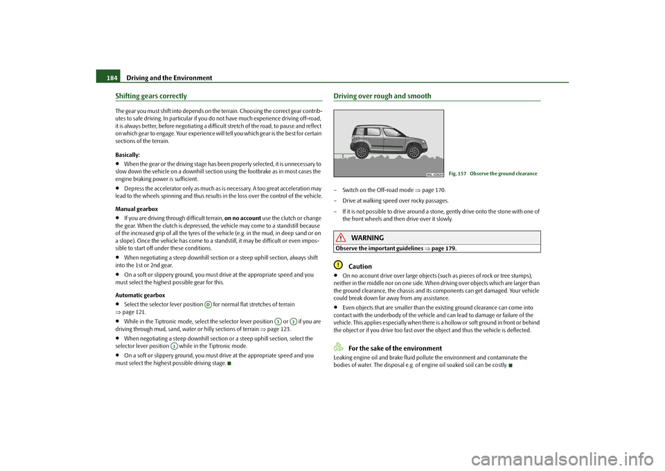
Driving over rough and smooth– Switch on the Off-road mode page 170.
– Drive at walking speed over rocky passages.
– If it is not possible to drive around a stone, gently drive onto the stone with one of the front wheels and then drive over it slowly.
WARNING
Observe the important guidelines page 179.
Caution
On no account drive over large objects (suc h as pieces of rock or tree stumps),
neither in the middle nor on one side. When driving over objects which are larger than
the ground clearance, the chassis and its components can get damaged. Your vehicle
could break down far away from any assistance.
Even objects that are smaller than the existing ground clearance can come into
contact with the underbody of the vehicle an d can lead to damage or failure of the
vehicle. This applies especially when there is a hollow or soft ground in front or behind
the object or if you drive too fast over the object and thus the vehicle is deflected.For the sake of the environment
Leaking engine oil and brake fluid poll ute the environment and contaminate the
bodies of water. The disposal e.g. of engine oil soaked soil can be costly.
AD
A3
A2
A1
Fig. 157 Observe the ground clearance
s2ug.6.book Page 184 Friday, April 9, 2010 2:24 PM
Page 188 of 271
Driving and the Environment187
Using the system
Safety
Driving Tips
General Maintenance
Breakdown assistance
Technical Data
tilt, steer immediat
ely downhill on your trajec tory and lightly depress the
accelerator.
If the vehicle is stationary on a hillside with a too great angle of lateral incli-
nation, avoid sudden and uncontrolled movements in the vehicle. The vehicle
can roll over and then roll down the hillside. This can lead to serious injuries.
If the vehicle is stationary on a hillside with a too great angle of lateral incli-
nation, neither you nor your occupants must exit the vehicle through the doors
facing downhill. This can lead to a shift of the overall centre of gravity. The
vehicle can tilt or roll over and then roll down the hillside. This can lead to
serious injuries. To avoid this, you and your occupants must exit the vehicle
only on the side facing uphill page 186, fig. 158.
When you exit the vehicle, make sure that the door which faces uphill does
not close by its own weight or by carelessness - risk of injury!
Observe the important guidelines page 179.
Driving over rutted roads and troughsYou will always encounter ruts when driv ing on forest roads, through wet meadows
and fields as well as on rutted stretches of terrain.
If the ruts and troughs are on firm and soft ground, you can simply follow the ruts.
Do not drive over ruts and troughs which ar e too deep. If you cannot avoid this, it is
better that you turn back.
Caution
If the ruts or troughs become too deep, the underbody of the vehicle can touch the
ground, which might cause the underbody to get damaged. Therefore, avoid driving in
deep ruts and troughs.Crossing a trenchIf possible, drive through the trench at an acute angle. Make sure when driving through
the trench that the tilt angle is not too steep.
WARNING
Never attempt to drive through a trench if its embankment is too steep. The
vehicle could slip, tilt or roll over - risk of accident!
Caution
If you drive into the trench at a right angle, the front wheels will sink into the trench.
There is also the danger that the underbod y of the vehicle touches the ground and is
damaged. For these reasons (even with four-wheel drive) it is rarely possible to get out
of the trench.Driving in sand and mudYou should therefore always drive at a cons tant speed through sand or mud whenever
possible and at the same time do not shift gears or change the driving stage.
– Switch on the Off-road mode page 170.
– Select a suitable gear or driving stage and maintain the gear or driving stage.
– Keep your vehicle in constant motion and do not stop until you have reached firm
ground.
Never drive too fast, otherwise the wheels may spin and the vehicle can get stuck. If
you feel that the tyres do no longer grip, then turn the steering wheel quickly back and
forth. This leads to an improved adhesion of the front tyres of the vehicle for a short
period of time.
Driving through sand
Do not reduce the tyre inflation pressure. If yo u nevertheless reduce the inflation
pressure, do not forget to re-establish the correct tyre inflation pressure level before
you continue driving. Driving with a reduced tyre inflation pressure increases the risk
that you lose control over your vehicle and that the vehicle rolls over.
Driving through mud
Do not change speed or direction when you drive through the mud. The tyres can lose
their grip in the mud. If the vehicle slides, you must steer in the appropriate direction
in order to regain control over the vehicle.
WARNING (continued)
s2ug.6.book Page 187 Friday, April 9, 2010 2:24 PM
Page 219 of 271
Wheels and Tyres
218
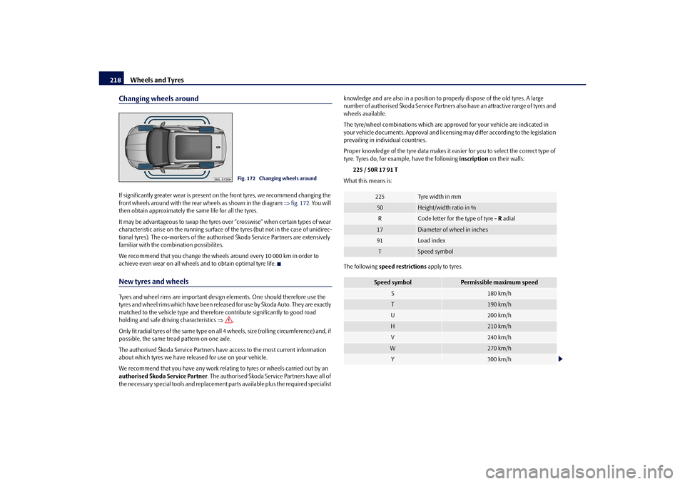
Changing wheels aroundIf significantly greater wear is present on the front tyres, we recommend changing the
front wheels around with the rear wheels as shown in the diagram fig. 172 . You will
then obtain approximately the same life for all the tyres.
It may be advantageous to swap the tyres ov er “crosswise” when certain types of wear
characteristic arise on the running surface of the tyres (but not in the case of unidirec-
tional tyres). The co-workers of the authorised Škoda Service Partners are extensively
familiar with the combination possibilites.
We recommend that you change the wheels around every 10 000 km in order to
achieve even wear on all wheels and to obtain optimal tyre life.New tyres and wheelsTyres and wheel rims are important design elements. One should therefore use the
tyres and wheel rims which have been releas ed for use by Škoda Auto. They are exactly
matched to the vehicle type and therefore contribute significantly to good road
holding and safe driving characteristics .
Only fit radial tyres of the same type on all 4 wheels, size (rolling circumference) and, if
possible, the same tread pattern on one axle.
The authorised Škoda Service Partners have access to the most current information
about which tyres we have released for use on your vehicle.
We recommend that you have any work relati ng to tyres or wheels carried out by an
authorised Škoda Service Partner . The authorised Škoda Service Partners have all of
the necessary special tools and replacement pa rts available plus the required specialist knowledge and are also in a position to pr
operly dispose of the old tyres. A large
number of authorised Škoda Service Partners also have an attractive range of tyres and
wheels available.
The tyre/wheel combinations which are appr oved for your vehicle are indicated in
your vehicle documents. Approval and licens ing may differ according to the legislation
prevailing in indi vidual countries.
Proper knowledge of the tyre data makes it ea sier for you to select the correct type of
tyre. Tyres do, for example, have the following inscription on their walls:
225 / 50R 17 91 T
What this means is:
The following speed restrictions apply to tyres.
Fig. 172 Changing wheels around
225
Tyre wi dt h i n mm
50
Height/width ratio in %
R
Code letter for the type of tyre - R adial
17
Diameter of wheel in inches
91
Load index
T
Speed symbol
Speed symbol
Permissible maximum speed
S
180 km/h
T
190 km/h
U
200 km/h
H
210 km/h
V
240 km/h
W
270 km/h
Y
300 km/h
s2ug.6.book Page 218 Friday, April 9, 2010 2:24 PM
Page 226 of 271
Breakdown assistance225
Using the system
Safety
Driving Tips
General Maintenance
Breakdown assistance
Technical Data
Changing a wheelPreliminary workThe following steps should be carried ou t before actually changing the wheel.
– If it is necessary to change a wheel, park the vehicle as far away as possible from
the traffic flow. The place you choose should be level.
–Have all the occupants get out. While changing a wheel, the occupants of the
vehicle should not stand on the road (e.g. behind a crash barrier).
– Apply the handbrake firmly.
–Engage 1st gear or if your vehicle is fitted with an automatic gearbox, position the
selector lever into position P .
– If a trailer is coupled, uncouple it.
–Take the vehicle tool kit page 223 and the spare wheel* page 224 out of the
luggage compartment.
WARNING
If you find yourself in flowing traffic switch on the hazard warning lights
system and place the warning triangle on the side of the road at the prescribed
distance from your vehicle while observing all national legal provisions. In this
way you are protecting not only yourself but also other road users.
Never start the engine with the vehicle si tting on the raised jack - danger of
suffering injury.Caution
If you have to change a wheel on a slope first block the opposite wheel with a stone or
similar object in order to secure the vehicle from unexpectedly rolling away.
Note
Comply with the national legal regulations.
Changing a wheelAlways change a wheel on a level surface as far as possible.
– Take off the full wheel trim* page 226 or the wheel trim cap page 227 or the
caps page 226.
– In the case of light alloy wheels remove the wheel trim cap page 227.
– First of all slacken the safety wheel bolt * and afterwards the other wheel bolts page 227.
– Jack up the vehicle until the wheel to be changed is clear of the ground
page 227.
– Unscrew the wheel bolts and place them on a clean surface (cloth, paper etc.).
– Take off the wheel.
– Fit on the spare wheel and tighten the wheel bolts slightly.
– Lower the car.
– Tighten the wheel bolts firmly, alternatel y and diagonally using the wheel wrench
(crosswise) and last the safety wheel bolt* page 227.
– Mount the full wheel trim/wheel trim cap or the caps.
Note
All bolts must be clean and must turn easily.
You must never grease or oil the wheel bolts!
When fitting on unidirectiona l tyres, ensure that the tyres rotate in the correct
direction page 216.
Subsequent stepsAfter changing the wheel, you mu st perform the following steps.
– Stow and attach the replaced wheel in the spare wheel well using a special screw
page 224, fig. 175.
– Stow the vehicle tool kit in the space provided.
– Check the tyre pressure on the spare wheel just mounted as soon as possible.
s2ug.6.book Page 225 Friday, April 9, 2010 2:24 PM
Page 227 of 271
Breakdown assistance
226
– Have the tightening torque of the wheel bolts checked with a torque wrench as
soon as possible. Steel and light alloy wh eels must be tightened to a tightening
torque of 120 Nm .
– Change the damaged wheel or consult a specialist garage about possibilities for getting repairs done.
WARNING
It is necessary to observe the guidelines given on page 218 if the vehicle is
subsequently fitted with tyres which are different to those it was fitted with at
the works.
Note
If you find, when changing the wheel, that the wheel bolts are corroded and diffi-
cult to turn, the bolts must be replaced before checking the tightening torque.
Drive cautiously and only at a moderate speed to a workshop where the tightening
torque can be checked.
Full wheel trim*Pulling off– Hook the clamp found in the vehicle tool kit into the reinforced edge of the full
wheel trim.
– Push the wheel key through the clamp, support the wheel key at the tyre and pull off the wheel trim.Installing– First press the full wheel trim onto the wheel at the valve opening provided. Then
press the full wheel trim into the wheel in such a way that its entire circumference
locks correctly in place.
Caution
Use the pressure of your hand, do not knock on the full wheel trim! Heavy knocks
mainly on the points where the full wheel trim has not been inserted into the wheel,
can result in damage to the guide and centering elements of the full wheel trim.
Check for yourself that the safety wheel bolt is located in the hole in the area of the
valve before fitting the full wheel trim onto a steel wheel which is attached with a safety
wheel bolt page 228.
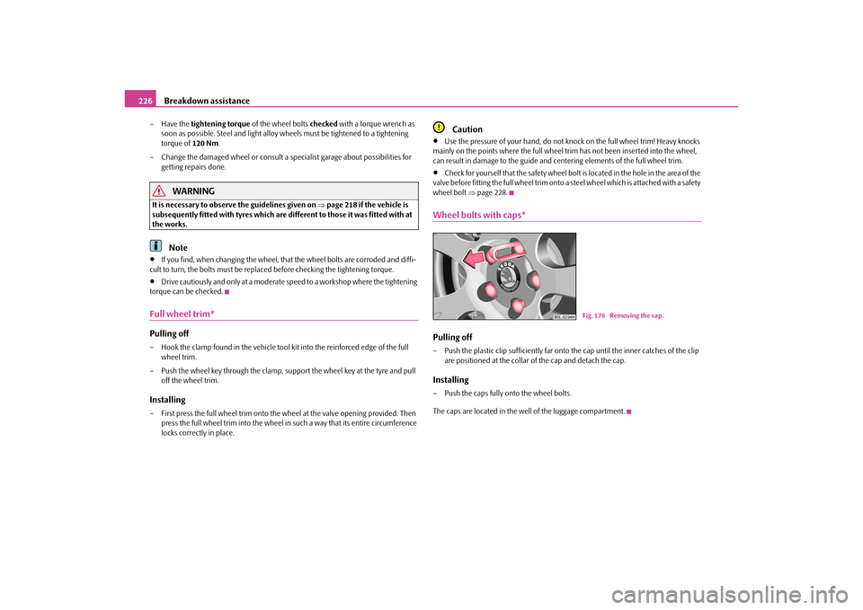
Wheel bolts with caps*Pulling off– Push the plastic clip sufficie ntly far onto the cap until the inner catches of the clip
are positioned at the collar of the cap and detach the cap.Installing– Push the caps fully onto the wheel bolts.
The caps are located in the well of the luggage compartment.
Fig. 176 Removing the cap.
s2ug.6.book Page 226 Friday, April 9, 2010 2:24 PM