steering wheel SKODA YETI 2010 1.G / 5L User Guide
[x] Cancel search | Manufacturer: SKODA, Model Year: 2010, Model line: YETI, Model: SKODA YETI 2010 1.G / 5LPages: 271, PDF Size: 14.71 MB
Page 55 of 271
Lights and Visibility
54
Deactivating the function daylight driving lights
– Pull the turn signal light lever towards the steering wheel up to 3 seconds after switching on the ignition and at the same time, slide it to the bottom and hold it in
this position for at least 3 seconds.Activating the function daylight driving lights– Pull the turn signal light lever towards the steering wheel up to 3 seconds after switching on the ignition and at the same time, slide it to the top and hold it in this
position for at least 3 seconds.
In some countries, the national legal provisions require that the rear parking lights
come on together with the bulbs for daylight driving lights when activating the function
daylight driving lights.
On vehicles which are fitted with bulbs for daylight driving lights in the fog lights, the
parking lights do not come on when activa ting the function daylight driving lights.
When the daylight driving lights are switched on, the lighting of the instrument cluster
is switched on as well.
On vehicles fitted with an information displa y*, you can also activate or deactivate in
the menu the function da ylight driving lights:
Setup
Lights & Vision (Lights & Vision)
Automatic driving lamp control*
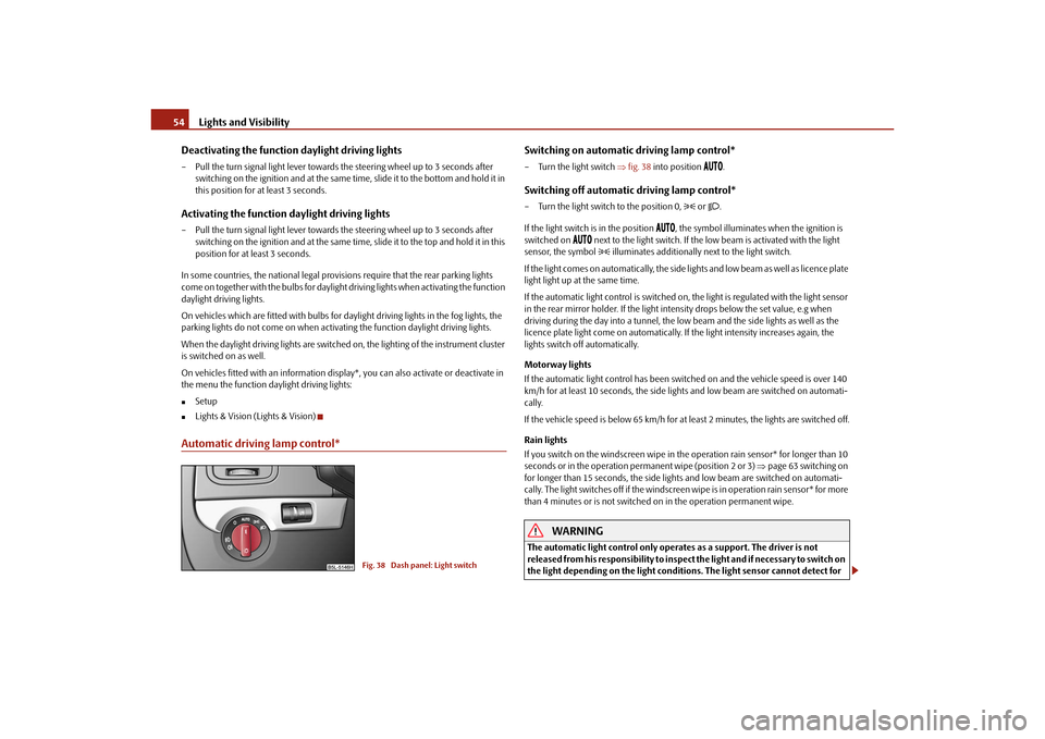
Switching on automatic driving lamp control*– Turn the light switch fig. 38 into position
.
Switching off automatic driving lamp control*– Turn the light switch to the position 0,
or .
If the light switch is in the position
, the symbol illuminates when the ignition is
switched on
next to the light switch. If the low beam is activated with the light
sensor, the symbol illuminates additionally next to the light switch.
If the light comes on automatically, the side lights and low beam as well as licence plate
light light up at the same time.
If the automatic light control is switched on, the light is regulated with the light sensor
in the rear mirror holder. If the light intensity drops below the set value, e.g when
driving during the day into a tunnel, the lo w beam and the side lights as well as the
licence plate light come on automatically. If the light intensity increases again, the
lights switch off automatically.
Motorway lights
If the automatic light control has been swit ched on and the vehicle speed is over 140
km/h for at least 10 seconds, the side ligh ts and low beam are switched on automati-
cally.
If the vehicle speed is below 65 km/h for at least 2 minutes, the lights are switched off.
Rain lights
If you switch on the windscreen wipe in th e operation rain sensor* for longer than 10
seconds or in the operation perm anent wipe (position 2 or 3) page 63 switching on
for longer than 15 seconds, the side ligh ts and low beam are switched on automati-
cally. The light switches off if the windscreen wipe is in operation rain sensor* for more
than 4 minutes or is not switched on in the operation permanent wipe.
WARNING
The automatic light control only operat es as a support. The driver is not
released from his responsibility to inspect the light and if necessary to switch on
the light depending on the light conditions. The light sensor cannot detect for
Fig. 38 Dash panel: Light switch
s2ug.6.book Page 54 Friday, April 9, 2010 2:24 PM
Page 58 of 271
Lights and Visibility57
Using the system
Safety
Driving Tips
General Maintenance
Breakdown assistance
Technical Data
The warning light
lights up in the instrument cluste
r when the fog lights are switched
on page 28.
Fog lights with turning light “CORNER”* function
The fog lights with the function “COR NER” are designed for a better illu-
mination of the surrounding area near the vehicle when corning,
parking etc.The fog lights with the function “CORNER” ar e adjusted according to the steering angle
or after switching on the turn signal light
8) in the following circumstances:
the vehicle is stationary and the engine is running or it moves with a speed of
maximum 40 km/h;
the daylight driving lights are not switched on;
the low beam is switched on or th e light switch is in the position
and the
intensity of the ambient light causes the low beam to be switched on;
the fog lights are not switched on;
no reverse gear is engaged.Note
If you engage the reverse gear during the active function “CORNER”, both fog lights
illuminate.Rear fog light
Switching on the rear fog light– First of all turn the light switch into position
or page 56, fig. 39 .
– Pull the switch into position .
The warning light
lights up in the instrument cluster when the rear fog light is
switched on page 28. Only the rear fog light of the trailer lights
up automatically when you are towing a trailer
using a factory-fitted towing device from Škoda original accessories which is
fitted with the rear fog light.
The rear fog light is located in the rear light array on the driver's side.
Caution
The rear fog light should only be switched on if visibility is particularly poor (conform
with any varying legal provisions) to avoi d dazzling vehicles behind your vehicle.Instrument lighting*
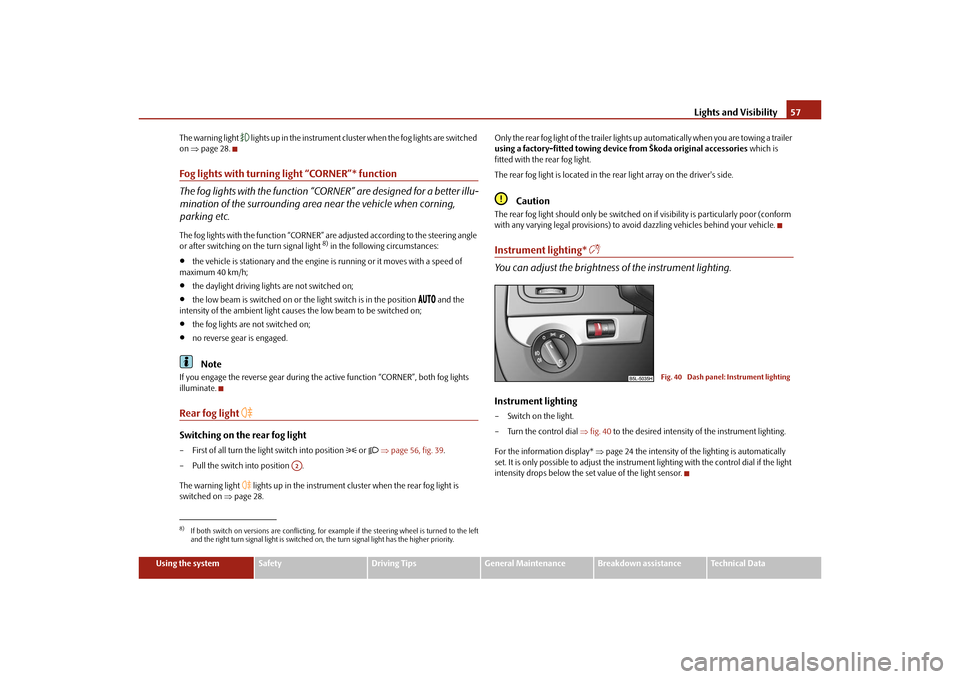
You can adjust the brightness of the instrument lighting.Instrument lighting– Switch on the light.
– Turn the control dial fig. 40 to the desired intensity of the instrument lighting.
For the information display* page 24 the intensity of the lighting is automatically
set. It is only possible to adjust the instrume nt lighting with the control dial if the light
intensity drops below the set value of the light sensor.
8)If both switch on versions are conflicting, for ex ample if the steering wheel is turned to the left
and the right turn signal light is switched on, the turn signal light has the higher priority.
A2
Fig. 40 Dash panel: Instrument lighting
s2ug.6.book Page 57 Friday, April 9, 2010 2:24 PM
Page 60 of 271
Lights and Visibility59
Using the system
Safety
Driving Tips
General Maintenance
Breakdown assistance
Technical Data
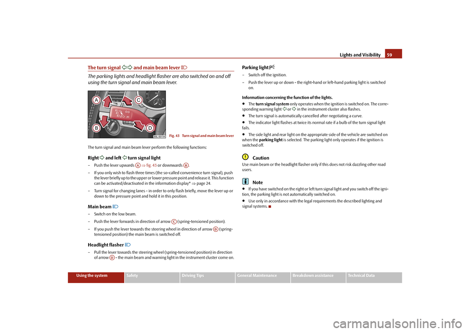
The turn signal
and main beam lever
The parking lights and headlight flas her are also switched on and off
using the turn signal and main beam lever.The turn signal and main beam le ver perform the following functions:Right
and left
turn signal light
– Push the lever upwards fig. 43 or downwards .
– If you only wish to flash three times (the so-called convenience turn signal), push
the lever briefly up to the upper or lower pr essure point and release it. This function
can be activated/deactivated in the information display* page 24.
– Turn signal for changing lanes - in order to only flash briefly, move the lever up or
down to the pressure point and hold it in this position.Main beam
– Switch on the low beam.
– Push the lever forwards in direction of arrow (spring-tensioned position).
– If you push the lever towards the steering wheel in direction of arrow (spring-
tensioned position) the main beam is switched off.Headlight flasher
– Pull the lever towards the steering wheel (spring-tensioned position) in direction
of arrow - the main beam and warning light in the instrument cluster come on.
Parking light
– Switch off the ignition.
– Push the lever up or down - the right-hand or left-hand parking light is switched
on.
Information concerning the function of the lights.
The turn signal system only operates when the ignition is switched on. The corre-
sponding warning light
or in the instrument cluster also flashes.
The turn signal is automatically cancelled after negotiating a curve.
The indicator light flashes at twice its normal rate if a bulb of the turn signal light
fails.
The side light and rear light on the appropriate side of the vehicle are switched on
when the parking light is selected. The parking light only operates if the ignition is
switched off.Caution
Use main beam or the headlight flasher only if this does not risk dazzling other road
users.
Note
If you have switched on the right or left turn signal light and you switch off the igni-
tion, the parking light is not automatically switched on.
Use only in accordance with the legal requirements the described lighting and
signal systems.
Fig. 43 Turn signal and main beam lever
AA
AB
AC
AD
AD
s2ug.6.book Page 59 Friday, April 9, 2010 2:24 PM
Page 64 of 271
Lights and Visibility63
Using the system
Safety
Driving Tips
General Maintenance
Breakdown assistance
Technical Data
Windshield wiper and wash systemWindshield wiper
You can operate the windscreen wipers and automatic wipe/wash
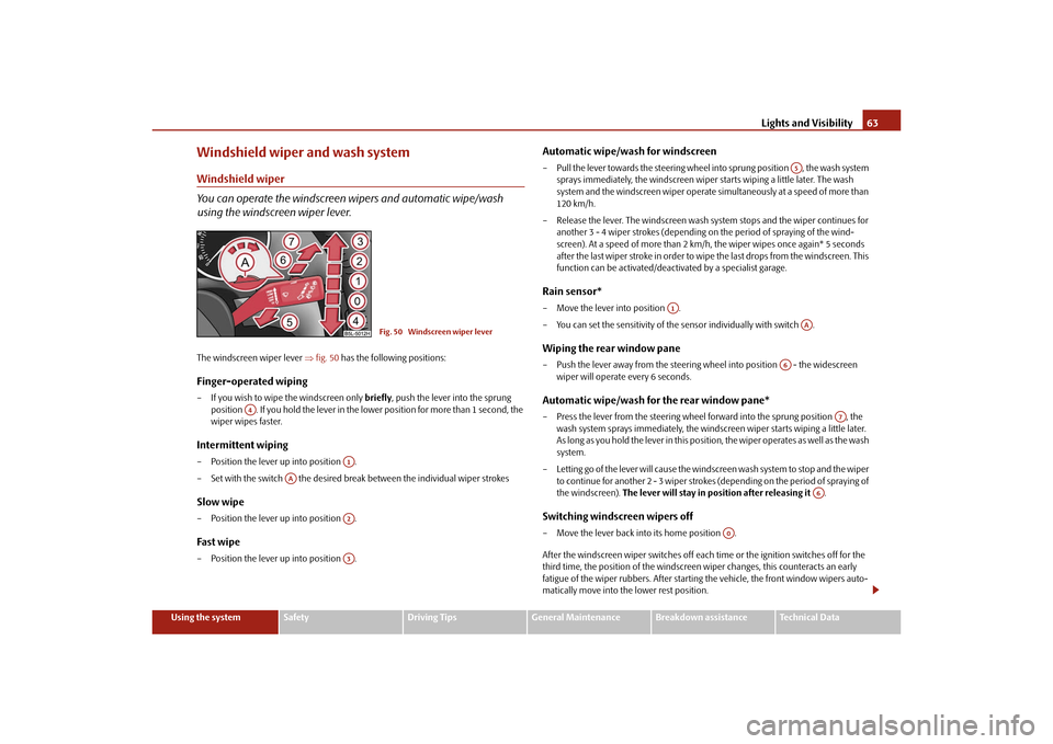
using the windscreen wiper lever.The windscreen wiper lever fig. 50 has the following positions:Finger-operated wiping– If you wish to wipe the windscreen only briefly, push the lever into the sprung
position . If you hold the lever in the lo wer position for more than 1 second, the
wiper wipes faster.Intermittent wiping– Position the lever up into position .
– Set with the switch the desired brea k between the individual wiper strokesSlow wipe– Position the lever up into position .Fast wipe– Position the lever up into position .
Automatic wipe/wash for windscreen– Pull the lever towards the steering wheel into sprung position , the wash system
sprays immediately, the windscreen wiper starts wiping a little later. The wash
system and the windscreen wiper operate simultaneously at a speed of more than
120 km/h.
– Release the lever. The windscreen wash system stops and the wiper continues for another 3 - 4 wiper strokes (depending on the period of spraying of the wind-
screen). At a speed of more than 2 km/h, the wiper wipes once again* 5 seconds
after the last wiper stroke in order to wipe the last drops from the windscreen. This
function can be activated/deacti vated by a specialist garage.Rain sensor*– Move the lever into position .
– You can set the sensitivity of the sensor individually with switch .Wiping the rear window pane– Push the lever away from the steering wheel into position - the widescreen
wiper will operate every 6 seconds.Automatic wipe/wash for the rear window pane*– Press the lever from the steering wheel forward into the sprung position , the wash system sprays immediately, the windscreen wiper starts wiping a little later.
A s l o n g a s y o u h o l d t h e l e v e r i n t h i s p o s i t i o n, th e w i p e r o p e ra t e s a s w e l l a s t h e w a s h
system.
– Letting go of the lever will cause the windscreen wash system to stop and the wiper to continue for another 2 - 3 wiper strokes (depending on the period of spraying of
the windscreen). The lever will stay in position after releasing it .Switching windscreen wipers off– Move the lever back into its home position .
After the windscreen wiper switches off each time or the ignition switches off for the
third time, the position of the windscreen wiper changes, this counteracts an early
fatigue of the wiper rubbers. After starting the vehicle, the front window wipers auto-
matically move into the lower rest position.
Fig. 50 Windscreen wiper lever
A4
A1
AA
A2A3
A5
A1
AA
A6
A7
A6
A0
s2ug.6.book Page 63 Friday, April 9, 2010 2:24 PM
Page 70 of 271
Seats and Stowage69
Using the system
Safety
Driving Tips
General Maintenance
Breakdown assistance
Technical Data
Seats and StowageFront seatsBasic informationThe front seats have a wide range of differ ent settings and can thus be matched to the
physical characteristics of the driver and front passenger. Correct adjustment of the
seats is particularly important for:
safely and quickly reaching the controls;
a relaxed, fatigue-free body position;
achieving the maximum protection offered by the seat belts and the airbag
system.
WARNING
Never transport more occupants than the maximum seating in the vehicle.
Each occupant must correctly fasten the seat belt belonging to the seat.
Children must be fastened page 156, “Transporting children safely” with a
suitable restraint system.
The front seats and the head restraints must always be adjusted to match
the body size of the seat occupant as well as the seat belts must always be
correctly fastened in order to provide an optimal protection for you and your
occupants.
Always keep your feet in the footwell when the vehicle is being driven -
never place your feet on the instrument panel, out of the window or on the
surfaces of the seats. This is particular ly important for the front seat passenger.
You will be exposed to increased risk of injury if it becomes necessary to apply
the brake or in the event of an accident. If an airbag is deployed, you may suffer
fatal injuries when adopting an incorrect seated position!
It is important for the driver and front passenger to maintain a distance of at
least 25 cm from the steering wheel or dash panel. Not maintaining this
minimum distance will mean that the airbag system will not be able to properly
protect you - hazard! The front seats and the head restraints must always also
be correctly adjusted to match the body size of the occupant.
Ensure that there are no objects in the footwell as any objects may get
behind the pedals during a driving or braking manoeuvre. You would then no
longer be able to operate the clutch, to brake or accelerate.
Do not transport any objects on the front passenger seat except those
provided for this purpose (e.g. child safety seat) - risk of accident!
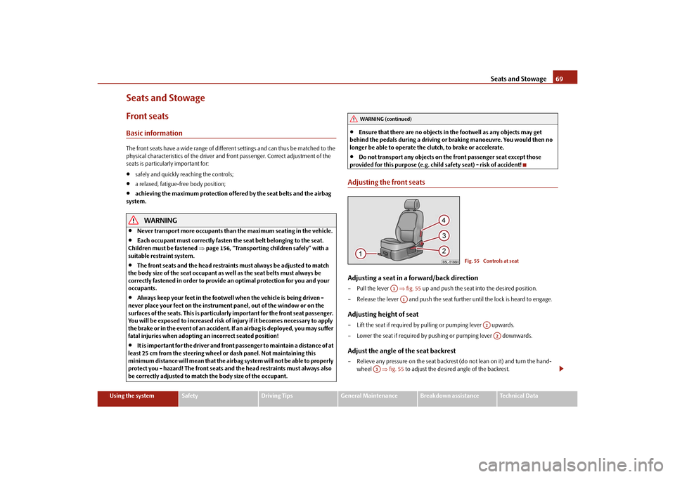
Adjusting the front seatsAdjusting a seat in a forward/back direction–Pull the lever fig. 55 up and push the seat into the desired position.
– Release the lever and push the seat further until the lock is heard to engage.Adjusting height of seat– Lift the seat if required by pulling or pumping lever upwards.
– Lower the seat if required by pushing or pumping lever downwards.Adjust the angle of the seat backrest– Relieve any pressure on the seat backrest (do not lean on it) and turn the hand- wheel fig. 55 to adjust the desired angle of the backrest.
WARNING (continued)
Fig. 55 Controls at seat
A1A1
A2A2
A3
s2ug.6.book Page 69 Friday, April 9, 2010 2:24 PM
Page 71 of 271
Seats and Stowage
70
Adjusting lumbar support*
– Pull on the lever until you have set th e most comfortable curvature of the seat
upholstery in the area of your spine.
The driver's seat should be adjusted in such a way that the pedals can be fully pressed
to the floor with slightly bent legs.
The seat backrest on the driver's seat should be adjusted in such a way that the upper
point of the steering wheel can be easi ly reached with slightly bent arms.
WARNING
Only adjust the driver seat when the vehicle is stationary - risk of injury!
Take care when adjusting the seat! Adjusting the seat without care can lead
to bruises or injuries.
The seat backrests must not be angled too far back when driving otherwise
this will affect proper operation of the se at belts and of the airbag system - risk
of injury!
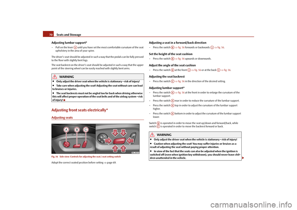
Adjusting front seats electrically*Adjusting seatsFig. 56 Side view: Controls for adju sting the seat / seat setting switchAdopt the correct seated position before setting page 69.
Adjusting a seat in a forward/back direction– Press the switch fig. 56 forwards or backwards fig. 56 .Set the height of the seat cushion– Press the switch fig. 56 upwards or downwards.Adjust the angle of the seat cushion– Press the switch at the front fig. 56 or at the back fig. 56 .Adjusting the seat backrest– Press the switch fig. 56 in the direction of the desired setting.Adjusting lumbar support*– Press the switch fig. 56 at the front in order to enlarge the curvature of the
lumbar support.
– Press the switch rear in order to reduce the curvature of the lumbar support.
– Press the switch top in order to adjust the curvature of the lumbar support higher.
– Press the switch bottom in order to adjust the curvature of the lumbar support lower.
Switch is operated in order to move the seat up/down and forward/back, while
switch is operated in order to move the backrest forward or back.
WARNING
Only adjust the driver seat when the ve hicle is stationary - risk of injury!
Caution when adjusting the seat! You may suffer injuries or bruises as a
result of adjusting the seat without paying proper attention.
In view of the fact that the seats can also be adjusted when the ignition is
switched off (even when ignition key withdrawn), you should never leave chil-
dren unattended in the vehicle.
A4
AB
A1
ABAB
A2
A3
ACAAAAAAAA
ABAC
s2ug.6.book Page 70 Friday, April 9, 2010 2:24 PM
Page 109 of 271
Starting-off and Driving
108
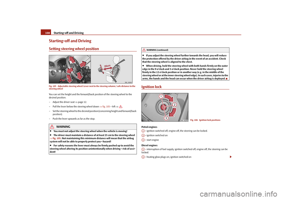
Starting-off and DrivingSetting steering wheel positionFig. 105 Adjustable steering wheel: Lever next to the steering column / safe distance to the
steering wheelYou can set the height and the forward/back position of the steering wheel to the
desired position.
– Adjust the driver seat page 12.
– Pull the lever below the steering wheel down fig. 105 - left .
– Set the steering wheel to the desired position (concerning height and forward/back position).
– Push the lever upwards as far as the stop.
WARNING
You must not adjust the steering wheel when the vehicle is moving!
The driver must maintain a distance of at least 25 cm to the steering wheel
fig. 105 . Not maintaining this minimum dist ance will mean that the airbag
system will not be able to properly protect you - hazard!
For safety reasons the lever must always be firmly pushed up to avoid the
steering wheel altering its po sition unintentionally when driving - risk of acci-
dent!
If you adjust the steering wheel furthe r towards the head, you will reduce
the protection offered by the driver airbag in the event of an accident. Check
that the steering wheel is aligned to the chest.
When driving, hold the steering wheel with both hands firmly on the outer
edge in the 9 o'clock and 3 o'clock position. Never hold the steering wheel
firmly in the 12 o'clock position or in another way (e.g. in the middle of the
steering wheel or at the inne r steering wheel edge). In such cases, injuries to the
arms, the hands and the head can occur when the driver airbag is deployed.
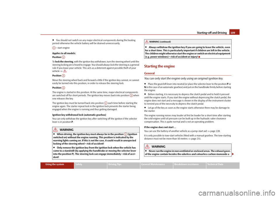
Ignition lockPetrol engines
- ignition switched off, engine off, the steering can be locked.
- ignition switched on
- start engine
Diesel engines - interruption of fuel supply, ignition swit ched off, engine off, the steering can be
locked.
- heating glow plugs on, ignition switched on
WARNING (continued)
Fig. 106 Ignition lock positions
A1A2A3A1A2
s2ug.6.book Page 108 Friday, April 9, 2010 2:24 PM
Page 110 of 271
Starting-off and Driving109
Using the system
Safety
Driving Tips
General Maintenance
Breakdown assistance
Technical Data
You should not switch on any major elec trical components during the heating
period otherwise the vehicle battery will be drained unnecessarily.
- start engine
Applies to all models:
Position
To lock the steering , with the ignition key withdrawn, turn the steering wheel until the
steering locking pin is heard to engage. You should always lock the steering as a general
rule if you leave your vehicle. This acts as a deterrent against possible theft of your
vehicle .
Position
Move the steering wheel back and forward a little if the ignition key cannot, or cannot
easily be turned into this position, in order to release the steering lock.
Position
The engine is started in this position. At the same time, major electrical components
are switched off for short periods. The ignition key moves back into position when
one releases the key.
The ignition key must be turned back into position each time before starting the
engine again. The starter repeat lock in th e ignition lock prevents the starter being
engaged when the engine is r unning and thus getting damaged.
Ignition key withdrawal lock (automatic gearbox)
You can only withdraw the ignition key after switching off the ignition if the selector
lever is in position P.
WARNING
When driving, the ignition key must always be in the position (ignition
switched on) without the engine running. This position is indicated by the
warning lights coming on. If this is not the case, it could result in unexpected
locking of the steering wh eel - risk of accident!
Only remove the ignition key from the ignition lock when the vehicle has
come to a standstill (by applying the handbrake or moving the selector lever
into the position P). The steering lock can engage imme diately - risk of acci-
dent!
Always withdraw the ignition key if you are going to leave the vehicle, even
for a short time. This is particularly important if children are left in the vehicle.
The children might otherwise start the engi ne or switch on electrical equipment
(e.g. power windows) - risk of accident or injury!
Starting the engineGeneral
You can only start the engine only using an original ignition key.
Place the gearshift lever into neutral (or place the selector lever to the position P or
N in the case of an automatic gearbox) and put on the handbrake firmly before starting
the engine.
Before starting, it is necessary to depres s the clutch pedal and to hold it pressed
until the engine starts. If you start the engi ne without depressing the clutch pedal, the
engine does not start and a message is show n in the display of the instrument cluster
to remind you of th e necessity to depress the clutch pedal.
Let go of the key as soon as the engine starts otherwise there may be damage to
the starter.
The engine running noises may louder at first be louder for a short time after starting
the cold engine until oil pressure can be built up in the hydraulic valve clearance
compensation. This is quite normal and is not an operating problem.
If the engine does not start ...
You can use the battery of anothe r vehicle as a jump-start aid page 228.
It is only possible to tow-start vehicles fitt ed with a manual gearbox. The tow-starting
distance must not be more than 50 metres page 231.
WARNING
Never run the engine in non ventilated or enclosed areas. The exhaust gases
of the engine contain besides the odorless and colourless carbon monoxide a
A3
A1A2A3
A2
A1
A2
WARNING (continued)
s2ug.6.book Page 109 Friday, April 9, 2010 2:24 PM
Page 115 of 271
Starting-off and Driving
114
set so that the play function volume decr eases when activating the parking aid, see
Owner's Manual radio* or na vigation system*. This improves the audibility of the
parking aid.
Activating
The parking aid is activated when the reverse gear is engaged and the ignition is
turned on or by pressing the button page 113, fig. 110 - the symbol lights up in
the button. The activation is confirmed by a brief acknowledgement signal.
Deactivating
The parking aid is deactivated after pressing the button° page 113, fig. 110 or at
a speed of more than 10 km/h - the symbol
in the button is no longer illuminated.
WARNING
The parking aid is not a substitute for the driver paying proper attention and
it is always the driver's responsibility to take care when reversing the vehicle or
carrying out similar manoeuvres.
You should therefore satisfy yourself, befo re reversing, that there is no small
obstacle, such as a rock, thin post, trailer drawbar etc., in front or behind your
vehicle. Such an obstacle might not be within the range detected by the sensors.
Under certain circumstances, surfaces of certain objects and types of
clothing cannot reflect the signal of the parking aid. Thus, these objects or
people who wear such clothing are not recognised by the sensors of the parking
aid.Note
Only the front parking aid operates if yo u are towing a trailer (applies only to
models which feature a factory-fitted towing device*).
If a warning signal sounds for about 3 seco nds after activating the system and there
is no obstacle close to your vehicle, this indicates a system fault. The fault is confirmed
additionally when the symbol flashes in the button page 113, fig. 110 . Have the
fault rectified by a specialist workshop.
The sensors must be kept clean and free of ice to enable the parking aid to operate
properly.
If the parking aid is activated and the sele ctor lever of the automatic gearbox is in
the position , warning signal indicates inte rruption (vehicle can no longer move).
Park Assist*Description and important informationThe park assist assists you when parking in a suitable parallel parking space between
two vehicles or behind a vehicle.
The park assist automatically searches for suitable parking spaces after switching on
the ignition and when driving up to 30 km/h.
During the parking procedure the park assist only takes over the steering movements,
the pedals continue to be operated by the driver.
Function of the system is based on:
Length and depth measurement of the parking spaces when driving
Evaluation of the size of the parking space
Definition of the correct position of the vehicle for parking
Calculating the line on which the vehicle drives backwards into the parking space
Actuation of the steering force assistance, automatic spinning of the wheels of the
front axle when parking.
WARNING
The park assist does not take away th e responsability from the driver when
parking.
Pay particular attention to small children and animals as they would not be
recognised by the sensors of the parking aid.
Under certain circumstances, surfaces of certain objects and types of
clothing cannot reflect the signal of the park assist or the parking aid. Thus,
these objects or people who wear such clothing are not recognised by the
sensors of the parking aid.
AP
s2ug.6.book Page 114 Friday, April 9, 2010 2:24 PM
Page 117 of 271
Starting-off and Driving
116Note
If the park assist is switched on, a yellow warning light lights up in the button.
The search for suitable parking spaces is automatic after switching on the ignition
at speeds of more than 30 km/h. Searching for a parking space is performed at the
same time on the driver and front passenger side.
If the sensors find a suitable parking space, they store its parameters until another
suitable parking space has been found or until a distance of 10 m had been driven after
finding the parking space. This is why it is possible to switch on the park assist after
driving past the parking space, the information on whether this parking space is suit-
able for parking appears in the information display*.
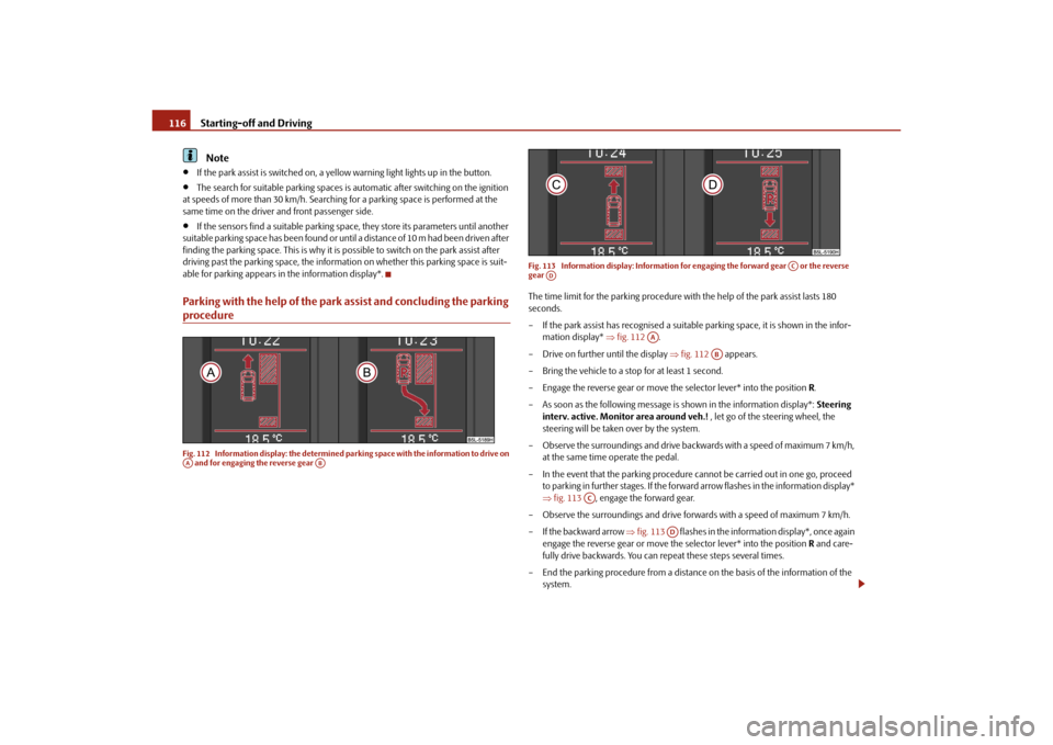
Parking with the help of the park assist and concluding the parking procedureFig. 112 Information display: the determined pa rking space with the information to drive on
and for engaging the reverse gear Fig. 113 Information display: Information fo
r engaging the forward gear or the reverse
gear
The time limit for the parking procedure with the help of the park assist lasts 180
seconds.
– If the park assist has recognised a suitable parking space, it is shown in the infor-
mation display* fig. 112 .
– Drive on further until the display fig. 112 appears.
– Bring the vehicle to a stop for at least 1 second.
– Engage the reverse gear or move the selector lever* into the position R.
– As soon as the following message is shown in the information display*: Steering
interv. active. Monitor area around veh.! , let go of the steering wheel, the
steering will be taken over by the system.
– Observe the surroundings and drive back wards with a speed of maximum 7 km/h,
at the same time operate the pedal.
– In the event that the parking procedure cannot be carried out in one go, proceed to parking in further stages. If the forward arrow flashes in the information display*
fig. 113 , engage the forward gear.
– Observe the surroundings and drive forw ards with a speed of maximum 7 km/h.
– If the backward arrow fig. 113 flashes in the information display*, once again
engage the reverse gear or move the selector lever* into the position R and care-
fully drive backwards. You can repeat these steps several times.
– End the parking procedure from a distance on the basis of the information of the
system.
AA
AB
AC
AD
AA
AB
AC
AD
s2ug.6.book Page 116 Friday, April 9, 2010 2:24 PM