ECU SKODA YETI 2014 1.G / 5L Owner's Guide
[x] Cancel search | Manufacturer: SKODA, Model Year: 2014, Model line: YETI, Model: SKODA YETI 2014 1.G / 5LPages: 248, PDF Size: 29.49 MB
Page 102 of 248
Removing›Grasp the storage compartment on the two upper corners.›
Press the upper corners inwards and release the storage compartment by
pulling upwards.
›
Remove the storage compartment by pulling towards you.
CAUTION
The storage compartment is designed for storing small objects with a maxi-
mum total weight of 8 kg.
Note
The flexible storage compartment cannot be installed on vehicles with the var-
iable loading floor » page 102.
Floor covering on both sides
Read and observe
and on page 96 first.
You can fit a double-sided floor covering in the luggage compartment.
One side of the double-sided floor covering is made of fabric, the other side is
washable (easy to maintain).
The washable side is used to transport wet or dirty items.
Note
For easier turning of the covering, use the loop attached.
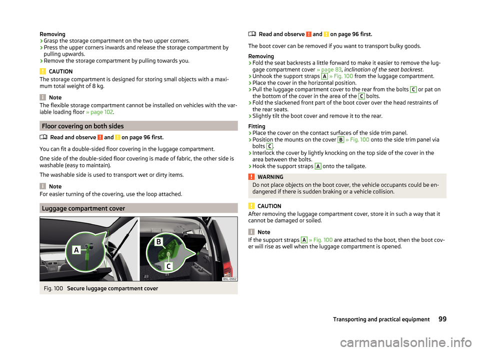
Luggage compartment cover
Fig. 100
Secure luggage compartment cover
Read and observe and on page 96 first.
The boot cover can be removed if you want to transport bulky goods.
Removing
›
Fold the seat backrests a little forward to make it easier to remove the lug-
gage compartment cover » page 83, inclination of the seat backrest .
›
Unhook the support straps
A
» Fig. 100 from the luggage compartment.
›
Place the cover in the horizontal position.
›
Pull the luggage compartment cover to the rear from the bolts
C
or pat on
the bottom of the cover in the area of the
C
bolts.
›
Fold the slackened front part of the boot cover over the head restraints of
the rear seats.
›
Slightly tilt the boot cover and remove it to the rear.
Fitting
›
Place the cover on the contact surfaces of the side trim panel.
›
Position the mounts on the cover
B
» Fig. 100 onto the side trim panel via
bolts
C
.
›
Interlock the cover by lightly knocking on the top side of the cover in the
area between the bolts.
›
Hook the support straps
A
onto the tailgate.
WARNINGDo not place objects on the boot cover, the vehicle occupants could be en-
dangered if there is sudden braking or a vehicle collision.
CAUTION
After removing the luggage compartment cover, store it in such a way that it
cannot be damaged or soiled.
Note
If the support straps A » Fig. 100 are attached to the boot, then the boot cov-
er will rise as well when the luggage compartment is opened.99Transporting and practical equipment
Page 105 of 248
Class N1 vehiclesRead and observe
and on page 96 first.
On class N1 vehicles, which are not fitted with a protective grille, a lashing set
which complies with the standard EN 12195 (1 - 4) must be used for fastening
the load.
Proper functioning of the electrical installation is essential for safe vehicle op-
eration. It is important to ensure that the electrical installation is not damaged
during the adjustment process or when the storage area is being loaded and
unloaded.
Variable loading floor in the luggage compartment (Estate)
Introduction
This chapter contains information on the following subjects:
Removing and inserting the variable loading floor
102
Securing the loading floor in the raised position
102
Removing and refitting carrier rails
103
Using the variable loading floor with a spare wheel
103
The variable loading floor makes it easier to handle bulky goods and creates an
even boot floor when the rear seat backrests are folded forward.
CAUTION
The maximum permissible load of the variable loading floor is 75 kg.
Note
The room under the variable loading floor can be used to stow objects.Removing and inserting the variable loading floorFig. 105
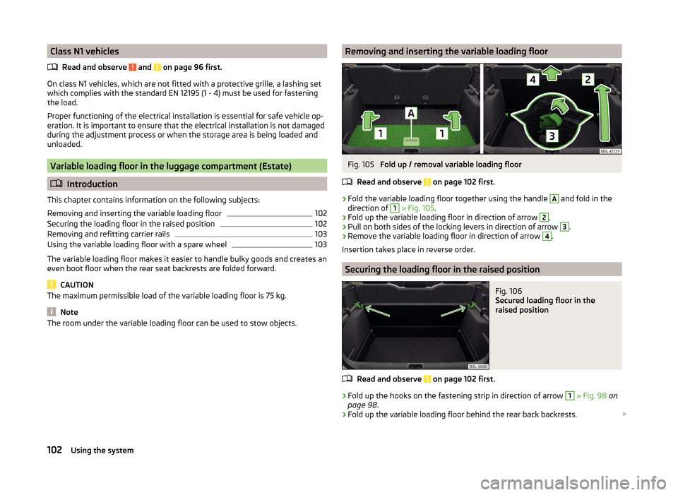
Fold up / removal variable loading floor
Read and observe
on page 102 first.
›
Fold the variable loading floor together using the handle
A
and fold in the
direction of
1
» Fig. 105 .
›
Fold up the variable loading floor in direction of arrow
2
.
›
Pull on both sides of the locking levers in direction of arrow
3
.
›
Remove the variable loading floor in direction of arrow
4
.
Insertion takes place in reverse order.
Securing the loading floor in the raised position
Fig. 106
Secured loading floor in the
raised position
Read and observe on page 102 first.
›
Fold up the hooks on the fastening strip in direction of arrow
1
» Fig. 98 on
page 98 .
›
Fold up the variable loading floor behind the rear back backrests.
102Using the system
Page 106 of 248
›Fold down the hooks in direction of arrow 3
» Fig. 98 on page 98 as far as
the stop.›
Support the variable loading floor on the hooks folded downwards » Fig. 106.
Removing and refitting carrier rails
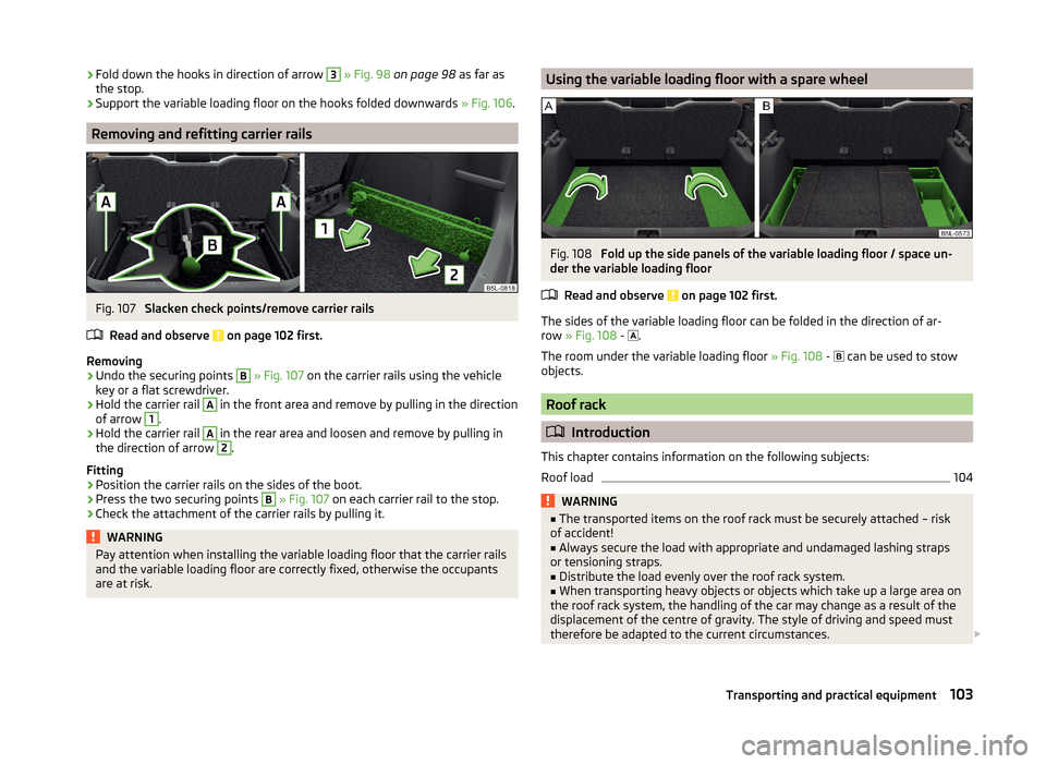
Fig. 107
Slacken check points/remove carrier rails
Read and observe
on page 102 first.
Removing
›
Undo the securing points
B
» Fig. 107 on the carrier rails using the vehicle
key or a flat screwdriver.
›
Hold the carrier rail
A
in the front area and remove by pulling in the direction
of arrow
1
.
›
Hold the carrier rail
A
in the rear area and loosen and remove by pulling in
the direction of arrow
2
.
Fitting
›
Position the carrier rails on the sides of the boot.
›
Press the two securing points
B
» Fig. 107 on each carrier rail to the stop.
›
Check the attachment of the carrier rails by pulling it.
WARNINGPay attention when installing the variable loading floor that the carrier rails
and the variable loading floor are correctly fixed, otherwise the occupants
are at risk.Using the variable loading floor with a spare wheelFig. 108
Fold up the side panels of the variable loading floor / space un-
der the variable loading floor
Read and observe
on page 102 first.
The sides of the variable loading floor can be folded in the direction of ar-
row » Fig. 108 -
.
The room under the variable loading floor » Fig. 108 -
can be used to stow
objects.
Roof rack
Introduction
This chapter contains information on the following subjects:
Roof load
104WARNING■ The transported items on the roof rack must be securely attached – risk
of accident!■
Always secure the load with appropriate and undamaged lashing straps
or tensioning straps.
■
Distribute the load evenly over the roof rack system.
■
When transporting heavy objects or objects which take up a large area on
the roof rack system, the handling of the car may change as a result of the
displacement of the centre of gravity. The style of driving and speed must
therefore be adapted to the current circumstances.
103Transporting and practical equipment
Page 131 of 248
CD change
The following information applies only for vehicles with Blues and Swing.ra-
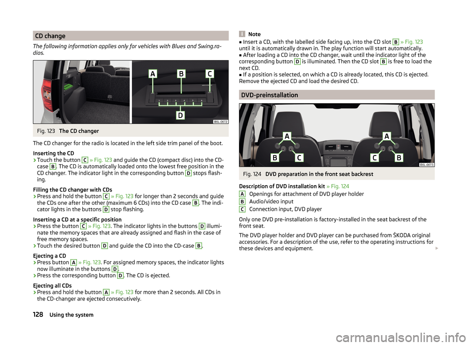
dios.Fig. 123
The CD changer
The CD changer for the radio is located in the left side trim panel of the boot.
Inserting the CD
›
Touch the button
C
» Fig. 123 and guide the CD (compact disc) into the CD-
case
B
. The CD is automatically loaded onto the lowest free position in the
CD changer. The indicator light in the corresponding button
D
stops flash-
ing.
Filling the CD changer with CDs
›
Press and hold the button
C
» Fig. 123 for longer than 2 seconds and guide
the CDs one after the other (maximum 6 CDs) into the CD case
B
. The indi-
cator lights in the buttons
D
stop flashing.
Inserting a CD at a specific position
›
Press the button
C
» Fig. 123 . The indicator lights in the buttons
D
illumi-
nate the memory spaces that are already assigned and flash in the case of
free memory spaces.
›
Touch the desired button
D
and guide the CD into the CD-case
B
.
Ejecting a CD
›
Press button
A
» Fig. 123 . For assigned memory spaces, the indicator lights
now illuminate in the buttons
D
.
›
Press the corresponding button
D
. The CD is ejected.
Ejecting all CDs
›
Press and hold the button
A
» Fig. 123 for more than 2 seconds. All CDs in
the CD-changer are ejected consecutively.
Note■ Insert a CD, with the labelled side facing up, into the CD slot B » Fig. 123
until it is automatically drawn in. The play function will start automatically.■
After loading a CD into the CD changer, wait until the indicator light of the
corresponding button
D
is illuminated. Then the CD slot
B
is free to load the
next CD.
■
If a position is selected, on which a CD is already located, this CD is ejected.
Remove the ejected CD and load the desired CD.
DVD-preinstallation
Fig. 124
DVD preparation in the front seat backrest
Description of DVD installation kit » Fig. 124
Openings for attachment of DVD player holder
Audio/video input
Connection input, DVD player
Only one DVD pre-installation is factory-installed in the seat backrest of the
front seat.
The DVD player holder and DVD player can be purchased from ŠKODA original
accessories. For a description of the use, refer to the operating instructions for
these devices and equipment.
ABC128Using the system
Page 133 of 248
Automatic connection
The connection to SmartGate is automatically restored under the following
conditions.
Wi-Fi is turned on in the device to be connected.
The ignition is switched on.
The device to be connected stores the password required for the connec-
tion check.
Connection problems
If the connection fails, check the following points.
› Are the conditions for a successful connection fulfilled?
› Is SmartGate available in the list of available Wi-Fi networks?
› Has the password required for the connection check been entered?
› Is the password is required for the connection check correct?
› Is the device to be connected still connected to another Wi-Fi network?
If the above items are ok but the connection still fails, contact a ŠKODA part-
ner.
Note
Up to four devices can be connected to SmartGate at a time.
Smart Gate website
Read and observe
on page 129 first.
There is a special website for the SmartGate system.
The following address must be entered in the web browser of the connected
device.
HTTP://192.168.123.1
This website contains information about the vehicle, the Wi-Fi connection and
SmartGate.
In the Configuration area the Wi-Fi connection settings can be adjusted.
Save the setting changes
The setting changes are only applied after performing the following steps.
› The changes are saved by pressing the “Save” button.
› SmartGate is restarted by pressing the “Reboot ”button.
Password Management
Read and observe
on page 129 first.
Passwords can be managed in the connected device on the SmartGate web-site » page 130 , Smart Gate website .
The changes are applied after saving and restarting SmartGate » page 130,
Save the setting changes .
Change password
›
Enter a new password in the Configuration area in menu option WPA / WPA2 key.
The password must be 8-17 characters without diaktritica or special characters
(for example, -, / , etc.).
Connection option without entering a password
›
In the Configuration area set the value Open in the menu item Security .
Forgot password
If you have forgotten your password, SmartGate must be reset to factory set-
tings in a specialized workshop.
130Using the system
Page 139 of 248
The brake pads wear more quickly if a lot of journeys are completed in towns
and over short distances or if a very sporty style of driving is adopted.
If operated under severe conditions , the thickness of the brake pads must be
checked by a specialist garage between service appointments as well.
Wet roads or road salt
The performance of the brakes can be delayed as the brake discs and brake
pads may be moist or have a coating of ice or layer of salt on them in winter.
The brakes are cleaned and dried by applying the brakes several times »
.
Corrosion
Corrosion on the brake discs and dirt on the bake pads occur if the vehicle has
been parked for a long period and if you do not make much use of the braking
system. The brakes are cleaned and dried by applying the brakes several
times »
.
Long or steep slopes
Before travelling a long distance with a steep gradient, reduce speed and shift
into the next lowest gear. As a result, the braking effect of the engine will be
used, reducing the load on the brakes. Any additional braking should be com-
pleted intermittently, not continuously.
Emergency brake display
If the brakes are applied in full and the control unit for the braking system con-
siders the situation to be dangerous for the following traffic, the brake light
flashes automatically.
After the speed was reduced below around 10 km/h or the vehicle was stop-
ped, the brake light stops flashing and the hazard warning light system
switches on. The hazard warning light system is switched off automatically af- ter accelerating or driving off again.
Faults in the brake surface
If it is found that the braking distance has suddenly become longer and that
the brake pedal can be depressed further, the brake system may be faulty.
Visit a specialist garage immediately and adjust your style of driving appropri-
ately, as you will not know the exact extent of the damage.
Low brake fluid level
An insufficient level of brake fluid may result in problems in the brake system.
The level of the brake fluid is monitored electronically » page 35,
Brake sys-
tem .
Brake booster
The brake booster increases the pressure generated with the brake pedal. The
brake booster only operates when the engine is running.WARNINGOnly apply the brakes for the purpose of drying and cleaning the brake
discs if the traffic conditions permit this. Do not place any other road users
in jeopardy.
Handbrake
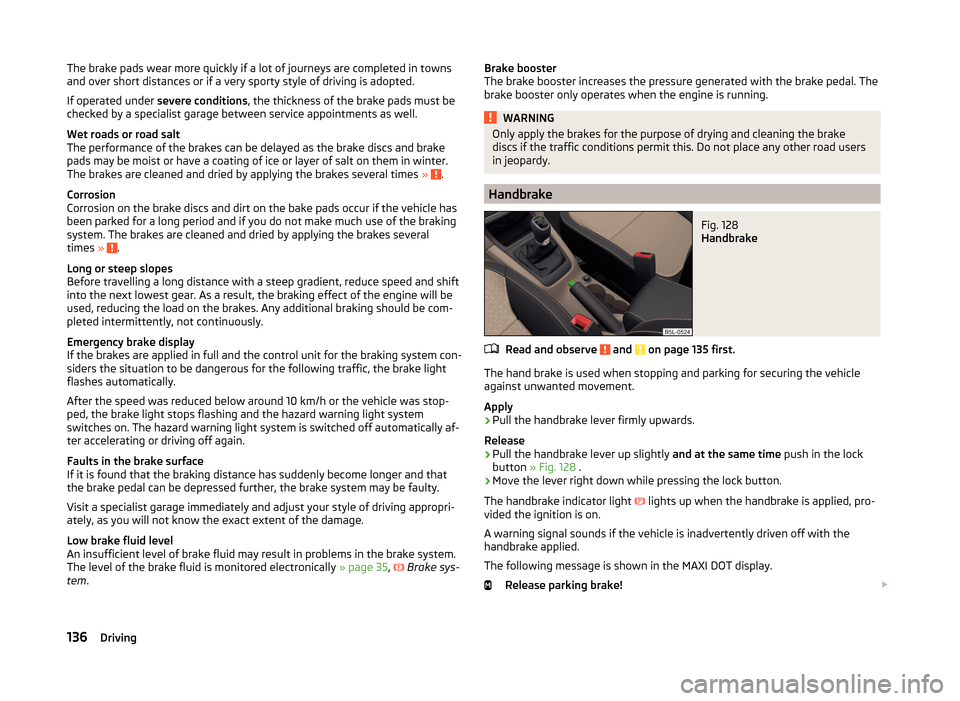
Fig. 128
Handbrake
Read and observe and on page 135 first.
The hand brake is used when stopping and parking for securing the vehicle
against unwanted movement.
Apply
›
Pull the handbrake lever firmly upwards.
Release
›
Pull the handbrake lever up slightly and at the same time push in the lock
button » Fig. 128 .
›
Move the lever right down while pressing the lock button.
The handbrake indicator light
lights up when the handbrake is applied, pro-
vided the ignition is on.
A warning signal sounds if the vehicle is inadvertently driven off with the
handbrake applied.
The following message is shown in the MAXI DOT display. Release parking brake!
136Driving
Page 162 of 248
Hitch and trailer
Hitch
Introduction
This chapter contains information on the following subjects:
Description
159
Adjusting the ready position
160
Correctly set ready position
160
Installing the ball rod
161
Check proper fitting
161
Removing the ball rod
162
Accessories
163
The maximum trailer drawbar load is 80 kg/h.
On vehicles with four-wheel drive and the 2.0 l / 103 kW TDI CR or 2.0 L / 125
kW TDI CR engine, the maximum trailer nose weight is 85 kg .
WARNING■
Check that the tow bar is seated correctly and is secured in the mounting
recess before the start of every journey.■
Do not use the ball head, if it is not correctly inserted into the mounting
recess and secured.
■
Do not use the towing equipment if it is damaged or incomplete.
■
Do not modify or adapt the towing device in any way.
■
Never release the tow bar while the trailer is still coupled.
■
Keep the mounting recess of the towing equipment clean at all times.
Such dirt prevents the ball head from being attached securely.
CAUTION
■ Take care with the ball bar - risk of paint damage to the bumper.■Always attach the cap to the receiving shaft when the ball bar is removed -
risk of receiving-shaft contamination.
Note
■ Operation and maintenance of towing equipment » page 174.■The towing vehicle by means of the detachable ball rod » page 209.DescriptionFig. 147
Carrier for the towing device/tow bar
Read and observe
and on page 159 first.
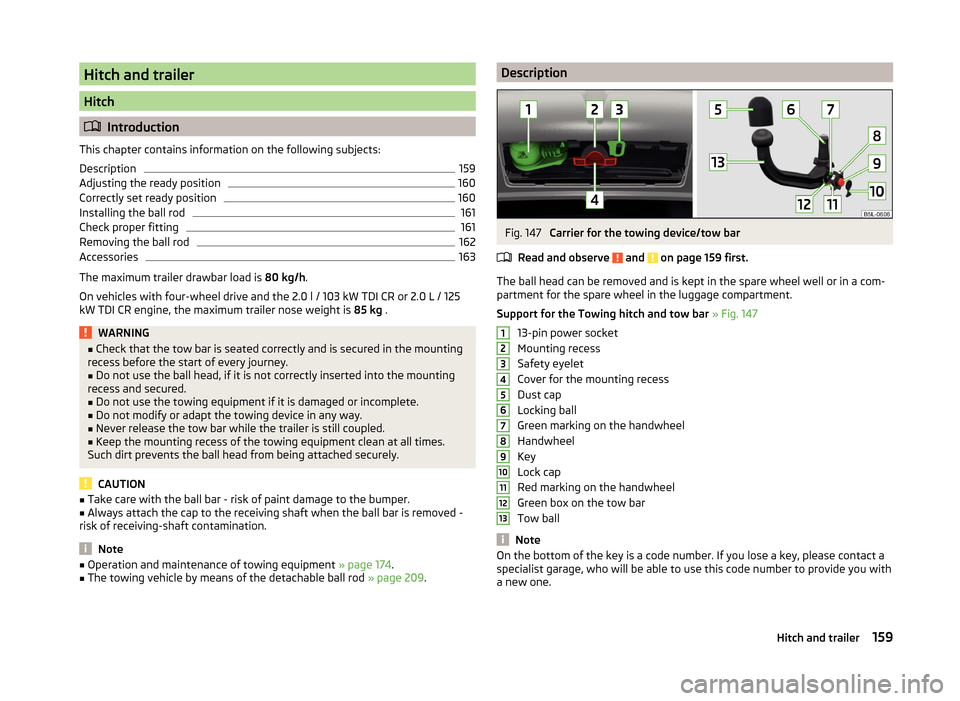
The ball head can be removed and is kept in the spare wheel well or in a com-
partment for the spare wheel in the luggage compartment.
Support for the Towing hitch and tow bar » Fig. 147
13-pin power socket
Mounting recess
Safety eyelet
Cover for the mounting recess
Dust cap
Locking ball
Green marking on the handwheel
Handwheel
Key
Lock cap
Red marking on the handwheel
Green box on the tow bar
Tow ball
Note
On the bottom of the key is a code number. If you lose a key, please contact a
specialist garage, who will be able to use this code number to provide you with
a new one.12345678910111213159Hitch and trailer
Page 164 of 248
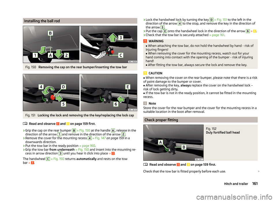
Installing the ball rodFig. 150
Removing the cap on the rear bumper/inserting the tow bar
Fig. 151
Locking the lock and removing the the key/replacing the lock cap
Read and observe
and on page 159 first.
›
Grip the cap on the rear bumper
B
» Fig. 150 at the handle
A
, release in the
direction of the arrow
1
and remove in the direction of the arrow
2
.
›
Remove the cover for the mounting recess
4
» Fig. 147 on page 159 in a
downwards direction.
›
Put the tow bar in the ready position » page 160.
›
Grip the tow bar from underneath » Fig. 150 and insert into the mounting re-
cess in arrow direction
3
until you hear it click into place » .
The handwheel
C
» Fig. 150 returns automatically and rests on the tow
bar » .
›Lock the handwheel lock by turning the key D
» Fig. 151 to the left in the
direction of the arrow 4 to the stop, and remove the key in the direction of
the arrow 5
.
›
Put the cap
E
onto the handwheel lock in the direction of the arrow
6
» .
›
Check that the tow bar is securely attached » page 161.
WARNING■
When attaching the tow bar, do not hold the handwheel by hand - risk of
injuring fingers!■
When removing the cover for the mounting recess, watch out for your
hand coming into contact with the opening of the bumper - risk of injuring
hand!
■
After fitting the tow bar, always secure the lock and remove the key.
CAUTION
■ When removing the cover on the rear bumper, please note that there is a risk
of paint damage to the bumper or cover.■
After removing the key, always replace the cover on the handwheel lock –
risk of lock getting dirty.
■
If the tow bar is not in the ready position, it cannot be fitted in the mounting
recess.
Note
Store the cover for the rear bumper and the cover for the mounting recess in a
suitable location in the boot after removal.
Check proper fitting
Fig. 152
Duly fortified ball head
Read and observe and on page 159 first.
Check that the tow bar is fitted properly before each use.
161Hitch and trailer
Page 165 of 248
Correctly secured ball head » Fig. 152
The tow bar does not come out of the mounting recess even after heavy
“shaking”.
The green marking A
on the handwheel is located in the green box on the
tow bar.
The handwheel lies flush with the tow bar - there is no gap.
The key is removed.
The cover
B
is attached to the locked handwheel lock.
WARNINGDo not use the towing equipment unless the ball head has been properly
locked - risk of accident.
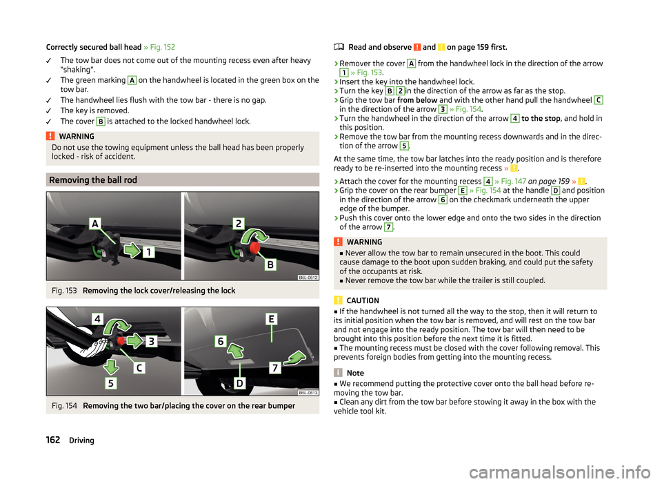
Removing the ball rod
Fig. 153
Removing the lock cover/releasing the lock
Fig. 154
Removing the two bar/placing the cover on the rear bumper
Read and observe and on page 159 first.›
Remover the cover
A
from the handwheel lock in the direction of the arrow
1
» Fig. 153 .
›
Insert the key into the handwheel lock.
›
Turn the key
B
2
in the direction of the arrow as far as the stop.
›
Grip the tow bar from below and with the other hand pull the handwheel
C
in the direction of the arrow
3
» Fig. 154 .
›
Turn the handwheel in the direction of the arrow
4
to the stop , and hold in
this position.
›
Remove the tow bar from the mounting recess downwards and in the direc-
tion of the arrow
5
.
At the same time, the tow bar latches into the ready position and is therefore
ready to be re-inserted into the mounting recess »
.
›
Attach the cover for the mounting recess
4
» Fig. 147 on page 159 » .
›
Grip the cover on the rear bumper
E
» Fig. 154 at the handle
D
and position
in the direction of the arrow
6
on the checkmark underneath the upper
edge of the bumper.
›
Push this cover onto the lower edge and onto the two sides in the direction
of the arrow
7
.
WARNING■ Never allow the tow bar to remain unsecured in the boot. This could
cause damage to the boot upon sudden braking, and could put the safety
of the occupants at risk.■
Never remove the tow bar while the trailer is still coupled.
CAUTION
■ If the handwheel is not turned all the way to the stop, then it will return to
its initial position when the tow bar is removed, and will rest on the tow bar
and not engage into the ready position. The tow bar will then need to be
brought into this position before the next time it is fitted.■
The mounting recess must be closed with the cover following removal. This
prevents foreign bodies from getting into the mounting recess.
Note
■ We recommend putting the protective cover onto the ball head before re-
moving the tow bar.■
Clean any dirt from the tow bar before stowing it away in the box with the
vehicle tool kit.
162Driving
Page 167 of 248

If the trailer that is to be towed has a 7-pin connector, you can use a suitable
adapter from ŠKODA Original Accessories to establish a connection to the elec-
tricity.›
Hook the breakaway cable of the trailer onto the safety eyelet
B
.
The breakaway cable of the trailer has to sag when mounted into the security
lock slot for all trailer positions relative to the vehicle (sharp curves, reverse
driving and the like.)
Uncoupling
›
Unhook the breakaway cable of the trailer from the safety eyelet
B
» Fig. 156 .
›
Unplug the trailer cable from the 13-pin socket.
›
Remove the trailer from the ball head.
›
Place the cap
5
» Fig. 147 on page 159 onto the ball head.
›
Grip the 13-pin socket at point
A
and swing in the opposite direction to the
arrow » Fig. 156 .
Exterior mirrors
You have to have additional exterior mirrors fitted if you are not able to see
the traffic behind the trailer with the standard rear-view mirrors. The national
legal requirements must be observed.
Headlights
The front of the vehicle may lift up when a trailer is being towed and the head-
lights may dazzle other road users.
Adjust the headlights using the headlight beam control » page 64,
Lights
and visibility 1)
.
WARNING■ Incorrect or improperly connected electrical installation can cause acci-
dents and serious injury due to electric shock.■
Work on the electrical system must only be carried out by specialist ga-
rages.
■
Never directly connect the trailer's electrical system with the electrical
connections for the tail lights or other current sources.
■
After coupling the trailer and connecting up the power socket, check the
rear lights on the trailer to ensure they are working.
WARNING (Continued)■ The handbrake on the towing vehicle must be applied when coupling and
uncoupling the trailer.■
Never use the safety eyelet for towing!
CAUTION
Incorrect or improperly connected electrical installations may cause malfunc-
tion of the entire vehicle electronics.
Loading a trailer
The vehicle/trailer combination must be balanced, whereby the maximum per-
missible drawbar load must be utilised. If the drawbar load is too low, it jeop-
ardises the performance of the vehicle/trailer combination.
Distribution of the load
Distribute the load in the trailer in such a way that heavy items are located as
close to the axle as possible. Secure the items from slipping.
The distribution of the weight is very poor if your vehicle is unladen and the
trailer is laden. Maintain a particularly low speed if you cannot avoid driving
with this combination.
Tyre pressure
Correct the tyre inflation pressure on your vehicle for a “full load” » page 191.
Towing capacity and trailer weight
The permissible trailer load must not be exceeded under any circumstan-
ces » page 222 , Technical data .
The details given in the vehicle's technical documentation always take prece-
dence over the details in the Owner's Manual.
The trailer loads specified apply only to altitudes up to 1 000 metres above
mean sea level.
The engine output falls as altitude increases, as does the vehicle's climbing
power. Therefore, for every additional 1000 m in height (or part), the maximum
permissible towed weight must be reduced by 10%.
The towed weight is made up of the actual weights of the loaded towing vehi-
cle and the loaded trailer.
1)
Applies to vehicles with bi-xenon headlights.
164Driving