ECU SKODA YETI 2014 1.G / 5L Owner's Guide
[x] Cancel search | Manufacturer: SKODA, Model Year: 2014, Model line: YETI, Model: SKODA YETI 2014 1.G / 5LPages: 248, PDF Size: 29.49 MB
Page 180 of 248
Inspecting and replenishing
Fuel
Introduction
This chapter contains information on the following subjects:
Refuelling
177
Lead-free petrol
178
Diesel fuel
179
The correct fuel grades for your vehicle are specified on the inside of the fuel
filler flap » Fig. 157 on page 177 .
CAUTION
■
Never drive until the fuel tank is completely empty! The irregular supply of
fuel can cause misfiring, which can result in damage to parts of the engine and
the exhaust system.■
Immediately remove any fuel that has spilled onto the vehicle's paintwork –
risk of paint damage!
■
If the vehicle was not purchased in the country where it was intended to be
operated, you should check whether the fuel specified by the manufacturer is
offered in the country where the vehicle will be operated. You should also per-
haps check whether the manufacturer has recommended a different fuel for
operation of the vehicle in the corresponding country. If no prescribed fuel is
available, then you must check whether it is permitted by the manufacturer to
operate the vehicle with another fuel type.
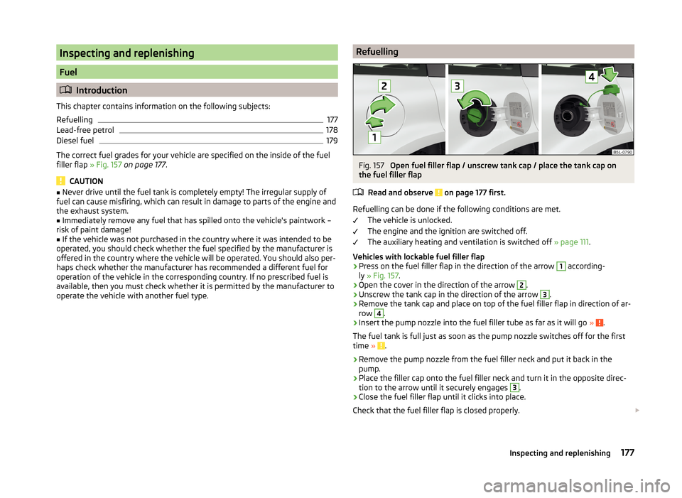
RefuellingFig. 157
Open fuel filler flap / unscrew tank cap / place the tank cap on
the fuel filler flap
Read and observe
on page 177 first.
Refuelling can be done if the following conditions are met. The vehicle is unlocked.
The engine and the ignition are switched off.
The auxiliary heating and ventilation is switched off » page 111.
Vehicles with lockable fuel filler flap
›
Press on the fuel filler flap in the direction of the arrow
1
according-
ly » Fig. 157 .
›
Open the cover in the direction of the arrow
2
.
›
Unscrew the tank cap in the direction of the arrow
3
.
›
Remove the tank cap and place on top of the fuel filler flap in direction of ar-
row
4
.
›
Insert the pump nozzle into the fuel filler tube as far as it will go » .
The fuel tank is full just as soon as the pump nozzle switches off for the first
time »
.
›
Remove the pump nozzle from the fuel filler neck and put it back in the
pump.
›
Place the filler cap onto the fuel filler neck and turn it in the opposite direc-
tion to the arrow until it securely engages
3
.
›
Close the fuel filler flap until it clicks into place.
Check that the fuel filler flap is closed properly.
177Inspecting and replenishing
Page 182 of 248
Fuel additives
Unleaded petrol in accordance with the EN 228 standard 1)
meets all the condi-
tions for a smooth-running engine. We therefore recommend that no fuel ad-
ditives are used. This can result in considerable damage to parts of the engine
or the exhaust system.
CAUTION
■ Even filling the tank with petrol that does not meet the standards once can
lead to serious damage to parts of the exhaust system!■
If a fuel other than unleaded fuel which complies to the above mentioned
standards (e.g. leaded petrol) is put in the tank by mistake, do not start the en-
gine or switch on the ignition! Extensive damage to engine parts can occur!
CAUTION
■ If, in an emergency, the vehicle has to be refuelled with petrol of a lower oc-
tane number than the one prescribed, the journey must only be continued at
medium engine speeds and a low engine load. Driving at high engine revs or a
high engine load can severely damage the engine! Refuel using petrol of the
prescribed octane number as soon as possible.■
Engine parts can be damaged if petrol with a lower octane number than the
one prescribed is used.
■
Even in the event of an emergency, petrol of a lower octane number than 91
RON must not be used, otherwise the engine can be severely damaged!
CAUTION
In no case may fuel additives with metal components be used, especially not
with manganese and iron content. Risk of causing considerable damage to
parts of the engine or exhaust system!
CAUTION
Fuels with metal components, such as LRP (lead replacement petrol) must
not be used. Risk of causing considerable damage to parts of the engine or
exhaust system!Note■ Unleaded petrol that has a higher octane number than that required by the
engine can be used without limitations.■
On vehicles with prescribed unleaded petrol 95/91, 92 or 93 RON, the use of
petrol with a higher octane number than 95 RON does not result in a noticea-
ble power increase or a lower fuel consumption.
■
On vehicles using prescribed unleaded petrol of min. 95 RON, the use of pet-
rol with a higher octane number than 95 RON can increase the power and re-
duce fuel consumption.
Diesel fuel
Read and observe
on page 177 first.
The vehicle can only be operated with diesel fuel that meets the EN 5902)
standard.
All diesel engines can be operated using diesel fuel with at most 7% biodiesel
(B7) 3)
.
On the Indian market, your vehicle will only be able to run on diesel fuel com-
pliant with standard IS 1460/Bharat IV. If diesel fuel which complies with this
standard is not available, you can refuel with diesel fuel according to standard
IS 1460/Bharat III in case of emergency.
Operation in winter - Winter-grade diesel fuel
In the cold season, only use “winter-grade diesel fuel” which will still operate
properly even at a temperature of -20 °C.
It is often the case in countries with different climatic conditions that diesel
fuels available have a different temperature characteristic. ŠKODA Partners
and filling stations in the relevant country will be able to provide you with in-
formation regarding the diesel fuels available.
Preheating fuel
The vehicle is fitted with a fuel filter preheating system. This secures opera-
tion of a vehicle using diesel fuel down to an environmental temperature of
-25 °C.
1)
In Germany also DIN 51626-1 or E10 for unleaded petrol with octane number 91 or 95 or DIN 51626-2 or E5
for unleaded petrol with octane number 95 and 98.
2)
In Germany also DIN 51628, in Austria ÖNORM C 1590, in Russia GOST R 52368-2005 / EN 590:2004.
3)
In Germany according to the DIN 52638 standard, in Austria ÖNORM C 1590, in France EN 590.
179Inspecting and replenishing
Page 184 of 248
WARNING■Read and observe the information and warning instructions on the fluid
containers.■
Keep the working fluids in sealed original containers and safe from peo-
ple who are not completely independent, e.g. children.
■
Never spill operating fluids over the hot engine - risk of fire.
■
If you intend to work underneath the vehicle, you must secure the vehicle
from rolling away and support it with suitable supporting blocks; the car
jack is not sufficient – risk of injury!
CAUTION
Always top up using the correct specification of fluids. This may result in major
operating problems and also vehicle damage!
For the sake of the environment
In view of the requirements for the environmentally friendly disposal of fluids and the special tools and knowledge required for such work, we recommend
that fluids be changed by a specialist garage.
Note
■ Please consult a specialist garage for any questions relating to fluids.■Fluids with the proper specifications can be purchased from the ŠKODA Origi-
nal Accessories or from the ŠKODA Genuine Parts ranges.
Opening and closing the bonnet
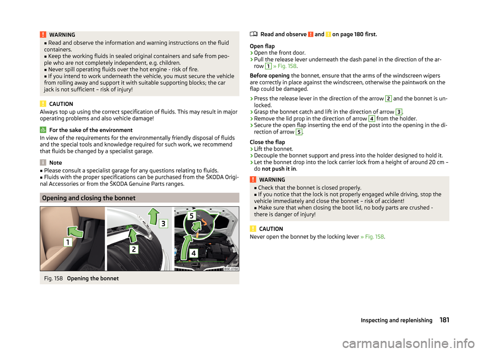
Fig. 158
Opening the bonnet
Read and observe and on page 180 first.
Open flap
›
Open the front door.
›
Pull the release lever underneath the dash panel in the direction of the ar-
row
1
» Fig. 158 .
Before opening the bonnet, ensure that the arms of the windscreen wipers
are correctly in place against the windscreen, otherwise the paintwork on the
flap could be damaged.
›
Press the release lever in the direction of the arrow
2
and the bonnet is un-
locked.
›
Grasp the bonnet catch and lift in the direction of arrow
3
.
›
Remove the lid prop in the direction of arrow
4
from the holder.
›
Secure the open flap inserting the end of the post into the opening in the di-
rection of arrow
5
.
Close the flap
›
Lift the bonnet.
›
Decouple the bonnet support and press into the holder designed to hold it.
›
Let the bonnet drop into the lock carrier lock from a height of around 20 cm –
do not push it in .
WARNING■
Check that the bonnet is closed properly.■If you notice that the lock is not properly engaged while driving, stop the
vehicle immediately and close the bonnet – risk of accident!■
Make sure that when closing the boot lid, no body parts are crushed -
there is danger of injury!
CAUTION
Never open the bonnet by the locking lever » Fig. 158.181Inspecting and replenishing
Page 192 of 248
Air bubbles can influence the colour of the indicator. For this reason carefully
knock on the indicator before carrying out the check.
› Black colour - electrolyte level is correct.
› Colourless or light yellow colour - electrolyte level too low, the battery must
be replaced.
Vehicles with a START-STOP system are fitted with a battery control unit for
checking the energy level for recurring engine start.
We recommend that you have the acid level checked regularly by a specialist garage, especially in the following cases.
› High external temperatures.
› Longer day trips.
› After each charge.
Winter time
The vehicle battery only has a proportion of the starting power in lower tem-
peratures. A discharged vehicle battery may already freeze at temperatures
just below 0 °C .
We therefore recommend that you have the battery checked and, if necessary,
recharged by a specialist garage before the start of the winter.
Note
■ The battery acid level is also checked regularly by a specialist garage as part
of the inspection service.■
For technical reasons, on vehicles with the description “AGM”, the electrolyte
level cannot be checked.
Charging
Read and observe
and on page 187 first.
A properly charged vehicle battery is essential for reliably starting the engine.A charging operation can be performed if the following conditions are satis-
fied.
The engine is turned off.
The ignition is switched off.
All consumers are turned off.
The bonnet is open.
“Fast charging” with high currents
›
Disconnect both battery cables (first of all “negative”, then “positive”).
› Attach the terminal clamps of the charger to the battery terminals (red =
“positive”, black = “negative”).›
Plug the mains cable of the charger into the power socket and switch on the
device.
›
After charging has been successful: Switch off the charger and remove the
mains cable from the power socket.
›
Only then disconnect the charger's terminal clamps.
›
Reconnect the cables to the battery (first “positive”, then “negative”).
Charging with low voltages
It is not necessary to disconnect the cables from the battery if you recharge
the vehicle battery, for example from a mini-charger.
Refer to the instructions of the charger manufacturer .
A charging current of 0.1 multiple of the total vehicle battery capacity (or low-
er) must be used until full charging is achieved.
The vent plugs of the vehicle battery should not be opened for charging.
WARNING■ When you charge a battery, hydrogen is released, and a highly explosive
gas mixture is also produced. An explosion can be caused through sparkling
over during unclamping or loosening of the cable plug while the ignition is
on.■
Creating a bridge between the poles on the battery (e.g. with metal ob-
jects - cables) creates a short circuit - risk of damage to the battery, explo-
sion and burning of the battery, jets of acid spurting out.
■
Avoid creating sparks when working with cables and electrical devices.
Strong sparking represents a risk of injury.
■
Before carrying out any work on the electrical system, switch off the en-
gine, the ignition and all electrical consumers and disconnect the negative
terminal
.
■
“Quick-charging” the vehicle battery is dangerous and requires a special
charger and specialist knowledge.
■
We therefore recommend that vehicle batteries be “rapidly charged” by a
specialist garage.
CAUTION
On vehicles with the START / STOP system or additional heating (auxiliary
heating), do not connect the pole terminal of the charger directly to the nega-
tive terminal of the vehicle battery but only to the engine earth » page 206.189Inspecting and replenishing
Page 200 of 248
Do-it-yourself
Emergency equipment and self-help
Emergency equipment
Introduction
This chapter contains information on the following subjects:
Placement of the first aid kit and warning triangle
197
Placement of the reflective vest
197
Fire extinguisher
197
Vehicle tool kit
198
Placement of the first aid kit and warning triangle
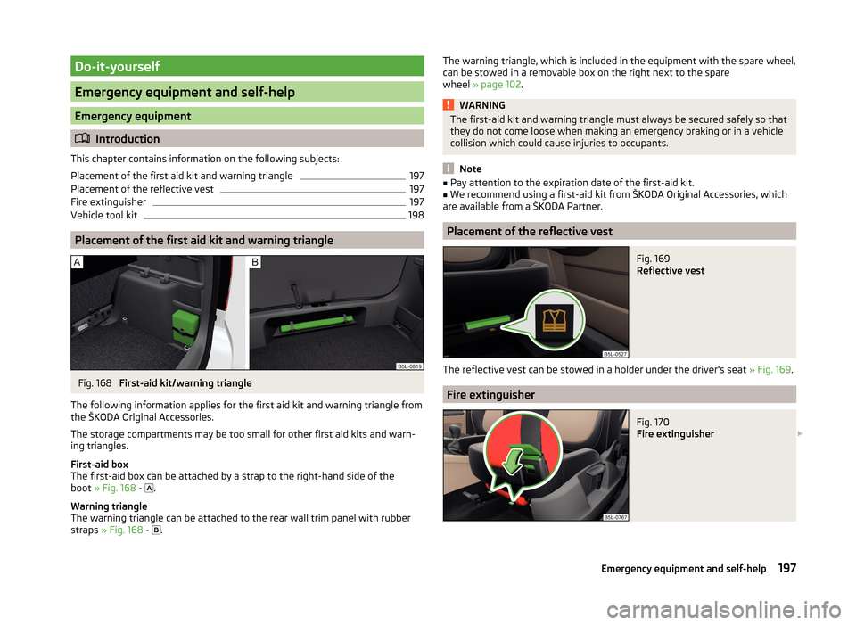
Fig. 168
First-aid kit/warning triangle
The following information applies for the first aid kit and warning triangle from the ŠKODA Original Accessories.
The storage compartments may be too small for other first aid kits and warn-
ing triangles.
First-aid box
The first-aid box can be attached by a strap to the right-hand side of the
boot » Fig. 168 -
.
Warning triangle
The warning triangle can be attached to the rear wall trim panel with rubber
straps » Fig. 168 -
.
The warning triangle, which is included in the equipment with the spare wheel,
can be stowed in a removable box on the right next to the spare
wheel » page 102 .WARNINGThe first-aid kit and warning triangle must always be secured safely so that
they do not come loose when making an emergency braking or in a vehicle
collision which could cause injuries to occupants.
Note
■ Pay attention to the expiration date of the first-aid kit.■We recommend using a first-aid kit from ŠKODA Original Accessories, which
are available from a ŠKODA Partner.
Placement of the reflective vest
Fig. 169
Reflective vest
The reflective vest can be stowed in a holder under the driver's seat » Fig. 169.
Fire extinguisher
Fig. 170
Fire extinguisher
197Emergency equipment and self-help
Page 201 of 248
The fire extinguisher is attached by two straps in a holder underneath the driv-
er's seat.
Removing/attaching›
Loosen the two straps by pulling the buckles in the direction of the ar-
row » Fig. 170 .
›
Remove the fire extinguisher.
›
Secure the fire extinguisher by placing it back into the holder and fastening
with straps.
Please read carefully the instructions which are attached to the fire extin-
guisher.
The fire extinguisher must be checked by an authorised person once a year.
The national legal requirements must be observed.
WARNINGThe fire extinguisher must always be secured safely so that they do not
come loose when making an emergency braking or in a vehicle collision
which could cause injuries to occupants.
Note
■ The fire extinguisher must comply with national legal requirements.■Pay attention to the expiration date of the fire extinguisher. If the fire extin-
guisher is used after the expiration date, its proper function is not assured.■
The fire extinguisher is part of the scope of delivery in certain countries only.
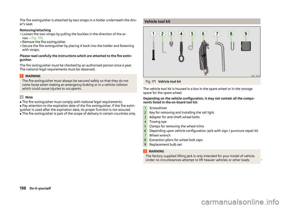
Vehicle tool kitFig. 171
Vehicle tool kit
The vehicle tool kit is housed in a box in the spare wheel or in the storage
space for the spare wheel.
Depending on the vehicle configuration, it may not contain all the compo-
nents listed in the on-board tool kit.
Screwdriver
Key for removing and installing the tail light
Adapter for anti-theft wheel bolts
Towing eye
Clamps for removing the wheel trims
Depending upon vehicle configuration: Jack with sign / puncture repair kit
Wheel wrench
Extraction pliers for wheel bolt caps
Replacement bulb set
WARNINGThe factory-supplied lifting jack is only intended for your model of vehicle.
Under no circumstances attempt to lift heavier vehicles or other loads. 123456789198Do-it-yourself
Page 202 of 248
CAUTION■Screw the jack back into the starting position before storing in the box with
the tool kit.■
Ensure that the vehicle tool kit is safely secured in the boot.
■
Ensure that the box is always secured with the strap.
Note
The declaration of conformity is included with the jack or the log folder.
Reserve and temporary spare
Introduction
This chapter contains information on the following subjects:
Remove / store wheel
199
Spare wheel
199
If you need to use an emergency or spare wheel, make sure to fit a standard
wheel of the appropriate dimensions and design as soon as possible.
After changing the spare wheel, the tyre pressure should be adjusted. In vehi- cles with tyre pressure monitoring, save tyre pressure values » page 158.
WARNING■
If you have to fit the spare tyre with a non-specified direction or an oppo-
site direction of rotation due to a puncture, then drive carefully. The best
properties of the tyre are no longer present in this situation.■
If the dimensions or design of the spare wheel differ from the tyres fitted
to the vehicle (e.g. winter tyres or low-profile tyres), it must only be used
briefly in the event of a puncture and if an appropriately cautious style of
driving is adopted.
■
If the dimensions or design of the temporary spare wheel differ from the
fitted tyres, never drive faster than 80 km/h (or 50 mph).
■
Never use the temporary spare wheel if it is damaged.
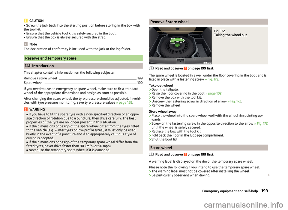
Remove / store wheelFig. 172
Taking the wheel out
Read and observe on page 199 first.
The spare wheel is located in a well under the floor covering in the boot and is
fixed in place with a fastening screw » Fig. 172.
Take out wheel
›
Open the tailgate.
›
Raise the floor covering in the boot » page 102.
›
Remove the box with the tool kit.
›
Unscrew the fastening screw in direction of arrow » Fig. 172.
›
Remove the wheel.
Store wheel away
›
Place the wheel into the spare wheel well with the wheel rim pointing up-
wards.
›
Screw on the fastening screw in the opposite direction to the arrow » Fig. 172
until the wheel is safely secured.
›
Replace the box with the tool kit.
›
Fold back the floor in the luggage compartment.
›
Shut the boot lid.
Spare wheel
Read and observe
on page 199 first.
A warning label is displayed on the rim of the temporary spare wheel.
Please note the following if you intend to use the temporary spare wheel. › The warning label must not be covered after installing the wheel.
› Be particularly observant when driving.
199Emergency equipment and self-help
Page 204 of 248
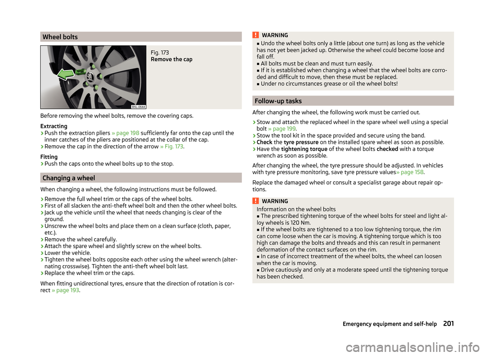
Wheel boltsFig. 173
Remove the cap
Before removing the wheel bolts, remove the covering caps.
Extracting
›
Push the extraction pliers » page 198 sufficiently far onto the cap until the
inner catches of the pliers are positioned at the collar of the cap.
›
Remove the cap in the direction of the arrow » Fig. 173.
Fitting
›
Push the caps onto the wheel bolts up to the stop.
Changing a wheel
When changing a wheel, the following instructions must be followed.
›
Remove the full wheel trim or the caps of the wheel bolts.
›
First of all slacken the anti-theft wheel bolt and then the other wheel bolts.
›
Jack up the vehicle until the wheel that needs changing is clear of the
ground.
›
Unscrew the wheel bolts and place them on a clean surface (cloth, paper, etc.).
›
Remove the wheel carefully.
›
Attach the spare wheel and slightly screw on the wheel bolts.
›
Lower the vehicle.
›
Tighten the wheel bolts opposite each other using the wheel wrench (alter-
nating crosswise). Tighten the anti-theft wheel bolt last.
›
Replace the wheel trim or the caps.
When fitting unidirectional tyres, ensure that the direction of rotation is cor-
rect » page 193 .
WARNING■
Undo the wheel bolts only a little (about one turn) as long as the vehicle
has not yet been jacked up. Otherwise the wheel could become loose and
fall off.■
All bolts must be clean and must turn easily.
■
If it is established when changing a wheel that the wheel bolts are corro-
ded and difficult to move, then these must be replaced.
■
Under no circumstances grease or oil the wheel bolts!
Follow-up tasks
After changing the wheel, the following work must be carried out.
›
Stow and attach the replaced wheel in the spare wheel well using a special
bolt » page 199 .
›
Stow the tool kit in the space provided and secure using the band.
›
Check the tyre pressure on the installed spare wheel as soon as possible.
›
Have the tightening torque of the wheel bolts checked with a torque
wrench as soon as possible.
After changing the wheel, the tyre pressure should be adjusted. In vehicles
with tyre pressure monitoring, save tyre pressure values » page 158.
Replace the damaged wheel or consult a specialist garage about repair op-
tions.
WARNINGInformation on the wheel bolts■The prescribed tightening torque of the wheel bolts for steel and light al-
loy wheels is 120 Nm.■
If the wheel bolts are tightened to a too low tightening torque, the rim
can come loose when the car is moving. A tightening torque which is too
high can damage the bolts and threads and this can result in permanent
deformation of the contact surfaces on the rim.
■
In case of incorrect treatment of the wheel bolts, the wheel can loosen
when the car is moving.
■
Drive cautiously and only at a moderate speed until the tightening torque
has been checked.
201Emergency equipment and self-help
Page 206 of 248
WARNINGNotes for vehicle lifting■Choose a flat and firm surface for jacking the vehicle.■
If the wheel has to be changed on a slope, first of all block the opposite
wheel with a stone or similar object to prevent the vehicle from unexpect-
edly rolling away.
■
Secure the base plate of the lifting jack with suitable means to prevent
possible moving. A soft and slippery ground under the base plate may move
the lifting jack, causing the vehicle to fall down. It is therefore always nec-
essary to place the lifting jack on a solid surface or use a wide and stable
base. Use a non-slip base (e.g. a rubber foot mat) if the surface is smooth,
such as cobbled stones, tiled floor, etc.
■
Only attach the lifting jack to the attachment points provided for this pur-
pose.
■
Always raise the vehicle with the doors closed.
■
Never position any body parts, such as arms or legs under the vehicle,
while the vehicle is raised with a lifting jack.
■
When the vehicle is raised, never start the engine.
CAUTION
It is important to ensure that the jack is correctly attached to the web of the
lower fork leg - risk of damage to the vehicle.
Anti-theft wheel bolts
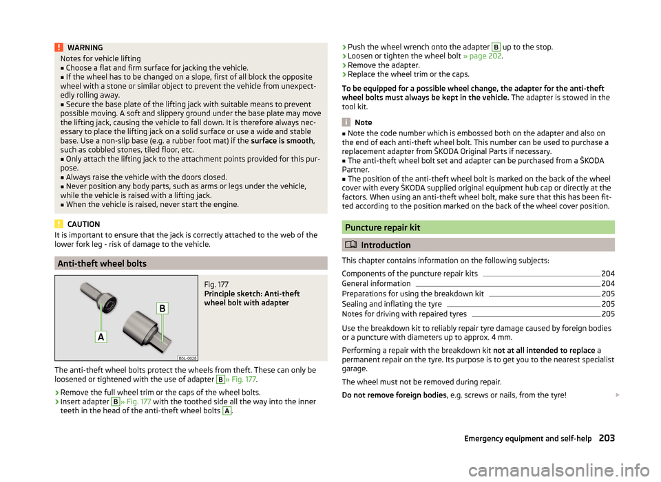
Fig. 177
Principle sketch: Anti-theft
wheel bolt with adapter
The anti-theft wheel bolts protect the wheels from theft. These can only be
loosened or tightened with the use of adapter
B
» Fig. 177 .
›
Remove the full wheel trim or the caps of the wheel bolts.
›
Insert adapter
B
» Fig. 177 with the toothed side all the way into the inner
teeth in the head of the anti-theft wheel bolts
A
.
› Push the wheel wrench onto the adapter B up to the stop.›Loosen or tighten the wheel bolt
» page 202.›
Remove the adapter.
›
Replace the wheel trim or the caps.
To be equipped for a possible wheel change, the adapter for the anti-theft
wheel bolts must always be kept in the vehicle. The adapter is stowed in the
tool kit.
Note
■ Note the code number which is embossed both on the adapter and also on
the end of each anti-theft wheel bolt. This number can be used to purchase a
replacement adapter from ŠKODA Original Parts if necessary.■
The anti-theft wheel bolt set and adapter can be purchased from a ŠKODA
Partner.
■
The position of the anti-theft wheel bolt is marked on the back of the wheel
cover with every ŠKODA supplied original equipment hub cap or directly at the
factors. When using an anti-theft wheel bolt, make sure that this has been fit-
ted according to the position marked on the back of the wheel cover position.
Puncture repair kit
Introduction
This chapter contains information on the following subjects:
Components of the puncture repair kits
204
General information
204
Preparations for using the breakdown kit
205
Sealing and inflating the tyre
205
Notes for driving with repaired tyres
205
Use the breakdown kit to reliably repair tyre damage caused by foreign bodies
or a puncture with diameters up to approx. 4 mm.
Performing a repair with the breakdown kit not at all intended to replace a
permanent repair on the tyre. Its purpose is to get you to the nearest specialist
garage.
The wheel must not be removed during repair.
Do not remove foreign bodies , e.g. screws or nails, from the tyre!
203Emergency equipment and self-help
Page 216 of 248
Service position for changing wiper blades›Closing the bonnet.›
Switch the ignition off and on again.
›
Press the control lever in position
4
within 10 seconds » page 73.
The windscreen wiper arms move into the service position.
Removing the wiper blade
›
Lift the wiper arm from the windscreen in the direction of
1
» Fig. 191 .
›
Press the securing clip
A
in the direction of arrow
2
to unlock the wiper
blade.
›
Remove the wiper blade in the direction of the arrow
3
.
Attaching the windscreen wiper blade
›
Push the windscreen wiper blade to the stop until it locks into place.
›
Check that the windscreen wiper blade is correctly attached.
›
Fold the wiper arms back to the windscreen.
The windscreen wiper arms move back into the rest position - after switching
on the ignition and changing the position of the window wiper lever or when
driving at a speed of more than 6°km/h.
CAUTION
If the windscreen wipers are handled carelessly, there is a risk of damage to
the windscreen.
Replacing the rear window wiper blade
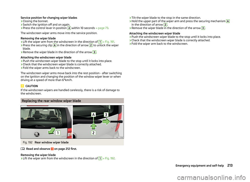
Fig. 192
Rear window wiper blade
Read and observe
on page 212 first.
Removing the wiper blade
›
Lift the wiper arm from the windscreen in the direction of
1
» Fig. 192 .
›Tilt the wiper blade to the stop in the same direction.›Hold the upper part of the wiper arm and press the securing mechanism A
in the direction of arrow
2
.
›
Remove the wiper blade in the direction of the arrow
3
.
Attaching the windscreen wiper blade
›
Push the windscreen wiper blade to the stop until it locks into place.
›
Check that the windscreen wiper blade is correctly attached.
›
Fold the wiper arm back to the windscreen.
213Emergency equipment and self-help