key SKODA YETI 2014 1.G / 5L Workshop Manual
[x] Cancel search | Manufacturer: SKODA, Model Year: 2014, Model line: YETI, Model: SKODA YETI 2014 1.G / 5LPages: 248, PDF Size: 29.49 MB
Page 161 of 248
If none of these conditions are met or if the driving style is not changed, the
system recommends a driving break again after 15 minutes.
Activation/deactivation
The system can be activated/deactivated via the MAXI DOT display in the As-
sistants menu option » page 47.
Information messages
Read and observe
on page 157 first.
In MAXI DOT display the icon appears for a few seconds and the following
message.
Fatigue detected. Take a break!
An audible signal is also emitted.
Tyre pressure monitoring
Introduction
This chapter contains information on the following subjects:
Save tyre pressure values
158
The tyre pressure monitoring function (hereinafter referred to only as a sys-
tem) monitors the tyre pressure while driving.
If the rolling circumference of a wheel is changed, the warning light in the
instrument cluster lights up and an audible signal sounds.
Information on the procedure for the notification of change of tyre inflation
pressure » page 40 .
The system can only function properly if the tyres have the prescribed inflation
pressure and these pressure values are stored in the system.
WARNING■ Having the correct tyre inflation pressure is always the driver's responsi-
bility. Tyre pressure should be checked regularly » page 191.■
The system cannot warn in case of very rapid tyre inflation pressure loss,
e.g. in case of sudden tyre damage.
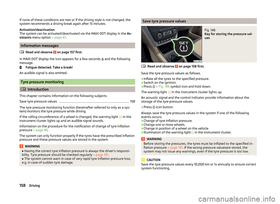
Save tyre pressure valuesFig. 146
Key for storing the pressure val-
ues
Read and observe on page 158 first.
Save the tyre pressure values as follows.
›
Inflate all the tyres to the specified pressure.
›
Switch on the ignition.
›
Press
» Fig. 146 symbol icon and hold down.
The warning light in the instrument cluster lights up.
An acoustic signal and the control indicator provide information about the
storage of the tyre pressure values.
›
Press icon button.
Always save the tyre pressure values in the system if one of the following
events occurs.
› Change of tyre inflation pressure.
› Change one or more wheels.
› Change in position of a wheel on the vehicle.
› Illumination of the warning light
in the instrument cluster.
WARNINGBefore storing the pressures, the tyres must be inflated to the specified in-
flation pressure » page 191. If the wrong pressure valuesare stored, the
system may not issue any warnings, even if the tyre pressure is too low.
CAUTION
Save the tyre pressure values every 10,000 km or 1x annually to ensure correct
system functioning.158Driving
Page 162 of 248
Hitch and trailer
Hitch
Introduction
This chapter contains information on the following subjects:
Description
159
Adjusting the ready position
160
Correctly set ready position
160
Installing the ball rod
161
Check proper fitting
161
Removing the ball rod
162
Accessories
163
The maximum trailer drawbar load is 80 kg/h.
On vehicles with four-wheel drive and the 2.0 l / 103 kW TDI CR or 2.0 L / 125
kW TDI CR engine, the maximum trailer nose weight is 85 kg .
WARNING■
Check that the tow bar is seated correctly and is secured in the mounting
recess before the start of every journey.■
Do not use the ball head, if it is not correctly inserted into the mounting
recess and secured.
■
Do not use the towing equipment if it is damaged or incomplete.
■
Do not modify or adapt the towing device in any way.
■
Never release the tow bar while the trailer is still coupled.
■
Keep the mounting recess of the towing equipment clean at all times.
Such dirt prevents the ball head from being attached securely.
CAUTION
■ Take care with the ball bar - risk of paint damage to the bumper.■Always attach the cap to the receiving shaft when the ball bar is removed -
risk of receiving-shaft contamination.
Note
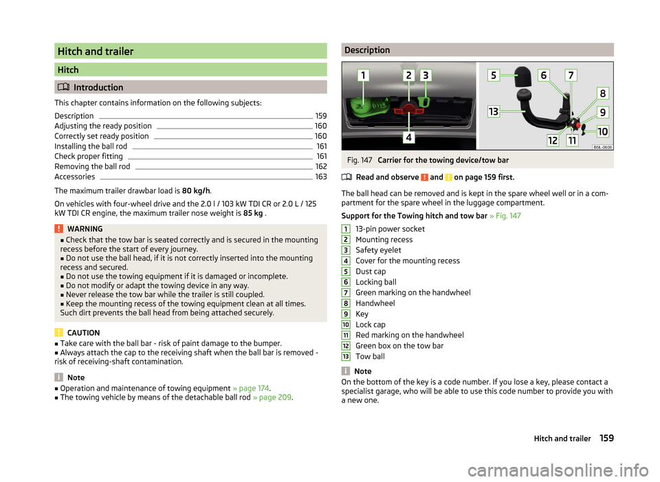
■ Operation and maintenance of towing equipment » page 174.■The towing vehicle by means of the detachable ball rod » page 209.DescriptionFig. 147
Carrier for the towing device/tow bar
Read and observe
and on page 159 first.
The ball head can be removed and is kept in the spare wheel well or in a com-
partment for the spare wheel in the luggage compartment.
Support for the Towing hitch and tow bar » Fig. 147
13-pin power socket
Mounting recess
Safety eyelet
Cover for the mounting recess
Dust cap
Locking ball
Green marking on the handwheel
Handwheel
Key
Lock cap
Red marking on the handwheel
Green box on the tow bar
Tow ball
Note
On the bottom of the key is a code number. If you lose a key, please contact a
specialist garage, who will be able to use this code number to provide you with
a new one.12345678910111213159Hitch and trailer
Page 163 of 248
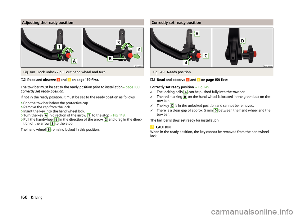
Adjusting the ready positionFig. 148
Lock unlock / pull out hand wheel and turn
Read and observe
and on page 159 first.
The tow bar must be set to the ready position prior to installation » page 160,
Correctly set ready position .
If not in the ready position, it must be set to the ready position as follows.
›
Grip the tow bar below the protective cap.
›
Remove the cap from the lock
›
Insert the key into the hand wheel lock.
›
Turn the key
A
in direction of the arrow
1
to the stop » Fig. 148.
›
Pull the handwheel
B
in the direction of the arrow
2
and drag in the direc-
tion of the arrow
3
to the stop.
The hand wheel
B
remains locked in this position.
Correctly set ready positionFig. 149
Ready position
Read and observe
and on page 159 first.
Correctly set ready position » Fig. 149
The locking balls
A
can be pushed fully into the tow bar.
The red marking
B
on the hand wheel is located in the green box on the
tow bar.
The key
C
is in the unlocked position and cannot be removed.
There is a clear gap of approx. 5 mm
D
between the hand wheel and the
tow bar.
The ball bar is thus set ready for installation.
CAUTION
When in the ready position, the key cannot be removed from the handwheel
lock.160Driving
Page 164 of 248
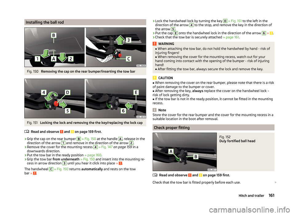
Installing the ball rodFig. 150
Removing the cap on the rear bumper/inserting the tow bar
Fig. 151
Locking the lock and removing the the key/replacing the lock cap
Read and observe
and on page 159 first.
›
Grip the cap on the rear bumper
B
» Fig. 150 at the handle
A
, release in the
direction of the arrow
1
and remove in the direction of the arrow
2
.
›
Remove the cover for the mounting recess
4
» Fig. 147 on page 159 in a
downwards direction.
›
Put the tow bar in the ready position » page 160.
›
Grip the tow bar from underneath » Fig. 150 and insert into the mounting re-
cess in arrow direction
3
until you hear it click into place » .
The handwheel
C
» Fig. 150 returns automatically and rests on the tow
bar » .
›Lock the handwheel lock by turning the key D
» Fig. 151 to the left in the
direction of the arrow 4 to the stop, and remove the key in the direction of
the arrow 5
.
›
Put the cap
E
onto the handwheel lock in the direction of the arrow
6
» .
›
Check that the tow bar is securely attached » page 161.
WARNING■
When attaching the tow bar, do not hold the handwheel by hand - risk of
injuring fingers!■
When removing the cover for the mounting recess, watch out for your
hand coming into contact with the opening of the bumper - risk of injuring
hand!
■
After fitting the tow bar, always secure the lock and remove the key.
CAUTION
■ When removing the cover on the rear bumper, please note that there is a risk
of paint damage to the bumper or cover.■
After removing the key, always replace the cover on the handwheel lock –
risk of lock getting dirty.
■
If the tow bar is not in the ready position, it cannot be fitted in the mounting
recess.
Note
Store the cover for the rear bumper and the cover for the mounting recess in a
suitable location in the boot after removal.
Check proper fitting
Fig. 152
Duly fortified ball head
Read and observe and on page 159 first.
Check that the tow bar is fitted properly before each use.
161Hitch and trailer
Page 165 of 248
Correctly secured ball head » Fig. 152
The tow bar does not come out of the mounting recess even after heavy
“shaking”.
The green marking A
on the handwheel is located in the green box on the
tow bar.
The handwheel lies flush with the tow bar - there is no gap.
The key is removed.
The cover
B
is attached to the locked handwheel lock.
WARNINGDo not use the towing equipment unless the ball head has been properly
locked - risk of accident.
Removing the ball rod
Fig. 153
Removing the lock cover/releasing the lock
Fig. 154
Removing the two bar/placing the cover on the rear bumper
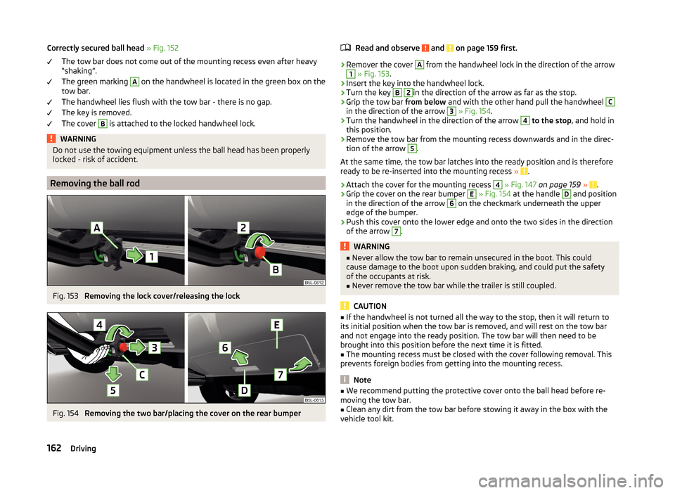
Read and observe and on page 159 first.›
Remover the cover
A
from the handwheel lock in the direction of the arrow
1
» Fig. 153 .
›
Insert the key into the handwheel lock.
›
Turn the key
B
2
in the direction of the arrow as far as the stop.
›
Grip the tow bar from below and with the other hand pull the handwheel
C
in the direction of the arrow
3
» Fig. 154 .
›
Turn the handwheel in the direction of the arrow
4
to the stop , and hold in
this position.
›
Remove the tow bar from the mounting recess downwards and in the direc-
tion of the arrow
5
.
At the same time, the tow bar latches into the ready position and is therefore
ready to be re-inserted into the mounting recess »
.
›
Attach the cover for the mounting recess
4
» Fig. 147 on page 159 » .
›
Grip the cover on the rear bumper
E
» Fig. 154 at the handle
D
and position
in the direction of the arrow
6
on the checkmark underneath the upper
edge of the bumper.
›
Push this cover onto the lower edge and onto the two sides in the direction
of the arrow
7
.
WARNING■ Never allow the tow bar to remain unsecured in the boot. This could
cause damage to the boot upon sudden braking, and could put the safety
of the occupants at risk.■
Never remove the tow bar while the trailer is still coupled.
CAUTION
■ If the handwheel is not turned all the way to the stop, then it will return to
its initial position when the tow bar is removed, and will rest on the tow bar
and not engage into the ready position. The tow bar will then need to be
brought into this position before the next time it is fitted.■
The mounting recess must be closed with the cover following removal. This
prevents foreign bodies from getting into the mounting recess.
Note
■ We recommend putting the protective cover onto the ball head before re-
moving the tow bar.■
Clean any dirt from the tow bar before stowing it away in the box with the
vehicle tool kit.
162Driving
Page 168 of 248
The trailer and drawbar load information on the type plate of the towing de-
vice is merely a test value for the towing device. The vehicle-specific values
are detailed in the vehicle documents.WARNING■ Never exceed the maximum permissible axle and drawbar load or the per-
missible weight of the trailer - risk of accident!■
Sliding cargo can significantly adversely affect stability and driving safety
- risk of accident!
Towing a trailer
Driving speed
For safety reasons, do not drive faster than 80 km/h when towing a trailer.
Immediately reduce your speed as soon as even the slightest swaying of the
trailer is detected. Never attempt to stop the trailer from “swaying” by acceler-
ating.
Brakes
Apply the brakes in good time! If the trailer is fitted with a trailer brake, apply
the brakes gently at first, then brake firmly. This will avoid brake jolts resulting
from the trailer wheels locking.
On downhill sections shift down a gear in good time to also use the engine as
a brake.
Engine overheating
If the needle for the coolant temperature gauge moves into the right-hand
area or the red area of the scale, the speed must be reduced immediately.
Stop and switch off the engine if the indicator light in the instrument cluster
starts to flash.
The following guidelines must be observed » page 36,
Coolant
.
The coolant temperature can be reduced by switching on the heating.
WARNING■ Always drive particularly carefully with the trailer.■Adapt your speed to the conditions of the road surface and to the traffic
situation.CAUTIONIf you tow a trailer frequently, you should also have your vehicle inspected be-
tween service intervals.
Anti-theft alarm system
If the vehicle is locked, the alarm is activated when the electrical connection to
the trailer is interrupted.
Always switch off the anti-theft alarm system before a trailer is coupled or un-
coupled » page 56 .
Conditions for including a trailer in the anti-theft alarm system. The vehicle is factory-fitted with an anti-theft alarm system and towing
device.
The trailer is electrically connected to the towing vehicle via the trailer
socket.
The electrical system of the vehicle and trailer is functional.
The vehicle is locked with the vehicle key and the anti-theft alarm system
is activated.
CAUTION
For technical reasons, trailers with rear LED lights cannot be connected to the
anti-theft alarm system.165Hitch and trailer
Page 181 of 248
Vehicles without lockable fuel filler flap›Press on the fuel filler flap in the direction of the arrow 1 according-
ly » Fig. 157 .›
Open the cover in the direction of the arrow
2
.
›
Hold the filler cap and unlock by turning the key in the direction of the arrow
3
.
›
Unscrew the tank cap in the direction of the arrow
3
.
›
Remove the tank cap and place on top of the fuel filler flap in direction of ar-
row
4
.
›
Insert the pump nozzle into the fuel filler tube as far as it will go » .
The fuel tank is full just as soon as the pump nozzle switches off for the first
time »
.
›
Remove the pump nozzle from the fuel filler neck and put it back in the
pump.
›
Screw in the tank cap in the opposite direction of the arrow
3
until it audibly
clicks into place.
›
Hold the filler cap and lock it by turning in the opposite direction of the arrow
3
. Remove the key.
›
Close the fuel filler flap until it clicks into place.
Check that the fuel filler flap is closed properly.
WARNING■ Do not smoke when refuelling and do not use a mobile phone.■Fuel vapours are explosive - can be fatal!■
Observe the local regulations regarding fuel handling.
WARNINGInstructions for filling the reserve canister■Never fill the reserve can inside the vehicle.■
Never place the reserve can on the vehicle.
■
Always place the reserve can on the floor.
■
The national legal requirements must be observed if carrying a spare can-
ister in the vehicle.
■
We do not recommend carrying any fuel canisters in your vehicle for safe-
ty reasons. in the event of an accident, these canisters can become dam-
aged and fuel may escape – risk of fire!
CAUTION■ The fuel tank is full just as soon as the pump nozzle switches off for the first
time, provided the nozzle has been operated properly. Not continue refuelling.■
Be careful when filling diesel fuel from the spare canister and then do this
slowly and cautiously – danger of contaminating the body.
Note
The fuel capacity for vehicles with front wheel drive is about 55 litres, and for
vehicles with four-wheel drive about 60 litres, with about 9 liters as reserve.
Lead-free petrol
Read and observe
on page 177 first.
The vehicle can only be operated with unleaded petrol in compliance with the
EN 228 1)
standard.
All petrol engines can be operated using petrol that contains at most 10% bio-
ethanol (E10).
Required fuel - unleaded petrol 95/91 or 92 or 93 RON
Use unleaded fuel with the octane rating 95 RON. Unleaded petrol with the
octane ratings 91, 92 or 93 RON can also be used, but may result in a slight
loss in performance and slightly increased fuel consumption »
.
Prescribed fuel - unleaded petrol min. 95 RON
Use unleaded fuel with the octane rating 95 RON or higher.
If unleaded gasoline is not available with the octane number 95 RON, in an
emergency petrol with the octane rating of 91, 92 and 93 RON can be used to
fill the tank, but this leads to a slight loss of performance and a slightly in-
creased fuel consumption »
.
Prescribed fuel - unleaded fuel 98/95 RON
Use unleaded fuel with the octane rating 98 RON or higher. Unleaded petrol
95 RON can also be used but this results in a slight loss in performance and
slightly increased fuel consumption.
In case of an emergency, you can refuel with petrol with the octane ratings 91,
92 or 93 RON, if unleaded fuel with octane rating 98 RON or 95 RON is not
available »
.
1)
In Germany also DIN 51626-1 or E10 for unleaded petrol with octane number 91 or 95 or DIN 51626-2 or E5
for unleaded petrol with octane number 95 and 98.
178General Maintenance
Page 183 of 248
Diesel fuel additives
The diesel fuel in accordance with the prescribed standards meets all the con-
ditions for a smooth running engine. We therefore recommend that no fuel ad-
ditives are used. This can result in considerable damage to parts of the engine
or the exhaust system.
CAUTION
■ Just filling the tank once with diesel fuel that does not comply with the
standard, can cause severe damage to parts of the engine, the fuel and ex-
haust system!■
If a different fuel other than diesel fuel, which complies to the above men-
tioned standards (e.g. petrol) is put into the tank, do not start the engine or
switch on the ignition! Extensive damage to engine parts can occur!
■
Water which has collected in the fuel filter can cause engine faults.
CAUTION
■ The vehicle cannot be operated with biofuel RME, therefore this fuel must
not be refuelled and driven. The use of biofuel RME can cause considerable
damage to parts of the engine or fuel system.■
Do not mix any fuel additives, so-called “flow improvers” (petrol and similar
agents) into the diesel. This can result in considerable damage to parts of the
engine or the exhaust system!
Engine compartment
Introduction
This chapter contains information on the following subjects:
Opening and closing the bonnet
181
Engine compartment overview
182
Radiator fan
182
Windscreen washer system
182WARNINGInjuries or scolding or risks of accident or fire may occur when working in
the engine compartment. For this reason, it is essential to comply with the
warning instructions outlined below and with the general applicable safety
rules. The engine compartment of your car is a hazardous area!WARNINGInstructions before beginning work in the engine compartment■Turn off the engine and withdraw the ignition key.■
Firmly apply the handbrake.
■
For vehicles with manual transmission the lever into the neutral position.
■
On vehicles with automatic transmission, shift the selector lever into the
P position.
■
Allow the engine to cool.
■
Never open the bonnet if you can see steam or coolant escaping from the
engine compartment – risk of scalding! Wait until no more steam or coolant
is escaping.
WARNINGInformation for working in the engine room■Keep all people, especially children, away from the engine compartment.■
Never touch the radiator fan while the engine is still warm. The fan might
suddenly start running!
■
Do not touch any hot engine parts – risk of burns!
WARNINGInformation for working in the engine compartment with the engine run-
ning■
Pay particular attention to moving engine parts, e.g. V-ribbed belt, gener-
ator, radiator fan - danger to life!
■
Never touch the electric wiring on the ignition system.
■
Avoid short circuits in the electrical system - particularly on the vehicle's
battery.
■
Always make sure that no jewellery, loose clothing or long hair can get
caught in rotating engine parts – risk to life! Always remove any jewellery,
tie back long hair and wear tight fitting clothing before completing any
work.
WARNINGInformation for working on the fuel system or the electrical system■Always disconnect the vehicle battery from the electrical system.■
Do not smoke.
■
Never work near open flames.
■
Always have a functioning fire extinguisher nearby.
180General Maintenance
Page 201 of 248
The fire extinguisher is attached by two straps in a holder underneath the driv-
er's seat.
Removing/attaching›
Loosen the two straps by pulling the buckles in the direction of the ar-
row » Fig. 170 .
›
Remove the fire extinguisher.
›
Secure the fire extinguisher by placing it back into the holder and fastening
with straps.
Please read carefully the instructions which are attached to the fire extin-
guisher.
The fire extinguisher must be checked by an authorised person once a year.
The national legal requirements must be observed.
WARNINGThe fire extinguisher must always be secured safely so that they do not
come loose when making an emergency braking or in a vehicle collision
which could cause injuries to occupants.
Note
■ The fire extinguisher must comply with national legal requirements.■Pay attention to the expiration date of the fire extinguisher. If the fire extin-
guisher is used after the expiration date, its proper function is not assured.■
The fire extinguisher is part of the scope of delivery in certain countries only.
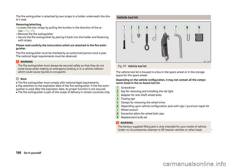
Vehicle tool kitFig. 171
Vehicle tool kit
The vehicle tool kit is housed in a box in the spare wheel or in the storage
space for the spare wheel.
Depending on the vehicle configuration, it may not contain all the compo-
nents listed in the on-board tool kit.
Screwdriver
Key for removing and installing the tail light
Adapter for anti-theft wheel bolts
Towing eye
Clamps for removing the wheel trims
Depending upon vehicle configuration: Jack with sign / puncture repair kit
Wheel wrench
Extraction pliers for wheel bolt caps
Replacement bulb set
WARNINGThe factory-supplied lifting jack is only intended for your model of vehicle.
Under no circumstances attempt to lift heavier vehicles or other loads. 123456789198Do-it-yourself
Page 212 of 248
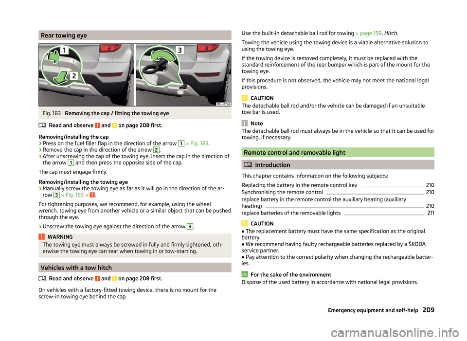
Rear towing eyeFig. 183
Removing the cap / fitting the towing eye
Read and observe
and on page 208 first.
Removing/installing the cap
›
Press on the fuel filler flap in the direction of the arrow
1
» Fig. 183 .
›
Remove the cap in the direction of the arrow
2
.
›
After unscrewing the cap of the towing eye, insert the cap in the direction of
the arrow
1
and then press the opposite side of the cap.
The cap must engage firmly.
Removing/installing the towing eye
›
Manually screw the towing eye as far as it will go in the direction of the ar-
row
3
» Fig. 183 » .
For tightening purposes, we recommend, for example, using the wheel
wrench, towing eye from another vehicle or a similar object that can be pushed
through the eye.
›
Unscrew the towing eye against the direction of the arrow
3
.
WARNINGThe towing eye must always be screwed in fully and firmly tightened, oth-
erwise the towing eye can tear when towing in or tow-starting.
Vehicles with a tow hitch
Read and observe
and on page 208 first.
On vehicles with a factory-fitted towing device, there is no mount for the
screw-in towing eye behind the cap.
Use the built-in detachable ball rod for towing » page 159, Hitch .
Towing the vehicle using the towing device is a viable alternative solution to using the towing eye.
If the towing device is removed completely, it must be replaced with the
standard reinforcement of the rear bumper which is part of the mount for the
towing eye.
If this procedure is not observed, the vehicle may not meet the national legal
provisions.
CAUTION
The detachable ball rod and/or the vehicle can be damaged if an unsuitable
tow bar is used.
Note
The detachable ball rod must always be in the vehicle so that it can be used for
towing, if necessary.
Remote control and removable light
Introduction
This chapter contains information on the following subjects:
Replacing the battery in the remote control key
210
Synchronising the remote control
210
replace battery in the remote control the auxiliary heating (auxiliary
heating)
210
replace batteries of the removable lights
211
CAUTION
■ The replacement battery must have the same specification as the original
battery.■
We recommend having faulty rechargeable batteries replaced by a ŠKODA
service partner.
■
Pay attention to the correct polarity when changing the rechargeable batter-
ies.
For the sake of the environment
Dispose of the used battery in accordance with national legal provisions.209Emergency equipment and self-help