heater SKODA YETI 2015 1.G / 5L User Guide
[x] Cancel search | Manufacturer: SKODA, Model Year: 2015, Model line: YETI, Model: SKODA YETI 2015 1.G / 5LPages: 232, PDF Size: 30.84 MB
Page 166 of 232
Note■The AdBlue ®
solution freezes at a temperature of -11 °C and below. The sys-
tem has a heater to ensure the operability at low temperatures.■
We recommend purchasing AdBlue ®
refill bottles from the ŠKODA original
parts.
■
AdBlue ®
is a registered trademark of the VDA. AdBlue ®
is also known as AUS
32 (Aqueous Urea Solution) or DEF (Diesel Exhaust Fluid).
Tank and level check
Read and observe
and on page 163 first.
Tank
AdBlue ®
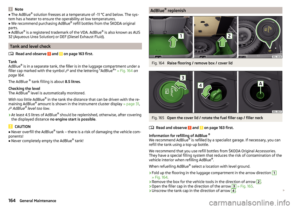
is in a separate tank, the filler is in the luggage compartment under a
filler cap marked with the symbol and the lettering “AdBlue ®
” » Fig. 164 on
page 164 .
The AdBlue ®
tank filling is about 8.5 litres.
Checking the level
The AdBlue ®
level is automatically monitored.
With too little AdBlue ®
in the tank the distance that can be driven with the re-
maining AdBlue ®
amount is shown in the instrument cluster display » page 31,
AdBlue ®
level too low .
›
At least 4.5 litres of AdBlue ®
should be replenished, otherwise, after covering
the displayed distance no engine start is possible .
CAUTION
■
Never overfill the AdBlue ®
tank – there is a risk of damaging the vehicle com-
ponents!■
Never completely empty the AdBlue ®
tank!
AdBlue ®
replenishFig. 164
Raise flooring / remove box / cover lid
Fig. 165
Open the cover lid / rotate the fuel filler cap / filler neck
Read and observe
and on page 163 first.
Information for refilling of AdBlue ®
We recommend AdBlue ®
is refilled by a specialist garage. If necessary, you can
refill the tank using a top-up bottle.
We recommend that you use refill bottles from ŠKODA Original Accessories.
They have a special filling system that reduces the risk of contamination of the
vehicle interior when refilling AdBlue ®
.
When refuelling AdBlue ®
select a location with level ground.
›
Fold up the flooring in the luggage compartment in the arrow direction
1
» Fig. 164 .
›
Remove the box for the vehicle tools in the direction of arrow
2
.
›
Open the filler cap in the direction of the arrow
3
» Fig. 165 .
›
Unscrew the tank cap in the direction of arrow
4
.
164General Maintenance
Page 172 of 232
The coolant additive share in the coolant must be at least. 40%.
The coolant additive may be increased to a maximum of 60%.
The correct mixing ratio of water and coolant additive is to be checked if nec-
essary by a specialist garage or is to be restored if necessary.
The description of the coolant is shown in the coolant expansion reservoir
» Fig. 170 on page 170 .WARNINGThe engine compartment of your car is a hazardous area. The following
warning instructions must be followed at all times when working in the en-
gine compartment » page 165.■
The coolant is harmful to health.
■
Avoid contact with the coolant.
■
Coolant vapours are harmful to health.
■
Never open the end cover of the coolant expansion reservoir while the
engine is still warm. The cooling system is pressurized!
■
When opening the end cover of the coolant expansion reservoir, cover it
with a cloth to protect your face, hands and arms from hot steam or hot
coolant.
■
If any coolant splashes into your eyes, immediately rinse out your eyes
with clear water and contact a doctor as soon as possible.
■
Always keep the coolant in the original container, safe from people who
are not completely independent, especially children - there is a danger of
poisoning!
■
If coolant is swallowed, consult a doctor immediately.
■
Never spill operating fluids over the hot engine - risk of fire.
CAUTION
■ Do not continue if for some reason it is not possible to fill with coolant un-
der the current circumstances! Switch off the engine and seek assistance from
a specialist garage.■
If the expansion tank is empty, do not top up with coolant. The system could
fill with air - risk of engine damage,
stop driving! Switch off the engine and
seek assistance from a specialist garage.
■
The concentration of coolant additive in the coolant must never be under
40%.
■
Over 60% of coolant additive in the coolant reduces the antifreeze protec-
tion and cooling effect.
■
A coolant additive that does not comply with the correct specification can
significantly reduce the corrosion protection of the cooling system.
■ Any faults resulting from corrosion may cause a loss of coolant and can con-
sequently result in major engine damage.■
Do not fill the coolant above the mark
A
» Fig. 170 on page 170 .
■
If an error occurs, leading to the engine overheating, the help of a professio-
nal garage is to be sought - there is a risk of serious engine damage occurring.
■
Additional headlights and other attached components in front of the air inlet
impair the cooling efficiency of the coolant.
■
Never cover the radiator - there is a risk of the engine overheating.
Note
The coolant capacity is approximately 1 l greater on vehicles that are fitted
with an auxiliary heater (auxiliary heating and ventilation).
Checking the coolant level
Fig. 170
Coolant expansion reservoir
Read and observe and on page 170 first.
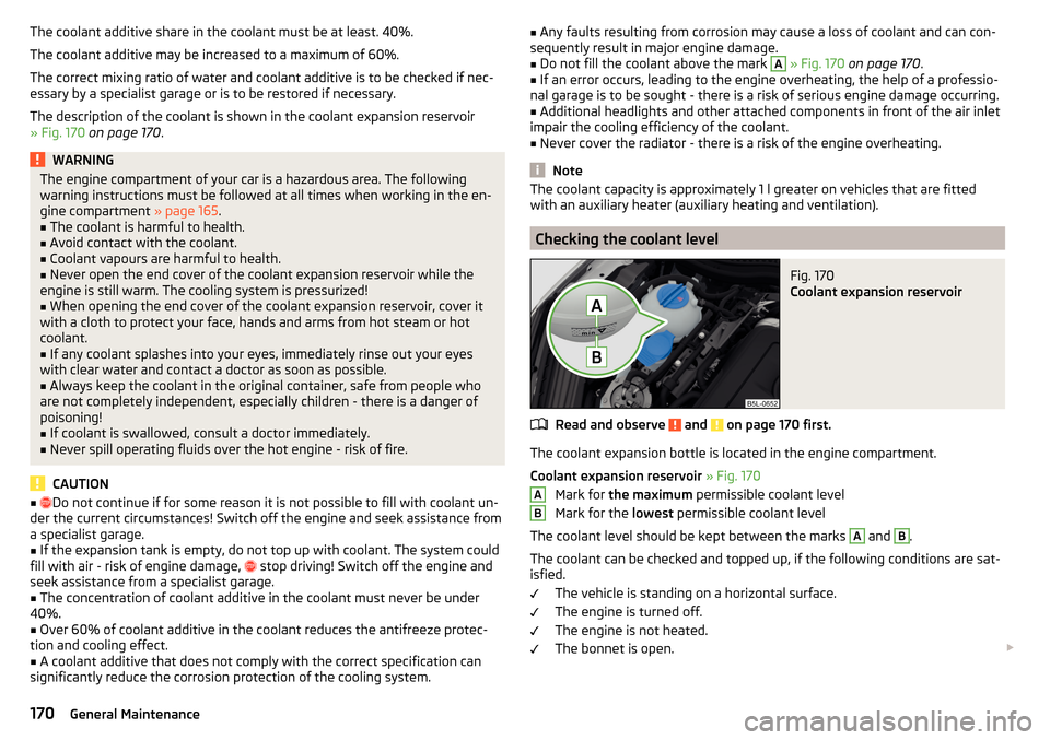
The coolant expansion bottle is located in the engine compartment.
Coolant expansion reservoir » Fig. 170
Mark for the maximum permissible coolant level
Mark for the lowest permissible coolant level
The coolant level should be kept between the marks
A
and
B
.
The coolant can be checked and topped up, if the following conditions are sat-
isfied.
The vehicle is standing on a horizontal surface.
The engine is turned off.
The engine is not heated.
The bonnet is open.
AB170General Maintenance
Page 177 of 232
CAUTIONOn vehicles with the START / STOP system or additional heating (auxiliary
heating), do not connect the pole terminal of the charger directly to the nega-
tive terminal of the vehicle battery but only to the engine earth » page 189.
Replacing
Read and observe
and on page 172 first.
The new vehicle battery must have the same capacity, voltage, current and the
same size as the original Battery. Suitable vehicle battery types can be pur-
chased from a specialist garage.
We recommend you have the battery replaced by a specialist garage.
Disconnecting and reconnecting
Read and observe
and on page 172 first.
Disconnecting
›
Switch off the ignition.
›
Disconnect the negative terminal first and then the positive
terminal of
the battery.
Connecting
›
Connect the positive terminal first, then the negative
battery terminal.
After disconnecting and re-connecting the vehicle battery, the following func-
tions or devices are partially or completely inoperative.
Function / deviceOperating measureElectrical power windows» page 61Panorama sliding/tilting roof» page 62Sun screen» page 63RadioEnter code » Owner's Manual
RadioTime settings» page 30CAUTION■ Disconnect the vehicle battery only with the ignition turned off - there is a
risk of damaging the electrical system of the vehicle.■
Under no circumstances must the battery cables be connected incorrectly –
risk of a cable fire.
Note
■ After disconnecting and re-connecting the vehicle battery, we recommend
having the vehicle checked by a specialist to ensure that the full functionality
of all electrical systems is guaranteed.■
The data of the multi-function display will be reset.
Automatic load deactivation
Read and observe
and on page 172 first.
The vehicle's electrical system automatically prevents the battery from dis-
charging when the battery is being heavily used. This manifests itself by the
following. ▶ The idling speed is raised to allow the generator to deliver more electricity to
the electrical system.
▶ Where necessary, large convenience consumers such as seat heaters and
rear window heaters have their power limited or are shut off completely in
the event of an emergency.
CAUTION
■ Despite such intervention by the vehicle electric system management, the
vehicle battery may be drained. For example, when the ignition is switched on
a long time with the engine turned off or the side or parking lights are turned
on during longer parking.■
Consumers that are supplied via a 12-V power socket can cause the vehicle
battery to discharge when the ignition is switched off.
Note
Driving comfort is not impaired by consumers being deactivated. The driver is
often not aware of it having taken place.175Inspecting and replenishing
Page 200 of 232
No.Consumer19ABS, ESP, switch for tyre air pressure control, parking aid, switch for
OFF ROAD mode, START STOP button20Switch, airbag21WIV, tail lamp, dimming mirror, pressure sensor, telephone prepara-
tion, air mass sensor, headlight range control and headlight tilt22Instrument cluster, electromechanical power steering, databus23Central locking system and bonnet lid24Rear power window25Rear window heater, auxiliary heating and ventilation26Power socket in the boot27Panorama window - sliding / tilting roof, electric sunblind28Fuel pump, injectors, AdBlue ®
heating29Front power window30front and rear lighter31Headlight cleaning system32Front seat heating, regulator for seat heating33Heating, air conditioning, Climatronic, remote control for auxiliary
heating34Alarm, spare horn35Automatic gearbox DSG36Tow hitch
Fuses in the engine compartment
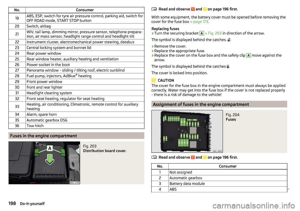
Fig. 203
Distribution board cover.
Read and observe and on page 196 first.
With some equipment, the battery cover must be opened before removing the
cover for the fuse box » page 173.
Replacing fuses
›
Turn the securing bracket
A
» Fig. 203 in direction of the arrow.
The symbol is displayed behind the catches.
.
›
Remove the cover.
›
Replace the appropriate fuse.
›
Replace the cover on the fuse box and the safety clip
A
move against the
arrow.
The symbol is displayed behind the catches .
The cover is locked into position.
CAUTION
The cover for the fuse box in the engine compartment must always be applied
correctly. Water may get into the fuse box if the cover is not replaced properly
- there is a risk of damage to the vehicle!
Assignment of fuses in the engine compartment
Fig. 204
Fuses
Read and observe and on page 196 first.
No.Consumer1Not assigned2Automatic gearbox3Battery data module4ABS 198Do-it-yourself
Page 201 of 232
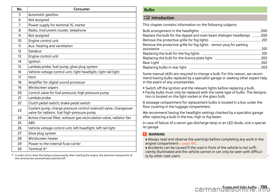
No.Consumer5Automatic gearbox6Not assigned7Power supply for terminal 15, starter8Radio, instrument cluster, telephone9Not assigned10Engine control unit11Aux. heating and ventilation12Databus13Engine control unit14Ignition15Lambda probe, fuel pump, glow plug system16Vehicle voltage control unit, right headlight, right tail light17Horn18Amplifier for digital sound processor19Windscreen wipers20Control valve for fuel pressure, high pressure pump21Lambda probe22Clutch pedal switch, brake pedal switch23Coolant pump, charge pressure control solenoid valve, changeover
valve for radiator, fuel high-pressure pump24Active charcoal filter, exhaust gas recirculation valve, radiator fan25ABS26Vehicle voltage control unit, left headlight, left tail light27Glow plug system28Windscreen heater29Power to the internal fuse carrier30Terminal X a)a)
In order not to drain the battery unnecessarily when starting the engine, the electrical components of
this terminal are automatically switched off.
Bulbs
Introduction
This chapter contains information on the following subjects:
Bulb arrangement in the headlights
200
Replace the bulb for the dipped and main beam (Halogen headlamp)
200
Remove the protective grille for fog lights
201
Remove the protective grille for fog lights - sensor plug for parking
assistance
201
Replacing the bulb for the fog lights
201
Replacing the bulb for the licence plate light
202
Rear Light
202
Replacing bulbs in rear light
203
Some manual skills are required to change a bulb. For this reason, we recom-
mend having bulbs replaced by a specialist garage or seeking other expert help
in the event of any uncertainties.
▶ Switch off the ignition and the relevant lights before replacing a bulb.
▶ Faulty bulbs must only be replaced with the same type of bulbs. The designa-
tion is located on the light socket or the glass bulb.
A stowage compartment for replacement bulbs is located in a box under the floor covering in the luggage compartment.
We recommend having the headlight settings checked by a specialist garage after replacing a bulb in the low, high or fog beam.
In case of failure of a xenon gas discharge lamp or an LED diode, visit a special- ist garage.
WARNING■ Always read and observe the warnings before completing any work in the
engine compartment » page 165.■
Accidents can be caused if the road in front of the vehicle is not suffi-
ciently illuminated and the vehicle cannot or can only be seen with difficul-
ty by other road users.
199Fuses and light bulbs
Page 219 of 232
G
Gear change Gear recommendation
40
Information on the selected gear40
Gear changing Gear stick
121
General view Cockpit
27
Genuine parts150
Glasses compartment90
Glow plug system Warning light
36
gradeability see pitch angle
208
H
Handbrake
120
Warning light33
Hazard warning light system68
HBA128
Head airbag19
Headlight cleaning system Headlight cleaning system
73
Headlights Bulb arrangement
200
Driving abroad69
Headlight cleaning system73
Headlights with CORNER function67
Head restraint79
Headrests adjusting
80
Heater Windscreen and rear window
70
Heating104
Air distribution control107
Controls105
Exterior mirrors74
Seats78
HHC128
Hill Start Assist (HHC)128
Hitch141
Drawback load141
Hook98
Horn27
I
Ignition lock
114
Immobilizer113
Individual settings Locking
55
Unlocking55
Inertia reel14
Information system39
Compass point display48
Display a low temperature39
Door warning40
Gear recommendation40
MAXI DOT display43
Multifunction display41
Operation41
Service interval display48
Infotainment4
Inserting the variable loading floor
102
Instrument cluster28
Auto Check Control31
Counter for distance driven30
Display29
Display of the second speedometer31
Fuel gauge30
Lighting70
Overview28
Revolutions counter29
see instrument cluster28
Temperature gauge29
Warning lights32
Instrument lighting70
Interior care157
Natural leather158
Interior light Front
69
Interior monitor57
iPad holder Behind the headrests
95
Handling95
ISOFIX23
J
Jack
182
- fit185
Maintenance156
Jump-starting189
K
KESSY Locking
53
Unlocking53
Key Lock
53
Start the engine114
Stopping the engine114
Switch off the ignition114
Switch on the ignition114
Unlock53
Knee airbag17
L
Lamp failure Warning light
36
Lamps Warning light
36
Leather Natural leather care
158
LEAVING HOME67
217Index
Page 222 of 232
rear seatsin the longitudinal direction81
Rear seats80
Fold back82
fold down seat back81
Fold down seat fully81
Removing seats82
Setting outer seat in the transverse direction82
Rear View Camera133
Function keys134
Operation134
Orientation Lines134
Rear view mirror Interior mirror
73
Rear window - heater70
Refuelling160
Fuel160
Remote control Locking
53
Replacing the battery193
Synchronisation process193
Unlocking53
Remote control key Replacing the battery
193
Removable light Removing light
101
replace batteries of the lights193
Removable through-loading bag93
Removing the variable loading floor
102
Repairs and technical alterations149
Replace Bulb for dipped beam (Halogen headlamp)
200
Bulb for main beam (Halogen headlamp)200
the battery in the auxiliary heating (auxiliary heating) in the remote control
193
replace - batteries of the lights193
Replacing bulb for fog lights
201
Bulb for the licence plate light202
Bulb in rear light203
Bulbs199
Fuses196
Fuses in the dash panel197
Fuses in the engine compartment198
Vehicle battery175
windscreen wiper blades195
Replacing windscreen wiper blades195
Replenishing Coolant
171
Engine oil169
Windscreen washer fluid167
Reversing camera Lens care
156
Revolutions counter29
Roof Load
104
Roof rack103
Roof load104
Rubber seals155
Running-in Brake linings
124
Engine124
Tyres124
S
SAFE See Safe securing system
54
SAFELOCK See Safe securing system
54
Safe securing system54
Safety8
Child safety21
Child safety seats21
Correct seated position8
Head restraints79
ISOFIX23
TOP TETHER25
Safety belts rear middle seat
13
Save electrical energy125
Save fuel125
Seals Vehicle care
155
Seat Front seat adjustment
75
Seat belt height adjustment
12
warning light33
Seat belts11
Belt tensioners14
fastening and unfastening13
Seatbelts Inertia reels
14
Seat belts The physical principle of a head-on collision
12
Seat electrical adjustment76
Seat functions78
Seats Electrical adjustment
76
Folding front passenger seat79
Front armrest78
Head restraints79
Heating78
Manual adjustment76
Memory Function of the electrically adjustable seat
76
Storing in memory of remote control key77
Seats and head restraint75
Securing the variable load floor in the raised position
103
Selector lever Refer to Selector lever
122
Selector lever lock (automatic gearbox) Warning light
39
Service150
Service interval display48
Setting Seat belt height
12
220Index
Page 225 of 232
Headlight glasses155
Interior care157
Maintenance154
Materials158
Natural leather158
Plastic parts155
Polishing vehicle paint work154
Rubber seals155
Safety belt159
Seat covers159
Under-body protections157
washing152
Vehicle condition See Auto-Check Control
31
Vehicle data sticker204
Vehicle data sticker and nameplate Vehicle data sticker and nameplate
204
Vehicle dimensions207
Vehicle height207
Vehicle Identification Number (VIN)204
Vehicle length207
Vehicle tool kit182
Vehicle width207
vest Location of the reflective vest
181
VIN Vehicle Identification Number
204
Visibility70
Visors see front sun visors
71
W
Warning lights
32
MAXI DOT display31
warning messages Diesel particulate filter
37
Warning symbols MAXI DOT display
31
see Warning lights32
Warning triangle181
warning when speeding42
Washing Automatic car wash system
153
by hand152
High-pressure cleaner153
Washing vehicles152
Waste container88
Water in the fuel filter Warning light
31
warning messages31
Weather conditions149
Wheel bolts Anti-theft wheel bolts
184
Caps184
Loosening and tightening185
Wheel rims176
Wheels Age of wheels
176
Changing182
Driving style177
Full trim183
General information176
Load index179
Remove183
Snow chains180
Speed symbol179
Storage of wheels176
stow183
Tyre damage178
Tyre pressure176
Tyre size179
Tyre wear177
Tyre wear indicator178
unidirectional tyres178
Wheel balance177
Wheel replacement178
Winter tyres180
Wi-Fi Connection50
Password50
Password change51
Setting51
Wi-Fi Direct Connection
50
Password change51
Setting51
Window operation Malfunctions
61
Windscreen Heater
70
Windscreen washer fluid Checking
167
Replenishing167
Warning light38
Winter167
Windscreen washer system167
Windscreen washers72
Windscreen wiper Replacing the rear window wiper blade
196
Windscreen wipers automatic rear window wipers
72
Cleaning windscreen wipers195
Replacing the front windscreen wipers195
Service position of windscreen wiper arms195
Windscreen washer fluid167
Windscreen wipers and washers71
Winter operation180
De-icing window155
Snow chains180
Winter tyres180
Winter tyres See Wheels
180
Wiper blades157
Wipers Maintaining wiper blades
157
Wiping interval72
223Index