display SKODA YETI 2015 1.G / 5L Repair Manual
[x] Cancel search | Manufacturer: SKODA, Model Year: 2015, Model line: YETI, Model: SKODA YETI 2015 1.G / 5LPages: 232, PDF Size: 30.84 MB
Page 137 of 232
Note■The orientation lines are immobile, and therefore the spacing of the bars be-
hind the vehicle will vary, depending on the vehicle load state and the road in-
clination.■
If reduced park assistance display is switched off the acoustic signal cannot
be turned off with the button
.
Park Assist
Introduction
This chapter contains information on the following subjects:
Functioning
135
Parking space search
136
Parking
137
Departing from a parallel parking space
137
Automatic brake assist
138
Information messages
138
Park Assist (hereinafter referred to as system) helps drivers park in suitable
parallel and perpendicular parking places or also to manoeuvre out of parallel
parking spaces.
The system takes over the steering movements when parking or leaving a
parking space. The driver operates the pedals and the shift lever or gear selec-
tor.
The state in which the steering wheel is operated by the system, is referred to
as parking operation.
The Park Assist is an extension of the parking aid » page 131 and operates on
the basis of data collected by the ultrasonic sensors.
For this reason, the chapter on the parking aid is to be read carefully and the safety notes are to be observed.
WARNING■ The general information relating to the use of assistance systems must
be observed » page 127, in section Introduction .■
During the parking process, the system automatically performs rapid
steering movements. While it is doing so, do not place your hands between
the steering wheel – risk of injury!
■
During a parking manoeuvre on loose or slippery surfaces (gravel, snow,
ice, etc.) you may stray from the calculated road. Therefore we suggest that
you do not use the system in such situations.
CAUTION
The correct evaluation of the parking space and the parking procedure de-
pends on the circumference of the wheels on the vehicle.■
The system only works correctly if the vehicle is fitted with the wheel size
approved by the manufacturer.
■
Abstain from using the system when the vehicle is fitted with snow chains or
a temporary spare wheel.
■
If wheels other than those approved by the manufacturer are mounted, the
resulting position of the vehicle in the parking space can differ slightly. This
can be avoided by readjusting the system at a specialist garage.
CAUTION
If other vehicles are parked behind the kerb or on it, the system can also guide
your vehicle beyond the kerb or onto it. Ensure that the wheels or the wheel
rims of your vehicle are not damaged and if necessary intervene in time.
Note
■ We recommend performing the parking at a safe speed to about 5 km / h.■The driver can stop the parking process at any time by pressing the symbol
key
» Fig. 149 on page 136 or by a driver steering intervention.
Functioning
Read and observe
and on page 135 first.
The system support is provided in the following manner.▶ While the parking space search is going on, a measurement and evaluation of
the parking space size is completed.
▶ Suitable parking spaces are shown in the display of the instrument cluster
(hereinafter only in the display).
135Assist systems
Page 138 of 232
▶The display shows instructions and information before the start and during
the parking.
▶ The road way is calculated that the vehicle uses during the parking.
▶ The front wheels are automatically rotated during the parking.
Conditions for the system function
The system can look for a parking space only if the following basic conditions
are met.
The system is activated.
The vehicle speed is less than 40 km / h (parallel parking).
The vehicle speed is less than 20 km / h (transverse parking).
The distance to a number of parked vehicles is approximately 0.5 - 1.5 m.
The TCS is activated » page 127, Braking and stabilisation systems .
The system can only carry out the parking if the following basic conditions are
met.
The vehicle is travelling less than about 7 km/h.
The parking procedure takes less than 6 minutes.
There is no driver intervention in the automatic steering operation.
Activation/deactivation
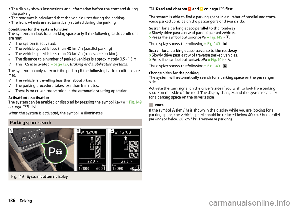
The system can be enabled or disabled by pressing the symbol key
» Fig. 149
on page 136 -
.
When the system is activated, the symbol illuminates.
Parking space search
Fig. 149
System button / display
Read and observe and on page 135 first.
The system is able to find a parking space in a number of parallel and trans-
verse parked vehicles on the passenger's or driver's side.
Search for a parking space parallel to the roadway
›
Slowly drive past a row of parallel parked vehicles.
›
Press the symbol button once
» Fig. 149 -
.
The display shows the following » Fig. 149 -
.
Search for a parking space traverse to the roadway
›
Slowly drive past a row of traverse parked vehicles.
›
Press the symbol button twice
» Fig. 149 -
.
The display shows the following » Fig. 149 -
.
Change sides for the parking
The system will automatically search for a parking space on the passenger
side.
Activate the turn signal on the driver's side if you wish to look fro a parking
space on this side of the road. The display changes and the system searches
for a parking space on the driver's side.
Note
If the symbol (km / h) is shown in the display while you are looking for a
parking space, the vehicle speed should be reduced below 40 km / hr (parallel parking) or below 20 km / hr (Transverse parking).136Driving
Page 139 of 232
ParkingFig. 150
Display
Read and observe
and on page 135 first.
The system supports the driver when reverse parking in the parking space
found in a number of traverse and parallel parked vehicles.
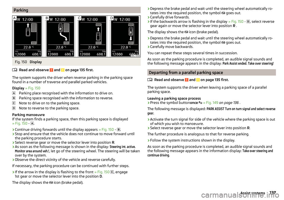
Display » Fig. 150
Parking place recognised with the information to drive on.
Parking space recognised with the information to reverse.
Note to drive on to the parking space.
Note to reverse to the parking space.
Parking manoeuvre
If the system finds a parking space, then this parking space is displayed
» Fig. 150 -
.
›
Continue driving forwards until the display appears
» Fig. 150 -
.
›
Stop and ensure that the vehicle does not continue to move forward until
the parking procedure starts.
›
Select reverse gear or move the selector lever into position R.
›
As soon as the following message is shown in the display:
Steering int. active.Monitor area around veh.!
, let go of the steering wheel. The steering will be taken
over by the system.
›
Observe the direct vicinity of the vehicle and reverse carefully.
If necessary, the parking procedure can be continued with further steps.
›
If the arrow in the display is flashing to the front » Fig. 150
, engage
1st gear or move the selector lever into the position D.
The display shows the icon (brake pedal).
›Depress the brake pedal and wait until the steering wheel automatically ro-
tates into the required position, the symbol goes out.›
Carefully drive forwards.
›
If the backwards arrow is flashing in the display » Fig. 150 -
, select reverse
gear again or move the selector lever into position R .
The display shows the
icon (brake pedal).
›
Depress the brake pedal and wait until the steering wheel automatically ro-
tates into the required position, the symbol
goes out.
›
Carefully move backwards.
You can repeat these steps several times in succession.
As soon as the parking procedure is completed, an audible signal sounds and
the following message appears in the display:
Park Assist ended. Take over steering!
Departing from a parallel parking space
Read and observe
and on page 135 first.
The system supports the driver when leaving a parking space of a parallel
parking space.
Leaving a parking space process
›
Press the symbol button once
» Fig. 149 on page 136 .
The following message is displayed:
PARK ASSIST Turn on turn signal and select reversegear.›
Activate the turn signal for side of the vehicle where the parking space is out
of which you wish to manoeuvre.
›
Select reverse gear or move the selector lever into position R.
The further procedure is analogous to that for reverse parking.
›
Follow the system instructions shown in the display.
As soon as the parking procedure is completed, an audible signal sounds and
the following message appears in the information display:
Take over steering andcontinue driving.137Assist systems
Page 140 of 232
Automatic brake assistRead and observe
and on page 135 first.
Automatic brake assist when speeding
If a velocity of 7 km / h is exceeded during the parking manoeuvre for the first
time, the speed will be automatically reduced by the system to less than 7 km /
h. This prevents the parking manoeuvre from aborting.
Automatic emergency braking
If the system detects a risk of collision during parking, automatic emergency
braking takes place to prevent a collision.
The parking is terminated by the emergency braking.
CAUTION
The automatic emergency braking is not triggered by the system when the
parking process stops due to the speed of 7 km / hr being exceeded!
Information messages
Read and observe
and on page 135 first.
The warning symbols are shown in the instrument cluster display.
Park Assist: speed too high.
If a speed of 50 km / h is exceeded while searching for a parking space, the
system with the key symbol is must be reactivated.
Speed too high. Please take over steering!
The parking is terminated if the speed exceeds 7 km / hr.
Driver steering intervention: Please take over steering!
The parking procedure is terminated due to a driver steering intervention.
Park Assist finished. ASR deactivated.
The parking procedure cannot be carried out because the TCS system is deac-
tivated » page 127 , Braking and stabilisation systems . Activate the TCS.
ASR deactivated. Please take over steering!
The parking procedure was ended because TCS was deactivated during the
parking procedure.
Trailer: Park Assist finished.The parking process cannot be performed with a trailer or when another ac-
cessory is connected to the trailer socket.Time limit exceeded. Please take over steering!
The parking procedure was ended because the time limit of 6 minutes was
passed.
Park Assist currently not available.
The system cannot be activated because a fault exists on the vehicle. Seek
help from a specialist garage.
Park Assist ended. System currently not available.
The parking procedure was ended because a fault exists on the vehicle. Seek
help from a specialist garage.
Park Assist faulty. Workshop!
The parking procedure is not possible because a fault exists in the system.
Seek help from a specialist garage.
ASR intervention! Please take over steering!
The parking procedure is terminated by a TCS intervention.
Automatic space departure not possible. Space too small.
The manoeuvring procedure using the system is not possible. The parking gap
is too small.
Park Assist: Brake interv. Speed too high.
The speed was too high during the parking and was automatically reduced.
Speed control system
Introduction
This chapter contains information on the following subjects:
Functioning
139
Operating Description
139
The Cruise Control System (CCS) maintains a set speed without you having to
actuate the accelerator pedal.
The state where the GRA maintains the speed is referred to hereinafter as the
control .
138Driving
Page 142 of 232
WARNING■The general information relating to the use of assistance systems must
be observed » page 127, in section Introduction .■
For the driving ability is always the driver's responsibility. Never drive if
you feel tired.
■
The system may not detect all cases where a break is needed.
■
Therefore, take regular, sufficient breaks during long trips.
■
There will be no system warning during the so-called micro-sleep.
Note
■ In some situations, the system may evaluate the driving incorrectly and thus
mistakenly recommend a break (e.g. sporty driving, adverse weather condi-
tions or poor road conditions).■
The system is designed primarily for use on motorways.
Function
Read and observe
on page 140 first.
From the start of the journey, the system evaluates steering behaviour. If,
while driving, there have been changes in the steering behaviours that are
evaluated by the system as indicating possible fatigue, a break recommenda-
tion is issued.
The system evaluates steering behaviour and recommends a break at speeds
of 65-200 km / h.
The system detects a break from driving when one of the following condi-
tions is met.
▶ The vehicle is stopped and the ignition switched off.
▶ The vehicle is stopped, the seat belt removed and the driver's door opened.
▶ The vehicle is stopped for more than 15 minutes.
If none of these conditions are met or if the driving style is not changed, the
system recommends a driving break again after 15 minutes.
Activation/deactivation
The system can be activated/deactivated via the MAXI DOT display in the
Assis-tants
menu option » page 44.
Information messages
Read and observe
on page 140 first.
In MAXI DOT display the icon appears for a few seconds and the following
message.
Driver alert.
Take a break!
An audible signal is also emitted.
Tyre pressure monitoring
Introduction
This chapter contains information on the following subjects:
Save tyre pressure values
141
The tyre pressure monitoring function (hereinafter referred to as the system)
monitors the tyre pressure while driving.
If the rolling circumference of a wheel is changed, the warning light in the
instrument cluster lights up and an audible signal sounds.
Information on the procedure for the notification of change of tyre inflation
pressure » page 38 .
The system can only function properly if the tyres have the prescribed inflation
pressure and these pressure values are stored in the system.
WARNING■ The general information relating to the use of assistance systems must
be observed » page 127, in section Introduction .■
Having the correct tyre inflation pressure is always the driver's responsi-
bility. Tyre pressure should be checked regularly » page 176.
■
The system cannot warn in case of very rapid tyre inflation pressure loss,
e.g. in case of sudden tyre damage.
140Driving
Page 166 of 232
Note■The AdBlue ®
solution freezes at a temperature of -11 °C and below. The sys-
tem has a heater to ensure the operability at low temperatures.■
We recommend purchasing AdBlue ®
refill bottles from the ŠKODA original
parts.
■
AdBlue ®
is a registered trademark of the VDA. AdBlue ®
is also known as AUS
32 (Aqueous Urea Solution) or DEF (Diesel Exhaust Fluid).
Tank and level check
Read and observe
and on page 163 first.
Tank
AdBlue ®
is in a separate tank, the filler is in the luggage compartment under a
filler cap marked with the symbol and the lettering “AdBlue ®
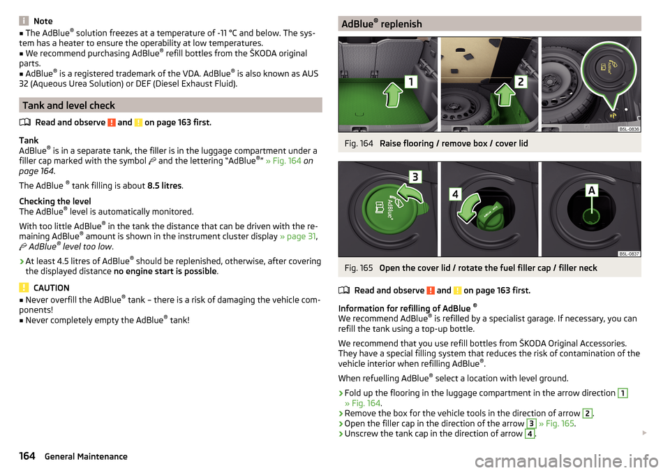
” » Fig. 164 on
page 164 .
The AdBlue ®
tank filling is about 8.5 litres.
Checking the level
The AdBlue ®
level is automatically monitored.
With too little AdBlue ®
in the tank the distance that can be driven with the re-
maining AdBlue ®
amount is shown in the instrument cluster display » page 31,
AdBlue ®
level too low .
›
At least 4.5 litres of AdBlue ®
should be replenished, otherwise, after covering
the displayed distance no engine start is possible .
CAUTION
■
Never overfill the AdBlue ®
tank – there is a risk of damaging the vehicle com-
ponents!■
Never completely empty the AdBlue ®
tank!
AdBlue ®
replenishFig. 164
Raise flooring / remove box / cover lid
Fig. 165
Open the cover lid / rotate the fuel filler cap / filler neck
Read and observe
and on page 163 first.
Information for refilling of AdBlue ®
We recommend AdBlue ®
is refilled by a specialist garage. If necessary, you can
refill the tank using a top-up bottle.
We recommend that you use refill bottles from ŠKODA Original Accessories.
They have a special filling system that reduces the risk of contamination of the
vehicle interior when refilling AdBlue ®
.
When refuelling AdBlue ®
select a location with level ground.
›
Fold up the flooring in the luggage compartment in the arrow direction
1
» Fig. 164 .
›
Remove the box for the vehicle tools in the direction of arrow
2
.
›
Open the filler cap in the direction of the arrow
3
» Fig. 165 .
›
Unscrew the tank cap in the direction of arrow
4
.
164General Maintenance
Page 171 of 232
CAUTION■If the above engine oils are not available, a different engine oil can be used in
an emergency. To prevent damage to the engine, a maximum of 0.5 litres only
of the following engine oils may be used: ■ For petrol engine models: ACEA A3/ACEA B4 or API SN, (API SM);
■ For diesel engine models: ACEA C3 or API CJ-4.
Checking the oil level
Fig. 169
Principle sketch: Dipstick
Read and observe
and on page 168 first.
The dipstick indicates the engine oil level .
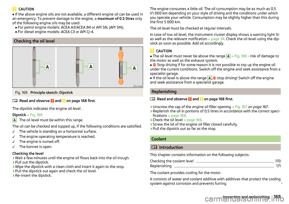
Dipstick » Fig. 169
The oil level must be within this range.
The oil can be checked and topped up, if the following conditions are satisfied. The vehicle is standing on a horizontal surface.
The engine operating temperature is reached.
The engine is turned off.
The bonnet is open.
Checking the level
›
Wait a few minutes until the engine oil flows back into the oil trough.
›
Pull out the dipstick.
›
Wipe the dipstick with a clean cloth and insert it again to the stop.
›
Pull the dipstick out again and check the oil level.
›
Re-insert the dipstick.
AThe engine consumes a little oil. The oil consumption may be as much as 0.5
l/1 000 km depending on your style of driving and the conditions under which
you operate your vehicle. Consumption may be slightly higher than this during
the first 5 000 km.
The oil level must be checked at regular intervals.
In case of low oil level, the instrument cluster display shows a warning light
as well as the relevant notification » page 34. Check the oil level using the dip-
stick as soon as possible. Add oil accordingly.
CAUTION
■ The oil level must never be above the range A » Fig. 169 - risk of damage to
the motor as well as the exhaust system.■
Stop driving if for some reason it is not possible to top up the engine oil
under the current conditions. Switch off the engine and seek assistance from a
specialist garage.
■
If the oil level is above the range
A
,
stop driving! Switch off the engine
and seek assistance from a specialist garage.
Replenishing
Read and observe
and on page 168 first.
›
Unscrew the cap of the engine oil filler opening » Fig. 167 on page 167 .
›
Replenish the oil in portions of 0.5 litres in accordance with the correct speci-
fications » page 168 .
›
Check the oil level » page 169.
›
Screw the lid of the engine oil filler closed carefully.
›
Pull the dipstick out as far as the stop.
Coolant
Introduction
This chapter contains information on the following subjects:
Checking the coolant level
170
Replenishing
171
The coolant provides cooling for the motor.
It consists of water and coolant additive with additives that protect the cooling
system against corrosion and prevents furring.
169Inspecting and replenishing
Page 173 of 232
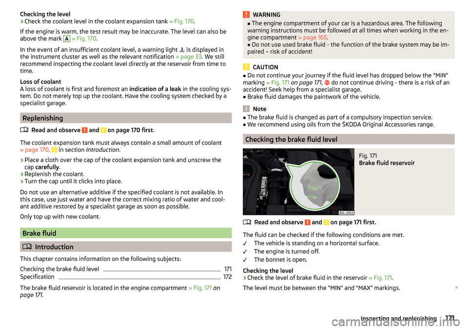
Checking the level›Check the coolant level in the coolant expansion tank » Fig. 170.
If the engine is warm, the test result may be inaccurate. The level can also be
above the mark A
» Fig. 170 .
In the event of an insufficient coolant level, a warning light
is displayed in
the instrument cluster as well as the relevant notification » page 33. We still
recommend inspecting the coolant level directly at the reservoir from time to
time.
Loss of coolant
A loss of coolant is first and foremost an indication of a leak in the cooling sys-
tem. Do not merely top up the coolant. Have the cooling system checked by a
specialist garage.
Replenishing
Read and observe
and on page 170 first.
The coolant expansion tank must always contain a small amount of coolant
» page 170, in section Introduction .
›
Place a cloth over the cap of the coolant expansion tank and unscrew the
cap carefully .
›
Replenish the coolant.
›
Turn the cap until it clicks into place.
Do not use an alternative additive if the specified coolant is not available. In
this case, use just water and have the correct mixing ratio of water and cool-
ant additive restored by a specialist garage as soon as possible.
Only top up with new coolant.
Brake fluid
Introduction
This chapter contains information on the following subjects:
Checking the brake fluid level
171
Specification
172
The brake fluid reservoir is located in the engine compartment » Fig. 171 on
page 171 .
WARNING■
The engine compartment of your car is a hazardous area. The following
warning instructions must be followed at all times when working in the en-
gine compartment » page 165.■
Do not use used brake fluid - the function of the brake system may be im-
paired – risk of accident!
CAUTION
■ Do not continue your journey if the fluid level has dropped below the “MIN”
marking » Fig. 171 on page 171 , do not continue driving - there is a risk of an
accident! Seek help from a specialist garage.■
Brake fluid damages the paintwork of the vehicle.
Note
■ The brake fluid is changed as part of a compulsory inspection service.■We recommend using oils from the ŠKODA Original Accessories range.
Checking the brake fluid level
Fig. 171
Brake fluid reservoir
Read and observe and on page 171 first.
The fluid can be checked if the following conditions are met.
The vehicle is standing on a horizontal surface.
The engine is turned off.
The bonnet is open.
Checking the level
›
Check the level of brake fluid in the reservoir » Fig. 171.
The level must be between the “MIN” and “MAX” markings.
171Inspecting and replenishing
Page 174 of 232
A slight drop in the fluid level results when driving due to normal wear-and-
tear and automatic adjustment of the brake pads.
There may be an indication of a leak in the brake system, however, if the fluid
level drops significantly within a short time or if it drops below the “MIN” mark-
ing.
Too low brake fluid level is indicated by the warning light
being shown on
the display of the instrument cluster as well as the corresponding message
» page 33 ,
Brake system .
Specification
Read and observe
and on page 171 first.
To ensure the optimal functioning of the braking system, only use a brake fluid
meeting the standard VW 501 14 (this standard meets the requirements of
FMVSS 116 DOT4).
Note
We recommend using brake fluids from the ŠKODA Original Accessories range.
Vehicle battery
Introduction
This chapter contains information on the following subjects:
Opening the cover
173
Checking the battery electrolyte level
173
Charging
174
Replacing
175
Disconnecting and reconnecting
175
Automatic load deactivation
175
The vehicle battery represents a power source for the motor to start and for
the supply of electrical consumers in the car.
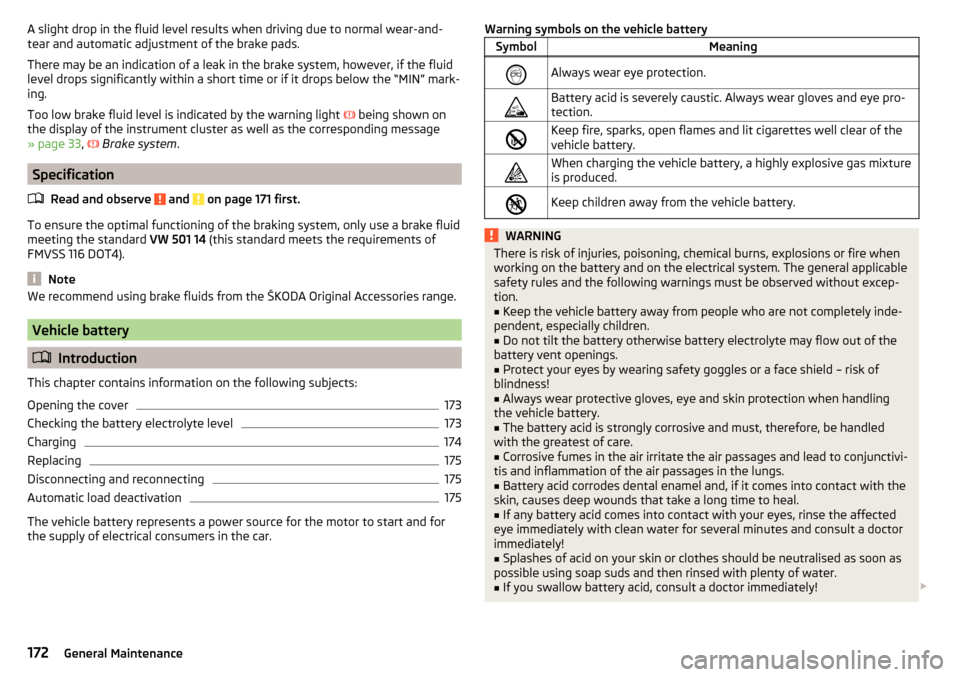
Warning symbols on the vehicle batterySymbolMeaningAlways wear eye protection.Battery acid is severely caustic. Always wear gloves and eye pro-
tection.Keep fire, sparks, open flames and lit cigarettes well clear of the
vehicle battery.When charging the vehicle battery, a highly explosive gas mixture
is produced.Keep children away from the vehicle battery.WARNINGThere is risk of injuries, poisoning, chemical burns, explosions or fire when
working on the battery and on the electrical system. The general applicable
safety rules and the following warnings must be observed without excep-
tion.■
Keep the vehicle battery away from people who are not completely inde-
pendent, especially children.
■
Do not tilt the battery otherwise battery electrolyte may flow out of the
battery vent openings.
■
Protect your eyes by wearing safety goggles or a face shield – risk of
blindness!
■
Always wear protective gloves, eye and skin protection when handling
the vehicle battery.
■
The battery acid is strongly corrosive and must, therefore, be handled
with the greatest of care.
■
Corrosive fumes in the air irritate the air passages and lead to conjunctivi-
tis and inflammation of the air passages in the lungs.
■
Battery acid corrodes dental enamel and, if it comes into contact with the
skin, causes deep wounds that take a long time to heal.
■
If any battery acid comes into contact with your eyes, rinse the affected
eye immediately with clean water for several minutes and consult a doctor
immediately!
■
Splashes of acid on your skin or clothes should be neutralised as soon as
possible using soap suds and then rinsed with plenty of water.
■
If you swallow battery acid, consult a doctor immediately!
172General Maintenance
Page 175 of 232
WARNING■The use of open flames and light should be avoided.■Smoking and radio triggering activities should be avoided.■
Never use a damaged vehicle battery – risk of explosion!
■
Never charge a frozen or thawed vehicle battery – risk of explosion and
chemical burns!
■
Replace a frozen vehicle battery.
■
Never jump-start vehicle batteries with an electrolyte level that is too low
– risk of explosion and caustic burns.
CAUTION
■ Improper handling of the vehicle battery may cause damage.■Ensure that battery acid does not come into contact with the bodywork – risk
of damage to the paintwork.■
If the vehicle has not been driven for more than 3 to 4 weeks, the battery will
discharge. Prevent the battery from discharging by disconnecting the battery's
negative terminal
or continuously charging the battery with a very low
charging current.
■
Do not place the battery in direct daylight in order to protect the vehicle bat-
tery housing from the effects of ultra-violet light.
■
If the vehicle is frequently used for making short trips, the vehicle battery
will not have time to charge up sufficiently and may discharge.
Note
■ We recommend having all work on the vehicle battery carried out by a spe-
cialist garage.■
You should replace batteries older than 5 years.
Opening the coverFig. 172
Polyester vehicle battery cover / plastic vehicle battery cover
Read and observe
and on page 172 first.
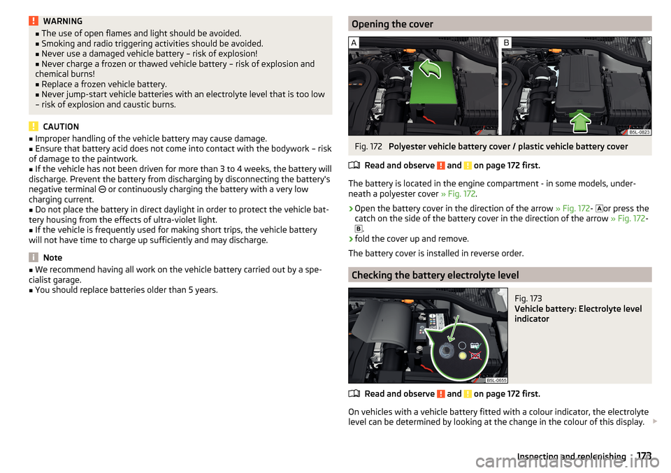
The battery is located in the engine compartment - in some models, under-
neath a polyester cover » Fig. 172.
›
Open the battery cover in the direction of the arrow » Fig. 172-
or press the
catch on the side of the battery cover in the direction of the arrow » Fig. 172-
.
›
fold the cover up and remove.
The battery cover is installed in reverse order.
Checking the battery electrolyte level
Fig. 173
Vehicle battery: Electrolyte level
indicator
Read and observe and on page 172 first.
On vehicles with a vehicle battery fitted with a colour indicator, the electrolyte
level can be determined by looking at the change in the colour of this display.
173Inspecting and replenishing