window SMART FORTWO COUPE ELECTRIC DRIVE 2015 Owner's Manual
[x] Cancel search | Manufacturer: SMART, Model Year: 2015, Model line: FORTWO COUPE ELECTRIC DRIVE, Model: SMART FORTWO COUPE ELECTRIC DRIVE 2015Pages: 222, PDF Size: 5.02 MB
Page 77 of 222

;
Front right
= Rear right
? Rear left
A Front left
X Install the side rails with the respective
front end ;orA first. G
WARNING
Make sure the side rails are properly moun- ted. Otherwise the side rails could disen-
gage while driving and injure you and other
persons. X
Take one side rail and start by attaching
it to front end D.
X Make sure the seal of the side rail is
facing up at position Band is not
pinched.
X Push the side rail at rear end Cdown-
wards until it audibly engages into place twice.
X Install the side rail on the other side in
the same manner. !
Make sure the side rails are installed
correctly. Otherwise the side rails may
not function properly or may be damaged.
X Close the storage compartment cover.
X Press on the “PRESS” marking in the mid-
dle of the storage compartment cover
until it engages audibly.
X Close the tailgate. Let the tailgate lock
into place.
X Close the driver’s and passenger door.
X Open the side windows if desired.
! Make sure the storage compartment
cover is closed before closing the tail-
gate. Otherwise the tailgate could jam. Side windows
Opening and closing the side windows
Opening and closing the power windows G
WARNING
Do not keep any part of your body up against
the side window pane when opening a win-
dow. The downward motion of the pane may
pull that part of your body down between the window pane and the door frame and trap itthere. If there is a risk of entrapment,
release the switch and pull up the top of theswitch to close the window. G
WARNING
When closing the windows, make sure there
is no danger of anyone being harmed by the closing procedure.
The closing of the side windows can be
immediately stopped by releasing the
switch.
When leaving the vehicle, always remove the
key from the starter switch, take it with
you, and lock the vehicle. Do not leave chil- dren unattended in the vehicle, or with
access to an unlocked vehicle. A child’s
unsupervised access to a vehicle could Side windows
75>> Controls.
Z
Page 78 of 222

result in an accident and/or serious per-
sonal injury.
The switches for both power windows are on
the driver’s door. In addition, there is a
switch for the passenger side on the
passenger door. :
Side window driver’s door
; Side window passenger door
X Make sure the key is in starter switch
position 1.
X Opening: Press and hold the top of the
respective switch.
The corresponding side window moves
downwards until you release the switch.
X Closing: Pull and hold the top of the
respective switch.
The corresponding side window moves
upwards until you release the switch.
X Automatic opening: Press the top of the
respective switch briefly.
The corresponding side window opens
completely.
X Stopping during automatic opening:
Press or pull the top of the respective
switch again.
The corresponding side window stops
immediately. Driving and parking
Starting
G
WARNING
Make sure absolutely no objects are
obstructing the pedals’ range of motion.
Keep the driver’s footwell clear of all
obstacles. If there are any floormats* or
carpets in the footwell, make sure the ped- als still have sufficient clearance.
During sudden acceleration or braking
maneuvers, the objects could get caught
between or beneath the pedals and restrictyour ability to brake or accelerate. This
could lead to accidents and/or injury. G
WARNING
A vehicle with an electric motor produces
significantly lower noise levels than a
vehicle with a combustion engine. Other
motorists or pedestrians, especially those who are visually or hearing impaired, may
be unable to hear your vehicle while it is in
motion. This is particularly true when
driving at lower speeds and during parking
maneuvers. At all times, it is the respon-
sibility of the driver to be aware of their
surroundings, especially in these low
speed situations. Otherwise other road
users could be seriously or fatally injured.
Vehicles equipped with an Acoustic Vehi-
cle Indication* emit a certain noise. Thus,
your vehicle will be better noticed by other
road users at low speeds (Y page 48).
X Fasten the seat belt.
X Depress the brake pedal.
X Insert the key into the starter switch.
X Move the gear selector lever to position
P or N.
P or Nappears in the transmission posi-
tion indicator.
X Turn the key to starter switch position 2
(Y page 57). Hold the key until READY READY76
Driving and parking>> Controls.
* optional
Page 93 of 222
This is useful:
R if you wish to cool the interior of the
vehicle before driving
R if you wish to charge the vehicle at a
charging station/wallbox at the most
inexpensive electricity rate
With the "Air conditioning before start"
function, the vehicle interior is cooled
prior to a desired departure time.
Prerequisites:
R The doors and tailgate are closed.
R The charging cable for the high‑voltage
battery is connected to a power source
and inserted into the vehicle's power
socket.
R The high‑voltage battery has a suffi-
cient charge.
The maximum duration of "Air condition-
ing before start" is 30 minutes.
Set the air distribution of your vehicle as
follows so that the "Air conditioning
before start" function has the greatest
effect:
R in summer, to the center and side vents
R in winter, onto the windshield and side
windows
Information on air distribution can be
found on (Y page 102).
The setting of the airflow regulator has no
influence on the "Air conditioning before
start" function.
i If the programmed time is too short, the
high‑voltage battery cannot be com-
pletely charged. After setting the depar- ture time, the maximum charge level
which can be reached is then shown.
i If the high‑voltage battery is not suf-
ficiently charged and the "Air condi-
tioning before start" function is acti-
vated, the high‑voltage battery is
charged first. When a charge level of at
least 20 %has been reached, the "Air con-
ditioning before start" function is acti-
vated. This function then has priority over the charging of the high‑voltage
battery.
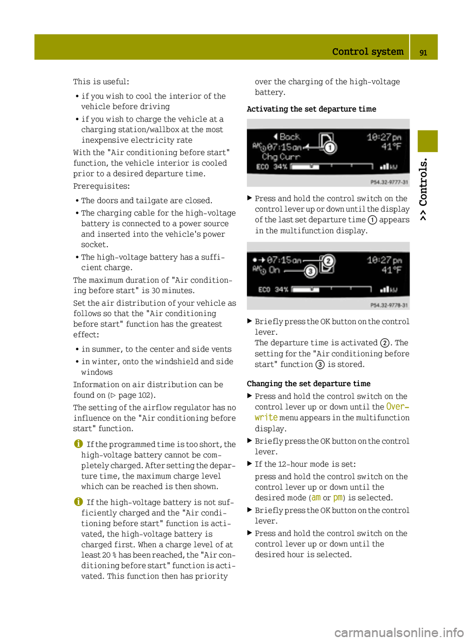
Activating the set departure time X
Press and hold the control switch on the
control lever up or down until the display
of the last set departure time :appears
in the multifunction display. X
Briefly press the OK button on the control
lever.
The departure time is activated ;. The
setting for the "Air conditioning before
start" function =is stored.
Changing the set departure time X Press and hold the control switch on the
control lever up or down until the Over‐
Over‐
write write menu appears in the multifunction
display.
X Briefly press the OK button on the control
lever.
X If the 12-hour mode is set:
press and hold the control switch on the
control lever up or down until the
desired mode (am amorpm pm) is selected.
X Briefly press the OK button on the control
lever.
X Press and hold the control switch on the
control lever up or down until the
desired hour is selected. Control system
91>> Controls. Z
Page 101 of 222

X
Press RES/+ button ;briefly.
The cruise control resumes the previ-
ously set speed.
i The last set speed stored in memory is
deleted when the drive system is
switched off.
Changing the set speed You must have set a speed prior to increas-
ing or decreasing the current speed.
i Depressing the accelerator pedal does
not deactivate the cruise control. After a brief acceleration (e.g. for passing), the
cruise control will resume the last set
speed.
Continuous adjustment
X Press and hold RES/+ button ;to
increase the speed.
or
X Press and hold SET/ −= to decrease the
speed.
X Press and hold the respective button
until the desired speed is reached.
X Release the respective button.
The new speed is stored.
Adjustment in 1 mph (Canada 1 km/h) incre- ments
X Press RES/+ button ;briefly to increase
the speed.
or X Press SET/ −= briefly to decrease the
speed.
The new speed is stored after releasing the respective button. Air conditioning with climate control
Notes
G
WARNING
Follow the recommended settings for heat-
ing and cooling given on the following pages. Otherwise the windows could fog up,
impairing visibility and endangering you
and others.
The air conditioning improves the level of
comfort when driving at high outside tem-
peratures by cooling and dehumidifying
the air.
Nearly all dust particles, pollutants, are
filtered out by an integrated particle fil-
ter before outside air enters the passenger compartment through the air distribution
system. It also operates when the air con-
ditioning is switched off and you have
switched on the blower.
The dehumidification of the air by the air
conditioner prevents the windows from
misting up when the outside air humidity
is high.
This effect can also be used to defrost the
windows. For this, make sure, in addition
to the air conditioner, that the heater is on the maximum setting.
The air conditioner only works when:
R the ignition is switched on
R the blower is switched on
R the driver's door is closed
Maximum effectiveness is achieved if you
drive with the windows closed.
If the operating temperature of the
high‑voltage battery is too high, the
high‑voltage battery is cooled by the air
conditioner. When the air conditioner
switches on, the cooling output in the vehi- cle's interior is reduced as a result. The
temperature in the vehicle's interior may
rise briefly.
If the air conditioner is not switched on,
the compressor of the air conditioner and
the vehicle's cooling fan are switched on
automatically. This cools the high‑voltage
battery but not the vehicle's interior. When
the high‑voltage battery reaches the nom-
inal temperature again, the air condi-
tioner switches off automatically. Air conditioning with climate control
99>> Controls. Z
Page 103 of 222

Control panel
:
Air volume control
; Air conditioning switch
= Rear window defroster switch
? Air recirculation switch
A Temperature control
B Air distribution control Switching on/off
Control panel (Y page 101).
X Make sure the ignition is switched on.
X Switching on: Push air volume control :
to level 1or higher.
X Press air conditioning switch ;.
The indicator lamp in air conditioning
switch ;comes on.
X Switching off: Press air conditioning
switch ;once more.
The indicator lamp in air conditioning
switch ;goes out.
i The stored status is restored, if you
switch on the ignition again. Setting the temperature
Control panel (Y page 101).
i You should raise or lower the tempera-
ture setting in small increments, pref-
erably starting at 70¦ (21¥).X
Increasing or decreasing: Push temper-
ature control Aup or down. Adjusting air vents
G
WARNING
When operating the heating or air condi-
tioning with climate control, the air that
enters the passenger compartment through
the air vents can be very hot or very cold
(depending on the set temperature). This
may cause burns or frostbite on unprotected skin in the immediate area of the air vents.
Always keep sufficient distance between
unprotected parts of the body and the air
vents. If necessary, use the air distribu-
tion control to direct the air to air vents in the vehicle interior that are not in the
immediate area of unprotected skin.
To make sure the heating or air condition-
ing with climate control works properly,
please observe the following:
R Keep the air intake grill free from
deposits, e.g. ice or snow, to ensure that Air conditioning with climate control
101>> Controls. Z
Page 104 of 222

fresh air can flow freely into the vehicle
interior.
R Do not obstruct air vents or ventilation
grilles in the vehicle interior.
i For draft-free ventilation, move the
sliders for the center air vents and side air vents to the middle position.
Center air vents :
Left center air vent, adjustable
; Right center air vent, adjustable
X Adjusting: Turn slider :or; to the
left, right, up, or down.
X Opening: Turn slider :or; inwards
towards the center console.
X Closing: Turn slider :or; fully out-
wards towards the side window.
Side air vents Side air vents on driver’s side illustrated as
example
: Left side air vent, adjustable
; Left side defroster air vent, fixed X
Adjusting: Turn slider :to the left,
right, up, or down.
X Opening: Turn slider :inwards towards
the center console.
X Closing: Turn slider :fully outwards
towards the side window. Adjusting air distribution
Symbol Function
z
Directs air to the windshield
and side windows
O
Directs air to the footwells
and air distribution is
reduced at the center and side
air vents P
Directs air through the center
and side air vents i
You can also turn the air distribution
control to a position between two sym-
bols.
Control panel (Y page 101).
X Turn air distribution control Bto the
desired symbol.
The air distribution is controlled
depending on the position of the air dis- tribution control. Adjusting air volume
The air volume is controlled depending on
the blower speed selected. Five blower
speeds are available. 0
Off
1
Slow
2
Medium
3
High/defrosting
4
Maximum102
Air conditioning with climate control>> Controls.
Page 105 of 222

X
Increasing or decreasing: Push air vol-
ume control :up or down. Defrosting
G
WARNING
Never drive with iced up or fogged win-
dows. Visibility will be significantly
impaired. Impaired visibility could
endanger yourself and others. This may
prevent you from observing the traffic con- ditions, thereby causing an accident.
The best defrosting of windows is achieved
if the ice is completely removed from the
windows manually with an ice scraper
before driving off.
Also use the "Air conditioning before
start" function (Y page 90).
Control panel (Y page 101).
X Switching on: Push air volume control :
to level 3.
X Turn air distribution control Bto posi-
tion z.
X Push temperature control Afully up. Rear window defroster
The rear window defroster serves to de-ice
the rear window quickly and clear the view if the rear window is fogged.
The rear window defroster uses a large
amount of power. To keep battery drain to a
minimum, switch off the rear window
defroster as soon as the rear window is
clear. The rear window defroster is auto-
matically deactivated after approximately 10 minutes of operation. X
Make sure the key is in starter switch
position 1.
X Switching on: Press rear window
defroster switch :.
The indicator lamp in rear window
defroster switch :comes on.
X Switching off: Press rear window
defroster switch :once more.
The indicator lamp in rear window
defroster switch :goes out. Air recirculation mode
Switch to air recirculation mode to prevent unpleasant odors from entering the vehicle
from the outside (e.g. before driving
through a tunnel). This setting cuts off the
intake of outside air and recirculates the
air in the passenger compartment. G
WARNING
When the air recirculation mode is
switched on, windows can fog on the inside immediately. Fogged windows impair vis-
ibility, endangering you and others. If the
windows begin to fog on the inside, switch- ing off the air recirculation mode imme-
diately should clear interior window fog-
ging. If interior window fogging persists,
make sure the air conditioning is switched on, turn air distribution control Bto
position zand increase the air volume
using air volume control :.
Control panel (Y page 101). Air conditioning with climate control
103>> Controls. Z
Page 111 of 222
.
The handling characteristics of a fully
loaded vehicle depend greatly on t")
label which can be found on the driver’s
door B‑pillar.
For more information, see “Loading the
vehicle” (Y page 133).
The handling characteristics of a fully
loaded vehicle depend greatly on the load
distribution. It is therefore recommended
to load the vehicle with the heaviest items being placed towards the front of the vehi-cle.
Please pay attention to and comply with thefollowing instructions when loading the
vehicle and transporting cargo:
R Always place items being carried
against seat backrests, and fasten them
as securely as possible.
R The heaviest portion of the cargo should
always be kept as low as possible against
seat backrests.
R Do not stack loads higher than the top
edge of the head restraints.
R Make sure no luggage/cargo items can get
above or next to the driver’s and/or
passenger seat into the passenger com-
partment.
R Make sure luggage/cargo is properly
secured.
R Always use, if so equipped, cargo net*
when transporting cargo.
Do not carry any unnecessary weight in the
vehicle. This increases vehicle weight,
which results in increased energy con-
sumption. Useful features
Sun visors
The sun visors protect you from sun glare
while driving. Glare through the windshield
X
Swing sun visor :down.
Glare through a side window X
Swing sun visor :down.
X Disengage sun visor :from mount-
ing ;.
X Pivot sun visor :to the side. Sun screen*
The sun screen provides protection from
sun rays and from heat generated by the
panorama roof*.
The sun screen can be adjusted to any
desired position. X
Opening or closing: Move sun screen:
forward or backward using the handle. Useful features
109>> Controls.
* optional Z
Page 128 of 222
.
X Perform a visual check of the fluid")
Checking coolant level
X
Allow the coolant to cool down for at least
30 minutes.
X Remove the service flap and insert it on
the front of the vehicle (Y page 123).
X Perform a visual check of the fluid level
in coolant reservoir ;.
The coolant level must be between the
markings MAX and MIN.
X If necessary, add coolant.
Adding coolant X
Cover pressure cap :with a rag.
X Slowly turn pressure cap :approx-
imately Öturn counterclockwise to
release any excess pressure.
X Continue turning pressure cap :coun-
terclockwise and remove it.
X Add coolant as required. The coolant
level may not exceed the maximum filling level.
X Reinstall and tighten pressure cap :.
X Remount the service flap and close it
(Y page 123). Windshield/rear window washer system
Both the windshield and the rear window 6
washer are supplied from the windshield
washer reservoir. The recommended minimum filling level is
1.06 US qt (1.0 l).
X Remove the service flap and insert it on
the front of the vehicle (Y page 123).
The windshield washer reservoir is located
in the front compartment on the driver’s
side. G
WARNING
Windshield washer concentrate is highly
flammable. Fire, naked flames and smoking
are prohibited when windshield washer
concentrate is being handled.
X Use a windshield washer concentrate
labeled for summer and water for tem-
peratures above freezing point.
X Use a windshield washer concentrate
labeled for winter and water for temper-
atures below freezing point.
! Always use a windshield washer concen-
trate labeled for winter where tempera-
tures may fall below freezing point.
Failure to do so could result in damage to
the washer system/reservoir.
X Premix the windshield washer fluid in a
suitable container.
Observe mixing ratios depending on the
outside temperature (Y page 218).
X Use the tab to pull cap :upwards.
X Refill the windshield washer reservoir.
6 Coupé only. 126
Front compartment>> Operation.
Page 145 of 222

The TIN is a unique identifier which facil-
itates efforts by tire manufactures to
notify purchasers in recall situations or
other safety matters concerning tires and
gives purchasers the means to easily iden- tify such tires.
The TIN is comprised of “Manufacturer’s
identification mark” ;, “Tire size”=,
“Tire type code” ?, and “Date of manufac-
ture” A.
i For illustration purposes only. Actual
data on tires are specific to each vehicle and may vary from data shown in above
illustration.
DOT (Department of Transportation) Tire branding symbol
:which denotes the
tire meets requirements of the U.S. Depart- ment of Transportation.
Manufacturer’s identification mark Manufacturer’s identification mark
;
denotes the tire manufacturer.
New tires have a mark with two symbols.
Retreaded tires have a mark with four sym-
bols. For more information on retreaded
tires (Y page 127).
Tire size Code
=indicates the tire size. Tire type code Tire type code
?may, at the option of the
manufacturer, be used as a descriptive
code for identifying significant charac-
teristics of the tire.
Date of manufacture Date of manufacture
Aidentifies the week
and year of manufacture.
The first two figures identify the week,
starting with “01” to represent the first
full week of the calendar year. The second
two figures represent the year.
For example, “3202” represents the 32nd
week of 2002. Tire ply material
i
For illustration purposes only. Actual
data on tires are specific to each vehicle and may vary from data shown in above
illustration.
This marking tells you about the type of
cord and number of plies in the sidewall :
and under the tread ;. Tire and loading terminology
Accessory weight The combined weight (in excess of those
standard items which may be replaced) of
transmission, power steering, power
brakes, power windows, power seats, radio, Tires and wheels
143>> Operation. Z