filter SSANGYONG KORANDO 1997 Service User Guide
[x] Cancel search | Manufacturer: SSANGYONG, Model Year: 1997, Model line: KORANDO, Model: SSANGYONG KORANDO 1997Pages: 2053, PDF Size: 88.33 MB
Page 36 of 2053
1B1 -- 4 M162 ENGINE MECHANICAL
D AEW OO M Y_2000
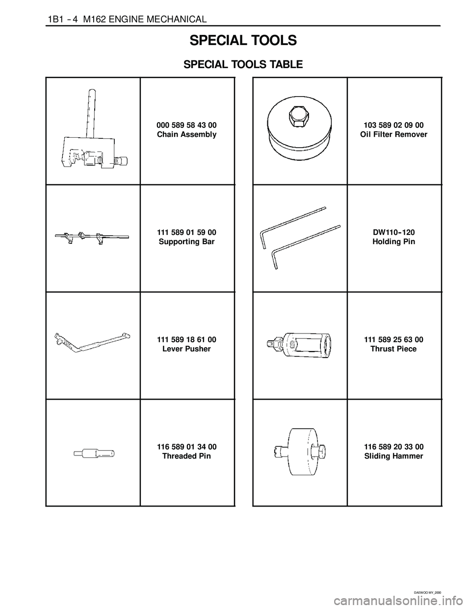
SPECIAL TOOLS
SPECIAL TOOLS TABLE
000 589 58 43 00
Chain Assembly
111 589 01 59 00
Supporting Bar
111 589 18 61 00
Lever Pusher
116 589 01 34 00
Threaded Pin
103 589 02 09 00
Oil Filter Remover
DW110 -- 120
Holding Pin
111 589 25 63 00
Thrust Piece
116 589 20 33 00
Sliding Hammer
Page 40 of 2053
1B1 -- 8 M162 ENGINE MECHANICAL
D AEW OO M Y_2000
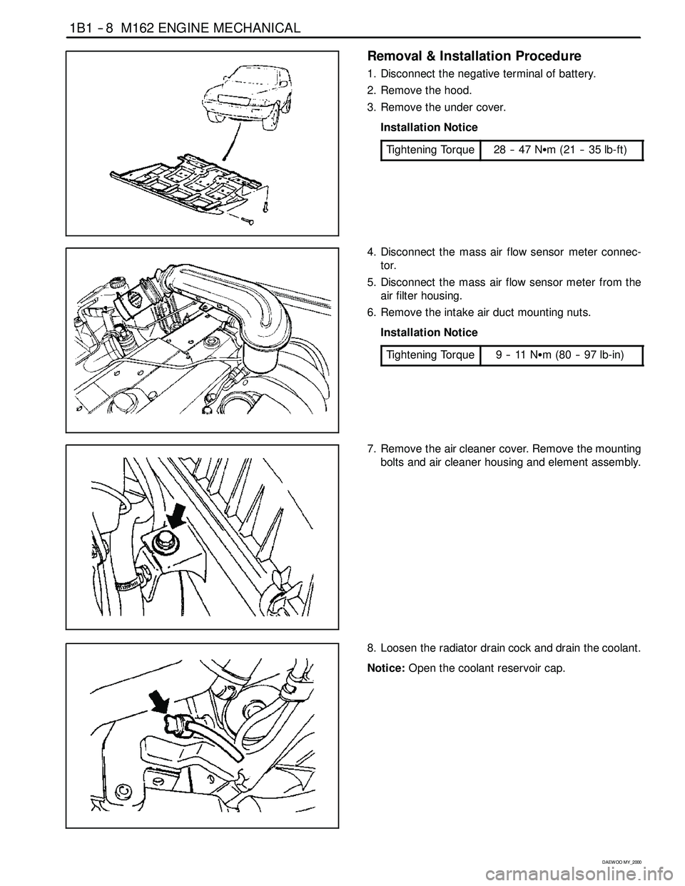
Removal & Installation Procedure
1. Disconnect the negative terminal of battery.
2. Remove the hood.
3. Remove the under cover.
Installation Notice
Tightening Torque
28 -- 47 NSm (21 -- 35 lb-ft)
4. Disconnect the mass air flow sensor meter connec-
tor.
5. Disconnect the mass air flow sensor meter from the
air filter housing.
6. Remove the intake air duct mounting nuts.
Installation Notice
Tightening Torque
9--11NSm (80 -- 97 lb-in)
7. Remove the air cleaner cover. Remove the mounting
bolts and air cleaner housing and element assembly.
8. Loosen the radiator drain cock and drain the coolant.
Notice:Open the coolant reservoir cap.
Page 46 of 2053
1B1 -- 14 M162 ENGINE MECHANICAL
D AEW OO M Y_2000
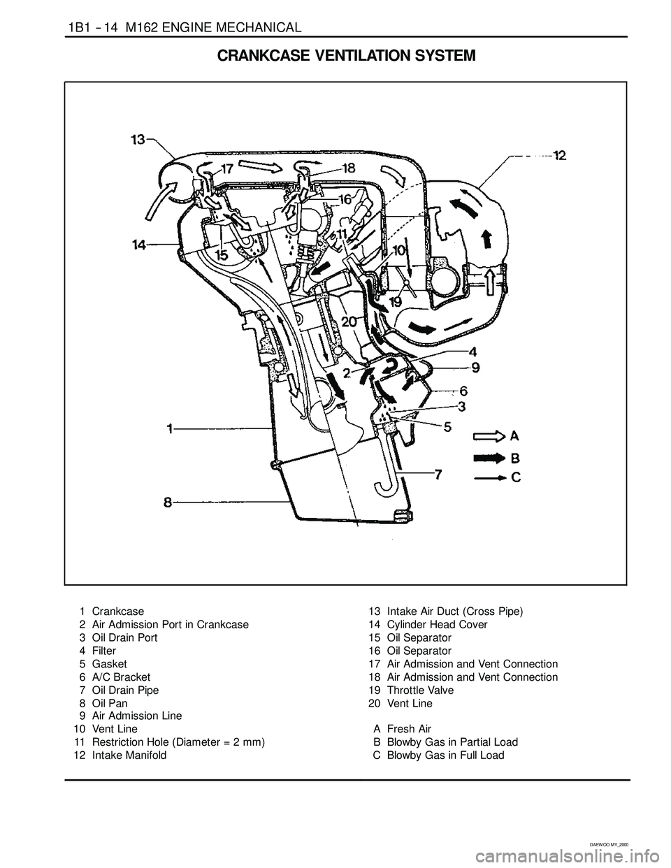
CRANKCASE VENTILATIONSYSTEM
1 Crankcase
2 Air Admission Port in Crankcase
3 Oil Drain Port
4 Filter
5 Gasket
6 A/C Bracket
7 Oil Drain Pipe
8OilPan
9 Air Admission Line
10 Vent Line
11 Restriction Hole (Diameter = 2 mm)
12 Intake Manifold13 Intake Air Duct (Cross Pipe)
14 Cylinder Head Cover
15 Oil Separator
16 Oil Separator
17 Air Admission and Vent Connection
18 Air Admission and Vent Connection
19 Throttle Valve
20 Vent Line
A Fresh Air
B Blowby Gas in Partial Load
C Blowby Gas in Full Load
Page 113 of 2053
M162 ENGINE MECHANICAL 1B1 -- 87
D AEW OO M Y_2000
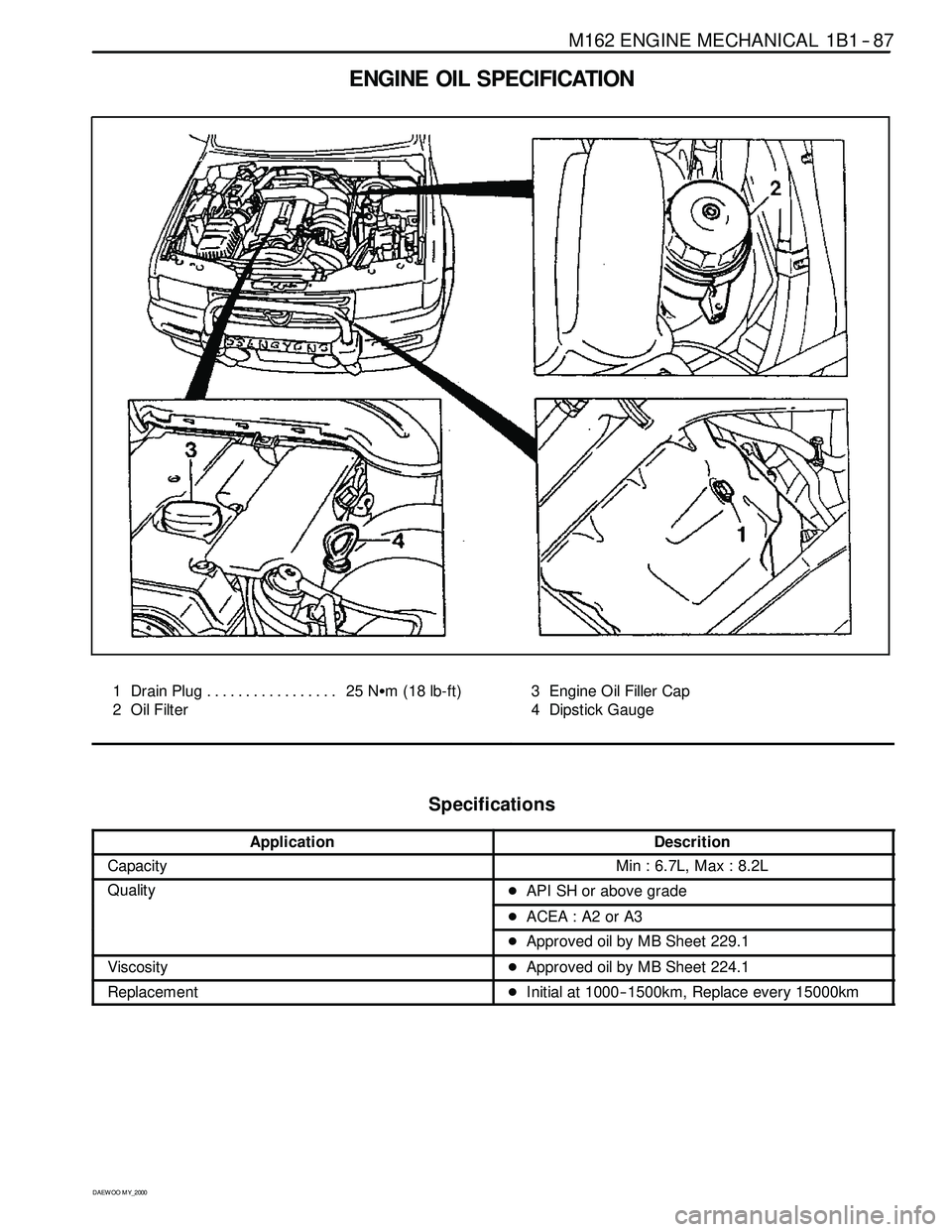
ENGINE OIL SPECIFICATION
1 Drain Plug 25 NSm (18 lb-ft) .................
2 Oil Filter3 Engine Oil Filler Cap
4 Dipstick Gauge
Specifications
ApplicationDescrition
CapacityMin : 6.7L, Max : 8.2L
QualityDAPI SH or above gradey
DACEA : A2 or A3
DApproved oil by MB Sheet 229.1
ViscosityDApproved oil by MB Sheet 224.1
ReplacementDInitial at 1000-- 1500km, Replace every 15000km
Page 115 of 2053

M162 ENGINE MECHANICAL 1B1 -- 89
D AEW OO M Y_2000
Oil Circulation
1OilPump
2 Oil Gallery (to oil filter)
3 Oil Filter
4 Oil Pressure Switch
5 Main Oil Gallery
6 Cylinder Head Closing Cover
7 Oil Gallery (At Chain Tensioner)
8 Oil Non-- return Valve
9 Chain Tensioner
10 Vent (Chain Tensioner)
11 Front Closing Cover (φ17 mm)
12 Oil Gallery (Perpendicular to The Shaft)
13 Ball (φ6 mm)
14 Oil Spray Nozzle (Timing Chain)
15 Oil Gallery (At Cylinder Head)
16 Ball (φ15mm)
17 Oil Restriction Inner (φ4mm)
18 Oil Supply (To Exhaust Camshaft)19 Oil Supply (To Intake Camshaft)
20 Oil Supply (To Exhaust Camshaft Bearing)
21 Oil Supply (To Intake Camshaft Bearing)
22 Oil Gallery (Oil Supply to Exhaust Valve Tappet)
23 Oil Gallery (Oil Supply to Exhaust Valve Tappet)
24 Camshaft Closing Cover
25 Ball (φ8 mm)
26 Screw Plug
27 Camshaft Adjuster
28 Front Closing Cover (Intake Camshaft)
29 Front Treaded Bushing (Exhaust Camshaft)
30 Valve tappet
a Oil Gallery (From Oil Pump to Oil Filter)
b Main Oil Gallery
c Oil Return Line (Oil Returns to the Oil Pan
when Replacing the Filter Element)
Page 116 of 2053

1B1 -- 90 M162 ENGINE MECHANICAL
D AEW OO M Y_2000
ENGINE OIL AND OIL FILTER
ELEMENT
Tools Required
103 589 02 09 00 Oil Filter Remover
Replacement Procedure
1. Install the oil filter remover 103 589 02 09 00 on the oil
filter cover.
Notice:Make the screw cover removable by tightening
the bolt at the side of the oil filter remover 103 589 02 09
00.
2. Install the wrench to the upper bolt in the oil filter re-
mover 103 589 02 09 00 and remove the oil cover by
turning it.
3. Remove the oil filter element.
Notice:Work with a cloth under the vehicle when re-
moving the oil filter element not to drain the oil.
4. Remove the drain plug (arrow) and drain the engine
oil.
Notice:Leave the oil filler cap open to ease theengine
oil discharge.
5. Tighten the engine oil drain plug after cleaning it.
Installation Notice
Tightening Torque
25 NSm (18 lb-ft)
Replace the seal washer with new one.
6. Replace the O -- ring in the oil filter cover with new one.
Notice:Apply the engine oil to the O -- ring.
7. Insert new oil filter element into the oil filter housing.
Page 117 of 2053
M162 ENGINE MECHANICAL 1B1 -- 91
D AEW OO M Y_2000
8. Temporarily tighten the oil filter cover. Install the oil
filter remover 103 589 02 09 00, and then complete-
ly tighten it.
Installation Notice
Tightening Torque
25 NSm (18 lb-ft)
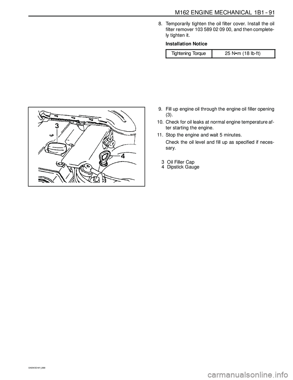
9. Fill up engine oil through the engine oil filler opening
(3).
10. Check for oil leaks at normal engine temperature af-
ter starting the engine.
11. Stop the engine and wait 5 minutes.
Check the oil level and fill up as specified if neces-
sary.
3 Oil Filler Cap
4 Dipstick Gauge
Page 118 of 2053

1B1 -- 92 M162 ENGINE MECHANICAL
D AEW OO M Y_2000
OIL FILTER
Preceding Work: Removal of starter motor
Removal of upper intake manifold
1 Coolant Line
2 O -- ring Replace............................
3 Clip
4Hose5Bolt 25NSm (18 lb-ft) ......................
6 Oil Filter
7 Gasket Replace...........................
Page 119 of 2053

M162 ENGINE MECHANICAL 1B1 -- 93
D AEW OO M Y_2000
Removal & Installation Procedure
1. Drain the coolant from the crank case.
2. Remove the each coolant line and hose.
3. Remove the oil filter bolt and then remove the oil filter.
Installation Notice
Tightening Torque
25 NSm (18 lb-ft)
Notice:Replace the oil filter gasket.
4. Installation should follow the removal procedure in
the reverse order.
5. Check engine oil level.
6. Run the engine at idle and check the engine for leaks.
Page 164 of 2053

D AEW OO M Y_2000
SECTION 1F1
ENGINE CONTROLS
CAUTION: Disconnect the negative battery cable before removing or installing any electrical unit or when a
tool or equipment could easily come in contact with exposed electrical terminals. Disconnecting this cable
will help prevent personal injury and damage to the vehicle. The ignition must also be in LOCK unless other -
wise noted.
TABLE OF CONTENTS
Engine and ECM Problem Check Report 1F1 -- 2....
Specifications 1F1 -- 3............................
Engine Data Display Table 1F1 -- 3.................
Fastener Tightening Specifications 1F1 -- 4..........
Fuel System Specification 1F1 -- 5.................
Temperature vs Resistance 1F1 -- 5................
Special Tools and Equipment 1F1 -- 6..............
Special Tools Table 1F1 -- 6.......................
Schematic and Routing Diagrams 1F1 -- 7..........
ECM Wiring Diagram
(3.2L DOHC -- MSE 3.62S) 1F1 -- 7..............
Diagnosis 1F1 -- 14................................
Failure Code Diagnosis 1F1 -- 14.....................
Clearing Failure Codes 1F1 -- 14...................
Failure Codes Table 1F1 -- 14.....................
Ignition System 1F1 -- 18...........................
Ignition Coil 1F1 -- 20.............................
Crankshaft Position (CKP) Sensor 1F1 -- 22.........
Camshaft Position (CMP) Sensor 1F1 -- 26..........
Camshaft Actuator 1F1 -- 30......................
Knock Sensor (KS) 1F1 -- 32......................
Spark Plug 1F1 -- 34.............................
System Voltage 1F1 -- 38.........................
Ignition Switch 1F1 -- 39..........................
Fuel System 1F1 -- 40..............................
Fuel Pump 1F1 -- 42.............................
Fuel Injector 1F1 -- 46............................
Purge Control Valve 1F1 -- 50.....................
Fuel Rail 1F1 -- 52...............................
Fuel Pressure Regulator 1F1 -- 54.................
Induction System 1F1 -- 56..........................
Throttle Valve Actuator 1F1 -- 56...................
Hot Film Air Mass (HFM) Sensor 1F1 -- 60..........
Engine Coolant Temperature (ECT) Sensor 1F1 -- 64.
Accelerator Pedal Module 1F1 -- 68................
Clutch Switch 1F1 -- 71...........................Cooling Fan 1F1 -- 72............................
A/C Compressor Relay 1F1 -- 73...................
Cruise Control Switch 1F1 -- 74....................
Traction Control System (TCS) 1F1 -- 75............
Resonance Flap 1F1 -- 76.........................
Stop Lamp Switch 1F1 -- 77.......................
Engine RPM 1F1 -- 78............................
Exhaust System 1F1 -- 79...........................
Catalytic Converter 1F1 -- 79......................
Oxygen Sensor 1F1 -- 80.........................
Engine Control Module 1F1 -- 86.....................
Serial Data Communication 1F1--88...............
Internal Failure 1F1 -- 90..........................
Electronic Throttle Controller Safety
Malfunction 1F1 -- 92...........................
Immobilizer 1F1 -- 94.............................
Maintenance and Repair 1F1 -- 95..................
On -- Vehicle Service 1F1 -- 95........................
Discharging the Pressure in Fuel System 1F1 -- 95...
Fuel Pump 1F1 -- 95.............................
Fuel Filter 1F1 -- 96..............................
Fuel Tank 1F1 -- 97..............................
Fuel Pressure Regulator 1F1 -- 98.................
Fuel Rail and Injector 1F1 -- 99....................
Engine Coolant Temperature Sensor 1F1 -- 100......
Throttle Body (Integrated with the
Actuator) 1F1 -- 101............................
Hot Film Air Mass (HFM) Sensor 1F1 -- 102.........
Knock Sensor 1F1 -- 102..........................
Pedal Position Sensor 1F1 -- 103...................
Oxygen Sensor 1F1 -- 103........................
Purge Control Valve 1F1 -- 104....................
Canister 1F1 -- 104...............................
Camshaft Position Sensor 1F1 -- 104...............
Crankshaft Position Sensor 1F1 -- 105..............
Engine Control Module 1F1 -- 105..................