Idle control SSANGYONG KORANDO 1997 Service Owner's Manual
[x] Cancel search | Manufacturer: SSANGYONG, Model Year: 1997, Model line: KORANDO, Model: SSANGYONG KORANDO 1997Pages: 2053, PDF Size: 88.33 MB
Page 278 of 2053

1G1 -- 10 M162 ENGINE INTAKE & EXHAUST
D AEW OO M Y_2000
Function Description
A pneumatically actuated resonance flap (5) is located
on the intake manifold, and will be opened and closed by
load, which operates resonance flap according to engine
and controlled by ECU and rpm.
1. Resonance flap closed (at idle/partial load : less
than 3,800/rpm)
The switch valve (7) will be adjusted by ECU and res-
onance flapwill be closed. By increasing air flow pas-
sage through dividing intaking air flow toward both air
collection housing (8). This leads to a signficant in-
crease in the torque in the lower speed range.
2. Resonance flap open (at full load:over 3,800/rpm)
The switch valve (7) will not be adjusted by ECU and
resonance flap (5) will beopen. The colllected air in
the air collection housing (8)will not be divided and
intaking air passage will be shorten.
Page 286 of 2053

1A2 -- 2 GENERAL ENGINE INFORMATION
D AEW OO M Y_2000
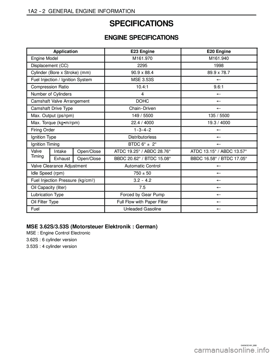
SPECIFICATIONS
ENGINE SPECIFICATIONS
ApplicationE23 EngineE20 Engine
Engine ModelM161.970M161.940
Displacement (CC)22951998
Cylinder (Bore x Stroke)(mm)90.9 x 88.489.9 x 78.7
Fuel Injection / Ignition SystemMSE 3.53S←
Compression Ratio10.4:19.6:1
Number of Cylinders4←
Camshaft Valve ArrangementDOHC←
Camshaft Drive TypeChain-- Driven←
Max. Output (ps/rpm)149 / 5500135 / 5500
Max. Torque (kgSm/rpm)22.4 / 400019.3 / 4000
Firing Order1--3--4--2←
Ignition TypeDistributorless←
Ignition TimingBTDC 6°±2°←
Va lv e
Tii
IntakeOpen/CloseATDC 19.25°/ ABDC 28.76°ATDC 13.15°/ ABDC 13.57°
Tim in gExhaustOpen/CloseBBDC 20.62°/ BTDC 15.08°BBDC 16.58°/ BTDC 17.05°
Valve Clearance AdjustmentAutomatic Control←
Idle Speed (rpm)750±50←
Fuel Injection Pressure (kg/cm@)3.2 -- 4.2←
Oil Capacity (liter)7.5←
Lubrication TypeForced by Gear Pump←
Oil Filter TypeFull Flow with Paper Filter←
FuelUnleaded Gasoline←
MSE 3.62S/3.53S (Motorsteuer Elektronik : German)
MSE : Engine Control Electronic
3.62S : 6 cylinder version
3.53S : 4 cylinder version
Page 424 of 2053

1F2 -- 2 M161 ENGINE CONTROLS
D AEW OO M Y_2000
ENGINE AND ECM PROBLEM CHECK REPORT
VEHICLE AND CUSTOMER INFORMATION
Date problem Occurred
Customer NameVehicle Model
Driver NameVIN
Purchase dateEngine Model
License No.MileageKm
miles
MIL INFORMATION
Condition of MILjRemains onjSometimes illuminatesjDoes not illuminate
DTC inspection
(if available)jNormaljMalfunction code(s) (code )
jFreezed frame data ( )
PROBLEM DESCRIPTION
jEngine Does Not StartjNo crankingjNo initial combustionjNo complete combustion
jHard to StartjSlow cranking
jOthers
jPoor IdlingjIncorrect first IdlejAbnormal idle rpmjHigh (rpm)jLow (rpm)
jIdling UnstablejOthers
jPoor DriveabilityjHesitationjBack firejMuffler explosion (after-burning)
jSurgingjKnockingjPoor performancejOther
jEngine StalljSoon after startingjAfter accelerator pedal depressed
jAfter accelerator pedal releasedjDuring A/C operation
jShifting from N to D or D to N
jAt full steeringjOthers
jOthers
CONDITION WHEN PROBLEM OCCURS
Problem FrequencyjConstantjIntermittent (times per day/month)jOnce onlyjOthers
WeatherjFinejCloudyjRainyjSnowyjVarious/Others
Ambient TemperaturejHotjWar mjCooljCold (approx.____°F/____°C)
PlacejHighwayjSuburbsjInner CityjUphilljDownhill
jRough RoadjOthers
Engine TemperaturejColdjWarming UpjBefore warming upjAfter warm-up
jAny temp.jOthers
Engine OperationjStartingjJust after starting (min.)jIdlingjRacingjDriving
jConstant speedjAccelerationjDeceleration
jA/C switch ON/OFFjOther
Page 425 of 2053

M161 ENGINE CONTROLS 1F2 -- 3
D AEW OO M Y_2000
SPECIFICATIONS
ENGINE DATA DISPLAY TABLE
ParameterUnitVa l u e
Engine Coolant Temp.°Cgreater than 95_Cafterwarmup
Intake Air Temp.°C-- 40 ~ 130_C (varies with ambient
temp. or engine mode)
Engine RPMrpm700±50 (P/N), 600±50 (D)
Regular RPMrpm700±50 (P/N), 600±50 (D)
Engine Load%18 ~ 25 %
Mass Air Flow MeterKg/h16 ~ 25 Kg/h
Throttle Position Angle_TA0_TA(upto100_TA at the wide
open throttle)
Spark Advance_CA8_CA (6 ~ 9_CA)
Indicated Engine TorqueNmVaries with engine condition
Injection Timems3~5ms
Battery VoltageV13.5 ~ 14.1 v (engine running)
Front Axle SpeedKm/h0~265Km/h
Rear Axle SpeedKm/h0~265Km/h
Accel. Pedal Position 1V0.4~4.8V
Accel. Pedal Position 2V0.2~2.4V
Throttle Position 1V0.3~4.6V
Throttle Position 2V0.3~4.6V
Fuel Integrator0.8 ~ 1.2
Oxygen Sensormv100 ~ 900 mv
A/C S/W Condition1=ON/0=OFF--
Full Load State1=ON/0=OFF--
Shift Gear State (A/T)1=ON/0=OFF--
A/CControlState1=ON/0=OFF--
Clutch Switch (M/T)1=ON/0=OFF--
Cam Actuator State1=ON/0=OFF--
Knocking Control1=ON/0=OFF--
Protect Mission1=ON/0=OFF--
Purge Control Valve1=ON/0=OFF--
Lambda Function1=ON/0=OFF--
Catalyst Heating1=ON/0=OFF--
Overrun Fuel Cut1=ON/0=OFF--
Full Fuel Cut1=ON/0=OFF--
Brake Switch1=ON/0=OFF--
Cruise Control Status1=ON/0=OFF--
* Condition : Warmed up, idle, P/N or neutral
Page 437 of 2053

M161 ENGINE CONTROLS 1F2 -- 15
D AEW OO M Y_2000
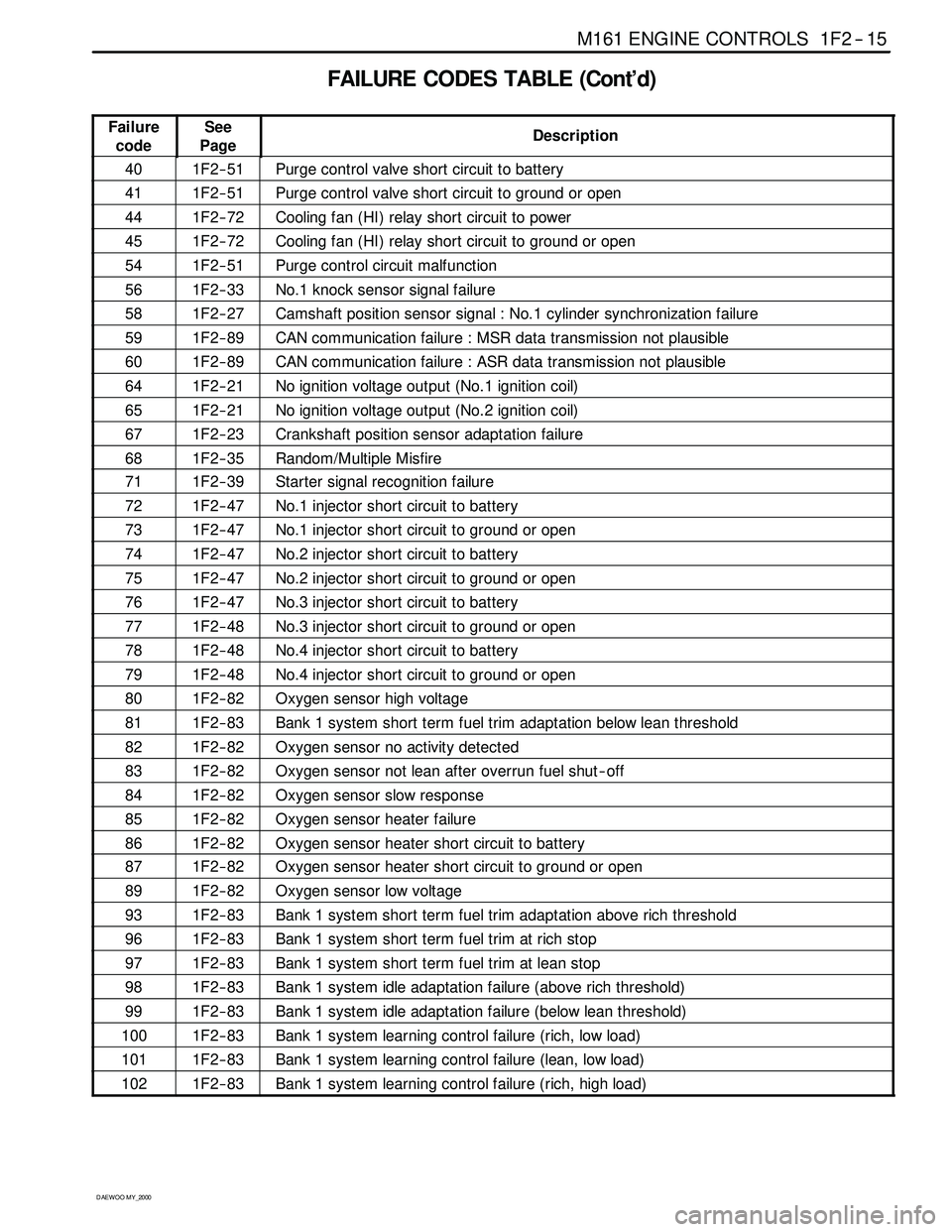
FAILURE CODES TABLE (Cont’d)
Failure
codeSee
PageDescription
401F2 -- 51Purge control valve short circuit to battery
411F2 -- 51Purge control valve short circuit to ground or open
441F2 -- 72Cooling fan (HI) relay short circuit to power
451F2 -- 72Cooling fan (HI) relay short circuit to ground or open
541F2 -- 51Purge control circuit malfunction
561F2 -- 33No.1 knock sensor signal failure
581F2 -- 27Camshaft position sensor signal : No.1 cylinder synchronization failure
591F2 -- 89CAN communication failure : MSR data transmission not plausible
601F2 -- 89CAN communication failure : ASR data transmission not plausible
641F2 -- 21No ignition voltage output (No.1 ignition coil)
651F2 -- 21No ignition voltage output (No.2 ignition coil)
671F2 -- 23Crankshaft position sensor adaptation failure
681F2 -- 35Random/Multiple Misfire
711F2 -- 39Starter signal recognition failure
721F2 -- 47No.1 injector short circuit to battery
731F2 -- 47No.1 injector short circuit to ground or open
741F2 -- 47No.2 injector short circuit to battery
751F2 -- 47No.2 injector short circuit to ground or open
761F2 -- 47No.3 injector short circuit to battery
771F2 -- 48No.3 injector short circuit to ground or open
781F2 -- 48No.4 injector short circuit to battery
791F2 -- 48No.4 injector short circuit to ground or open
801F2 -- 82Oxygen sensor high voltage
811F2 -- 83Bank 1 system short term fuel trim adaptation below lean threshold
821F2 -- 82Oxygen sensor no activity detected
831F2 -- 82Oxygen sensor not lean after overrun fuel shut -- off
841F2 -- 82Oxygen sensor slow response
851F2 -- 82Oxygen sensor heater failure
861F2 -- 82Oxygen sensor heater short circuit to battery
871F2 -- 82Oxygen sensor heater short circuit to ground or open
891F2 -- 82Oxygen sensor low voltage
931F2 -- 83Bank 1 system short term fuel trim adaptation above rich threshold
961F2 -- 83Bank 1 system short term fuel trim at rich stop
971F2 -- 83Bank 1 system short term fuel trim at lean stop
981F2 -- 83Bank 1 system idle adaptation failure (above rich threshold)
991F2 -- 83Bank 1 system idle adaptation failure (below lean threshold)
1001F2 -- 83Bank 1 system learning control failure (rich, low load)
1011F2 -- 83Bank 1 system learning control failure (lean, low load)
1021F2 -- 83Bank 1 system learning control failure (rich, high load)
Page 447 of 2053

M161 ENGINE CONTROLS 1F2 -- 27
D AEW OO M Y_2000
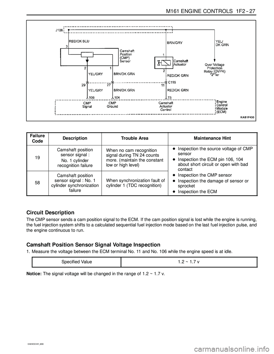
KAB1F430
Failure
CodeDescriptionTrouble AreaMaintenance Hint
19
Camshaft position
sensor signal :
No. 1 cylinder
recognition failureWhen no cam recognition
signal during TN 24 counts
more. (maintain the constant
low or high level)DInspection the source voltage of CMP
sensor
DInspection the ECM pin 106, 104
about short circuit or open with bad
contact
58
Camshaft position
sensor signal : No. 1
cylinder synchronization
failure
When synchronization fault of
cylinder 1 (TDC recognition)
contact
DInspection the CMP sensor
DInspection the damage of sensor or
sprocket
DInspection the ECM
Circuit Description
The CMP sensor sends a cam position signal to the ECM. If the cam position signal is lost while the engine is running,
the fuel injection system shifts to a calculated sequential fuel injection mode based on the last fuel injection pulse, and
the engine continuous to run.
Camshaft Position Sensor Signal Voltage Inspection
1. Measure the voltage between the ECM terminal No. 11 and No. 106 while the engine speed is at idle.
Specified Value
1.2~1.7v
Notice:The signal voltagewill be changed in the range of 1.2 ~ 1.7 v.
Page 448 of 2053

1F2 -- 28 M161 ENGINE CONTROLS
D AEW OO M Y_2000
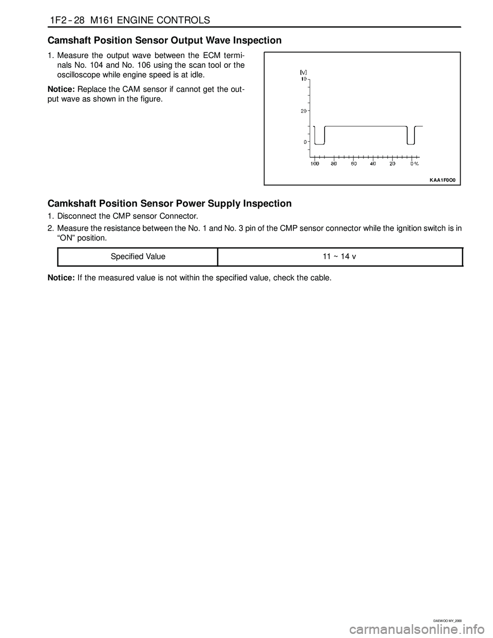
Camshaft Position Sensor Output Wave Inspection
1. Measure the output wave between the ECM termi-
nals No. 104 and No. 106 using the scan tool or the
oscilloscope whileengine speed is at idle.
Notice:Replace the CAM sensor if cannot get the out-
put wave as shown in the figure.
KAA1F0O0
Camkshaft Position Sensor Power Supply Inspection
1. Disconnect the CMP sensor Connector.
2. Measure the resistance between the No. 1 and No. 3 pin of the CMP sensor connector while the ignition switch is in
“ON” position.
Specified Value
11 ~ 14 v
Notice:If the measured value is not within the specified value, check the cable.
Page 459 of 2053

M161 ENGINE CONTROLS 1F2 -- 41
D AEW OO M Y_2000
Battery Voltage Correction Mode
When battery voltage is low, the ECM can compensate for a weak spark delivered by the ignition module by using the
following methods:
DIncreasing the fuel injector pulse width.
DIncreasing the idle speed rpm.
DIncreasing the ignition dwell time.
Fuel Cut- Off Mode
No fuel is delivered by the fuel injectors when the ignition is off. This prevents dieseling or engine run -- on. Also, the fuel
is not delivered if there are no reference pulses received from the CKP sensor. This prevents flooding.
Page 467 of 2053

M161 ENGINE CONTROLS 1F2 -- 49
D AEW OO M Y_2000
Injector Pulse Width Inspection
1. Turn the ignition switch OFF.
2. Install the scan tool.
3. Turn the ignition switch ON.
4. Monitor the “INJECTION TIME” with a scan tool.
Cranking
8.0 ms
Engine Idle3~5ms
Wide Open Throttle (WOT)14 ms
Page 473 of 2053

M161 ENGINE CONTROLS 1F2 -- 55
D AEW OO M Y_2000
The pressure difference between the fuel pressure and
the intake manifold is about 3.8 bars during the full load.
YAA1F500
1. Fuel Pressure Regulator
2. Intake Manifold
3. Fuel Return (to fuel tank)
4. Fuel Supply (from fuel pump)
5. Fuel Pressure (approx. 3.8 bars)
6. Intake Manifold Negative Pressure (0 bar)
The spring chamber (9) is connected to the intake man-
ifold with the vacuum hose at the intake pipe connection
(7). The negative pressure generated in the intake man-
ifold activates the diaphragm, and thus the fuel pressure
gets reduced to the rate of the operating extent of the
diaphragm by the intake manifold’s negative pressure.
YAA1F510
Consequently, the fuel pressure in the fuel distributor
changes by the intake manifold’s negative pressure, and
the injector ’s fuel pressure gets reduced independentlyto the throttle valve’s position. Thus, the fuel injection
volume can only be determined according to the injec-
tor’s injecting duration.
The pressure difference between the fuel pressure and
the intake manifold is approx. 3.2 bars during idling.
YAA1F520
1. Fuel Pressure Regulator
2. Intake Manifold
3. Fuel Return (to fuel tank)
4. Fuel Supply (from fuel pump)
7. Fuel Pressure (approx. 3.2 bars)
8. Intake Manifold Negative Pressure (0.6 bars)
YAA1F530
A. Fuel pressure
B. Intake Manifold Negative Pressure
LL. Idling
TL. Partial load
VL. Full load