SSANGYONG KORANDO 1997 Service Service Manual
KORANDO 1997
SSANGYONG
SSANGYONG
https://www.carmanualsonline.info/img/67/57502/w960_57502-0.png
SSANGYONG KORANDO 1997 Service Service Manual
Page 553 of 2053
OM600 ENGINE MECHANICAL 1B3 -- 3
D AEW OO M Y_2000
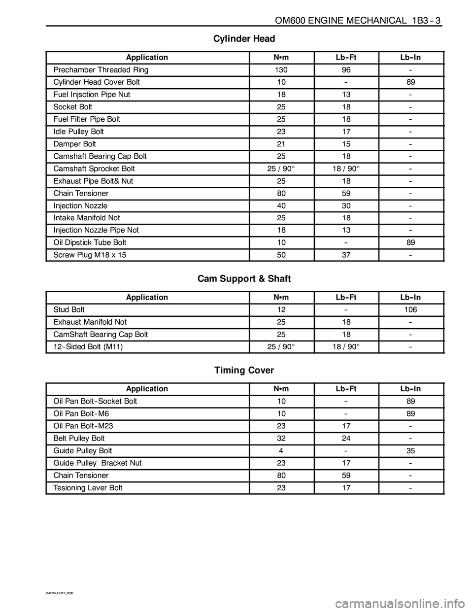
Cylinder Head
ApplicationNSmLb-- FtLb-- In
Prechamber Threaded Ring13096--
Cylinder Head Cover Bolt10--89
Fuel Injsction Pipe Nut1813--
Socket Bolt2518--
Fuel Filter Pipe Bolt2518--
Idle Pulley Bolt2317--
Damper Bolt2115--
Camshaft Bearing Cap Bolt2518--
Camshaft Sprocket Bolt25 / 90_18 / 90_--
Exhaust Pipe Bolt& Nut2518--
Chain Tensioner8059--
Injection Nozzle4030--
Intake Manifold Not2518--
Injection Nozzle Pipe Not1813--
Oil Dipstick Tube Bolt10--89
Screw Plug M18 x 155037--
Cam Support & Shaft
ApplicationNSmLb-- FtLb-- In
Stud Bolt12--106
Exhaust Manifold Not2518--
CamShaft Bearing Cap Bolt2518--
12-- Sided Bolt (M11)25 / 90_18 / 90_--
Timing Cover
ApplicationNSmLb-- FtLb-- In
Oil Pan Bolt -- Socket Bolt10--89
Oil Pan Bolt--M610--89
Oil Pan Bolt--M232317--
Belt Pulley Bolt3224--
Guide Pulley Bolt4--35
Guide Pulley Bracket Nut2317--
Chain Tensioner8059--
Tesioning Lever Bolt2317--
Page 565 of 2053
1B3 -- 16 OM600 ENGINE MECHANICAL
D AEW OO M Y_2000
16. Remove the power steering pump lines.
Notice
Completely drain the fluid.
17. Disconnect the fuel feed line with prefilter from the
feed pump on injection pump.
18. Vehicle with automatic transmission.
Remove the hydraulic lines (19, 20) from oil cooler
(2).
19. Disconnect the engine harness.
20. Disconnect the preheating time relay cable.
Page 566 of 2053
OM600 ENGINE MECHANICAL 1B3 -- 17
D AEW OO M Y_2000
21. Remove the fuel lines from the fuel filter and cover
the filter with plug.
22. Disconnect the brake booster hose from vacuum
pump.
23. Disconnect the other vacuum lines.
24. Disconnect the ground cable.
25. Disconnect the generator wires.
26. Disconnect the starter motor wires and remove the
starter motor.
Page 586 of 2053

OM600 ENGINE MECHANICAL 1B3 -- 37
D AEW OO M Y_2000
CYLINDER HEAD
1 Fuel Injection Pipe 18N∙m (13 lb-ft) ..........
2 Cylinder Head
3 Gasket Replace..........................
4 Bolt 25N∙m (18 lb-ft) ......................
5 Washer
6 Clamp
7 Heater Feed Pipe
8Bolt
9 Washer
10 Bolt
11 Nozzle Washer Replace...................
12 Fuel Injection Nozzle 35 -- 40 N∙m(26--30 lb-ft)
13 Hexagon Socket Bolt 25 N∙m (18 lb-ft) ......
14 Washer
15 Bolt 25 N∙m (18 lb-ft) .....................
16 Cylinder Head Bolt See Table..............
17 Cylinder Head Cover
18 Bolt 10 N∙m (89 lb-in) .....................
19 Gasket
20 Camshaft21 Camshaft Drive Sprocket Replace...........
22 Washer
23 Bolt(12-- Sided) 25N∙m (18 lb-ft) + 90_ .......
24 Sliding Rail
25 Sliding Rail Pin
26 Sliding Rail Pin
27 Chain Tensioner 80 N∙m (59 lb-ft) ...........
28 Gasket Replace..........................
29 Cooling Fan Check.......................
30 Hexagon Socket Bolt 45 N∙m (33 lb-ft) ......
31 Tensioning Lever
32 Bolt 25 N∙m (18 lb-ft) .....................
33 Bolt
34 Nut 23 N∙m (17 lb-ft) ......................
35 Fuel Filter
36 Turbo Charger
37 Intake Duct
38 Gasket Replace..........................
39 Intake Manifold
Page 593 of 2053
1B3 -- 44 OM600 ENGINE MECHANICAL
D AEW OO M Y_2000
22. Remove the cable channel.
23 .Disconnect the cables from the glow plug sensor
and coolant temperature sensor.
24. Remove the heater pipe bracket from the oil filter.
25. Pry off the clamp and push the heater feed pipe for-
ward and then pull out the pipe.
Page 594 of 2053
OM600 ENGINE MECHANICAL 1B3 -- 45
D AEW OO M Y_2000
26. Disconnect the fuel lines from the fuel filter.
27. Disconnect the fuel lines from the injection pump.
28. Remove the fuel filter(35).
29. Remove the fuel injection nozzle(12) and nozzle
washer(11).
Socket Wrench Insert 001 589 65 09 00
Page 603 of 2053
1B3 -- 54 OM600 ENGINE MECHANICAL
D AEW OO M Y_2000
8. Connect the vacuum lines to the vacuum pump.
9. Install the fuel filter and connect the pipe.
Tightening Torque25 N∙m (18 lb-ft)
Notice
Be careful not to be confused the connections and
hoses.
10. Connect the fuel pipe to the injection pump.
11. Install the sliding rail(24) and insert the sliding rail
pins(25, 26).
Notice
Apply sealing compound on the each collar of the
sliding rail pins.
Sliding Hammer 116 589 20 33 00
Threaded Pin 116 589 02 34 00
Page 610 of 2053
OM600 ENGINE MECHANICAL 1B3 -- 61
D AEW OO M Y_2000
38. Replace the O -- ring of heater feed pipe and install it
to the cylinder head.
Notice
For installation, clean the hole.
39. Install the bracket of heater feed pipe to the oil filter.
40. Install the fuel pipe and the accelerator control link-
age.
41. Connect the fuel lines to the injection nozzles and to
the injection pump.
Tightening Torque18 N∙m (13 lb-ft)
Box Wrench Insert 000 589 77 03 00
Page 612 of 2053

OM600 ENGINE MECHANICAL 1B3 -- 63
D AEW OO M Y_2000
TIMING CASE COVER
Preceding Work : Removal of the cooling fan
Rmoval of the V-- belt tensioning device
Removal of the vibration damper and hub
Removal of the generator
1 Bolt 10N∙m (89 lb-in) .....................
2 Cylinder Head Cover
3 Gasket Replace..........................
4 Socket Bolt 25N∙m (18 lb-ft) ................
5 Fuel Filter
6 Square Nut
7OilPan
8 Socket Bolt 10N∙m (89 lb-in) ...............
9 Bolt M6 : 10N∙m (89 lb-in) ................
M8 : 23N∙m (17 lb-ft)
10 Power Steering Pump
11 Bolt
12 Belt Pulley13 Bolt 32N∙m (24 lb-ft) ......................
14 Timing Case Cover
15 Bolt 23N∙m (17 lb-ft) ......................
16 Generator Bracket
17 Bolt 45N∙m (33 lb-ft) ......................
18 Bolt 25N∙m (18 lb-ft) ......................
19 Bolt 10N∙m(89lb-in) .....................
20 Closing Cover
21 Socket Bolt 23N∙m (17 lb-ft) ................
22 Guide Pulley
23 Bolt 9N∙m(80lb-in) .......................
24 Guide Pulley Bracket
25 Nut 23N∙m (17 lb-ft) .......................
Page 614 of 2053
OM600 ENGINE MECHANICAL 1B3 -- 65
D AEW OO M Y_2000
9. Disconnect the pipes of power steering pump and
remove the belt pulley.
Notice
Be careful not to lose the key.
10. Remove the nut and pull out the bolt and then re-
move the power steering pump.
11. Remove the generator bracket (16).
12. Remove the fuel filter.


