transmission SSANGYONG KORANDO 2012 Owner's Manual
[x] Cancel search | Manufacturer: SSANGYONG, Model Year: 2012, Model line: KORANDO, Model: SSANGYONG KORANDO 2012Pages: 1082, PDF Size: 96.1 MB
Page 842 of 1082
02-8
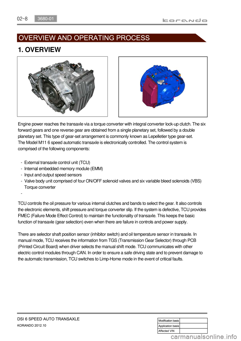
1. OVERVIEW
Engine power reaches the transaxle via a torque converter with integral converter lock-up clutch. The six
forward gears and one reverse gear are obtained from a single planetary set, followed by a double
planetary set. This type of gear-set arrangement is commonly known as Lepelletier type gear-set.
The Model M11 6 speed automatic transaxle is electronically controlled. The control system is
comprised of the following components:
External transaxle control unit (TCU)
Internal embedded memory module (EMM)
Input and output speed sensors
Valve body unit comprised of four ON/OFF solenoid valves and six variable bleed solenoids (VBS)
Torque converter -
-
-
-
-
TCU controls the oil pressure for various internal clutches and bands to select the gear. It also controls
the electronic elements, shift pressure and torque converter slip. If the system is defective, TCU provides
FMEC (Failure Mode Effect Control) to maintain the functionality of transaxle. This keeps the basic
function of transaxle (gear selection) even when there are failure in controls and power supply.
There are selector shaft position sensor (inhibitor switch) and oil temperature sensor in transaxle. In
manual mode, TCU receives the information from TGS (Transmission Gear Selector) through PCB
(Printed Circuit Board) when driver selects the manual shift mode. TCU communicates with other
electric control modules through CAN. In order to ensure a safe driving state and to prevent damage to
the automatic transmission, TCU switches to Limp-Home mode in the event of critical faults.
Page 848 of 1082
02-14
5. TRANSAXLE ELECTRONIC CONTROL SYSTEM
1) General Information
The transmission control unit (TCU) and its input/output network control the following transmission
operations:
Shift timing
Line pressure
Clutch pressure (shift feel)
Torque converter clutch -
-
-
-
also uses these signals when determining transaxle operating strategy. Using all of these input signals,
the TCU can determine when the time and conditions are right for a shift, or when to apply or release the
torque converter clutch. It will also determine the pressure needed to optimise shift feel. To accomplish
this, the TCU operates six variable bleed control solenoids and four on/off solenoids to control transaxle
operation.
2) TCU (Transmission Control Unit)
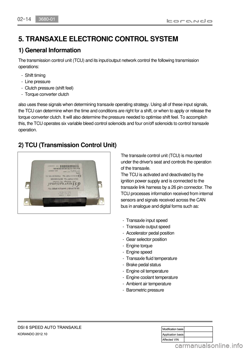
The transaxle control unit (TCU) is mounted
under the driver's seat and controls the operation
of the transaxle.
The TCU is activated and deactivated by the
ignition power supply and is connected to the
transaxle link harness by a 26 pin connector. The
TCU processes information received from internal
sensors and signals received across the CAN
bus in analogue and digital forms such as:
Transaxle input speed
Transaxle output speed
Accelerator pedal position
Gear selector position
Engine torque
Engine speed
Transaxle fluid temperature
Brake pedal status
Engine oil temperature
Engine coolant temperature
Ambient air temperature
Barometric pressure -
-
-
-
-
-
-
-
-
-
-
-
Page 850 of 1082
02-16
3) Shift Map Selection
The driver can manually select between normal (S) and winter modes (W) via the mode switch.
Depending on the transaxle temperature, uphill and downhill grades and altitude, shift maps will be
selected by the TCU to suit the driving conditions. The following maps are available.
Standard (Normal) Mode ▶
Normal Mode is selected when the lever is in the D position with the mode switch in the normal (S)
position and the transaxle is within normal temperature ranges. Shift schedule points are optimised for
fuel efficiency and general driving conditions.
Uphill and Downhill Mode ▶
In this mode, depending on the load of the vehicle, adaptive shift maps are selected to progressively
adjust the shift points and torque converter lock points.
Altitude Mode ▶
Shift points are automatically adjusted at higher altitudes to compensate for changes in engine torque
where the torque produced by the engine is greatly reduced by the effects of reduced barometric
pressure and temperature.
Winter (W) Mode ▶
When winter mode is selected, starting in second gear is facilitated and the WINTER mode indicator
light is switched ON. To prevent wheel spin on slippery surfaces, the transmission will not allow first gear
unless manually overridden.
Warm up Schedule ▶
<007c009a008c008b0047009b00a000970090008a00880093009300a00047009e008f008c00950047009b009900880095009a0088009f0093008c0047008d0093009c0090008b0047009b008c00940097008c00990088009b009c0099008c00470090009a00
470089008c00930096009e00470059005700b6006a0055>
The torque converter will not lock-up below 20°C to assist in transaxle warm-up.
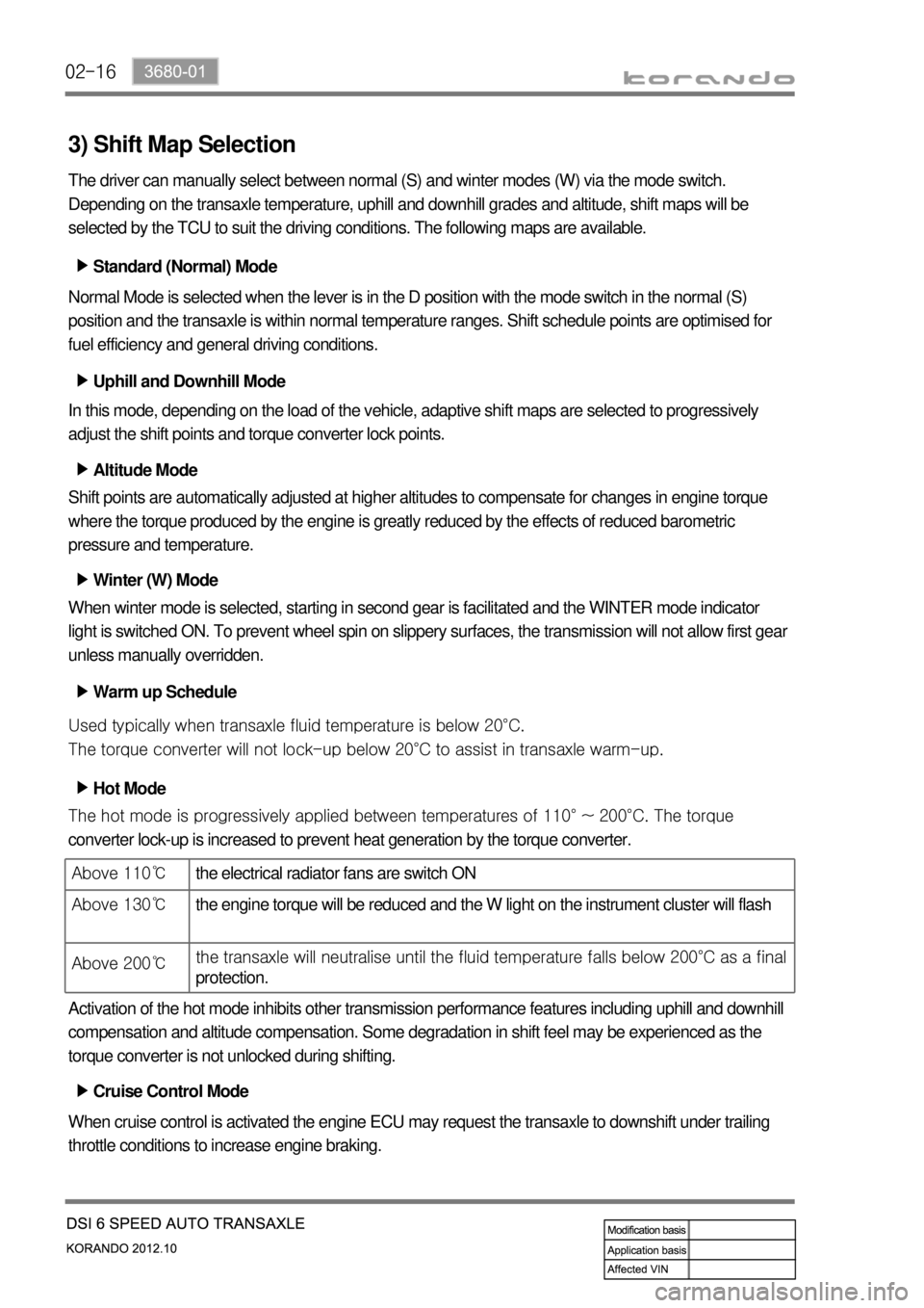
Hot Mode ▶
<007b008f008c0047008f0096009b004700940096008b008c00470090009a0047009700990096008e0099008c009a009a0090009d008c009300a0004700880097009700930090008c008b00470089008c009b009e008c008c00950047009b008c0094009700
8c00990088009b009c0099008c009a00470096008d00470058>10° ~ 200°C. The torque
converter lock-up is increased to prevent heat generation by the torque converter.
Activation of the hot mode inhibits other transmission performance features including uphill and downhill
compensation and altitude compensation. Some degradation in shift feel may be experienced as the
torque converter is not unlocked during shifting.
Cruise Control Mode ▶
When cruise control is activated the engine ECU may request the transaxle to downshift under trailing
throttle conditions to increase engine braking.
Above 110℃the electrical radiator fans are switch ON
Above 130℃the engine torque will be reduced and the W light on the instrument cluster will flash
Above 200℃the transaxle will neutralise until the fluid tem
perature falls below 200°C as a final
protection.
Page 863 of 1082
03-33660-01
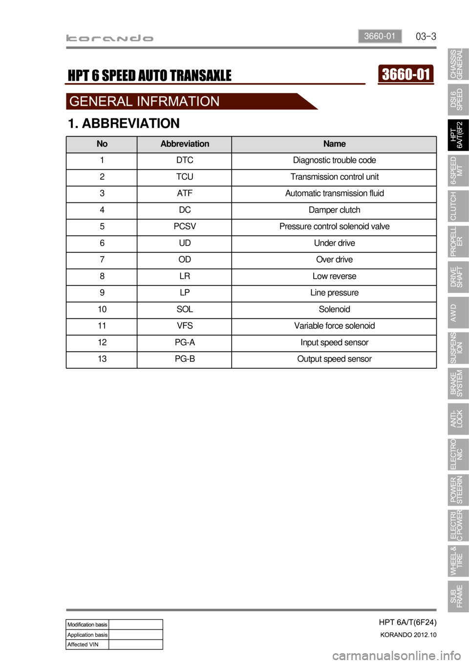
1. ABBREVIATION
No Abbreviation Name
1 DTC Diagnostic trouble code
2 TCU Transmission control unit
3 ATF Automatic transmission fluid
4 DC Damper clutch
5 PCSV Pressure control solenoid valve
6 UD Under drive
7OD Over drive
8 LR Low reverse
9 LP Line pressure
10 SOL Solenoid
11 VFS Variable force solenoid
12 PG-A Input speed sensor
13 PG-B Output speed sensor
Page 871 of 1082
03-113660-01
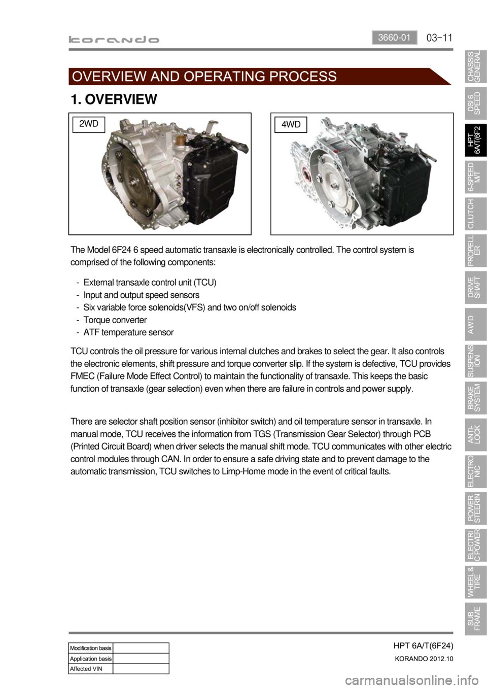
1. OVERVIEW
2WD4WD
The Model 6F24 6 speed automatic transaxle is electronically controlled. The control system is
comprised of the following components:
External transaxle control unit (TCU)
Input and output speed sensors
Six variable force solenoids(VFS) and two on/off solenoids
Torque converter
ATF temperature sensor -
-
-
-
-
TCU controls the oil pressure for various internal clutches and brakes to select the gear. It also controls
the electronic elements, shift pressure and torque converter slip. If the system is defective, TCU provides
FMEC (Failure Mode Effect Control) to maintain the functionality of transaxle. This keeps the basic
function of transaxle (gear selection) even when there are failure in controls and power supply.
There are selector shaft position sensor (inhibitor switch) and oil temperature sensor in transaxle. In
manual mode, TCU receives the information from TGS (Transmission Gear Selector) through PCB
(Printed Circuit Board) when driver selects the manual shift mode. TCU communicates with other electric
control modules through CAN. In order to ensure a safe driving state and to prevent damage to the
automatic transmission, TCU switches to Limp-Home mode in the event of critical faults.
Page 877 of 1082
03-173660-01
5. TRANSAXLE ELECTRONIC CONTROL SYSTEM
1) General Information
The transmission control unit (TCU) and its input/output network control the following transmission
operations:
Shift timing
Line pressure
Clutch pressure (shift feel)
Torque converter clutch -
-
-
-
also uses these signals when determining transaxle operating strategy. Using all of these input signals,
the TCU can determine when the time and conditions are right for a shift, or when to apply or release the
torque converter clutch. It will also determine the pressure needed to optimise shift feel.
2) TCU (Transmission Control Unit)
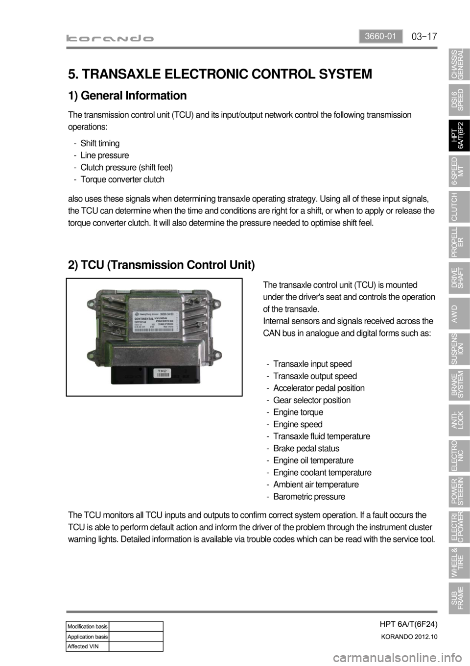
The transaxle control unit (TCU) is mounted
under the driver's seat and controls the operation
of the transaxle.
Internal sensors and signals received across the
CAN bus in analogue and digital forms such as:
Transaxle input speed
Transaxle output speed
Accelerator pedal position
Gear selector position
Engine torque
Engine speed
Transaxle fluid temperature
Brake pedal status
Engine oil temperature
Engine coolant temperature
Ambient air temperature
Barometric pressure -
-
-
-
-
-
-
-
-
-
-
-
The TCU monitors all TCU inputs and outputs to confirm correct system operation. If a fault occurs the
TCU is able to perform default action and inform the driver of the problem through the instrument cluster
warning lights. Detailed information is available via trouble codes which can be read with the service tool.
Page 888 of 1082
03-33190-01
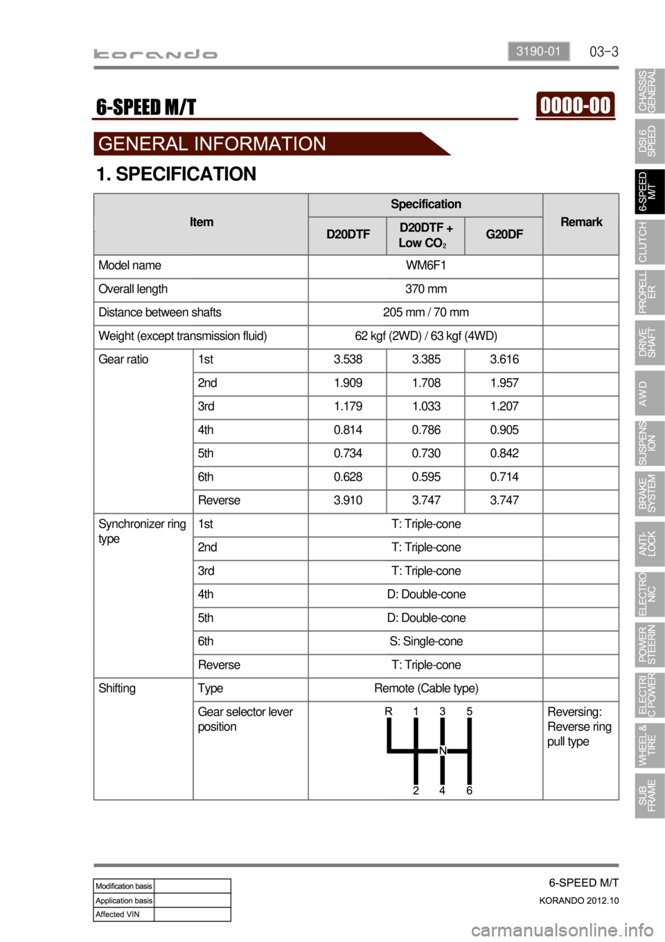
1. SPECIFICATION
DG20DD
Model name WM6F1
Overall length 370 mm
Distance between shafts 205 mm / 70 mm
Weight (except transmission fluid) 62 kgf (2WD) / 63 kgf (4WD)
Gear ratio 1st 3.538 3.385 3.616
2nd 1.909 1.708 1.957
3rd 1.179 1.033 1.207
4th 0.814 0.786 0.905
5th 0.734 0.730 0.842
6th 0.628 0.595 0.714
Reverse 3.910 3.747 3.747
Synchronizer ring
type1st T: Triple-cone
2nd T: Triple-cone
3rd T: Triple-cone
4th D: Double-cone
5th D: Double-cone
6th S: Single-cone
Reverse T: Triple-cone
Shifting Type Remote (Cable type)
Gear selector lever
positionReversing:
Reverse ring
pull type
ItemSpecification
Remark
D20DTFD20DTF +
Low CO₂G20DF
Page 889 of 1082
03-4
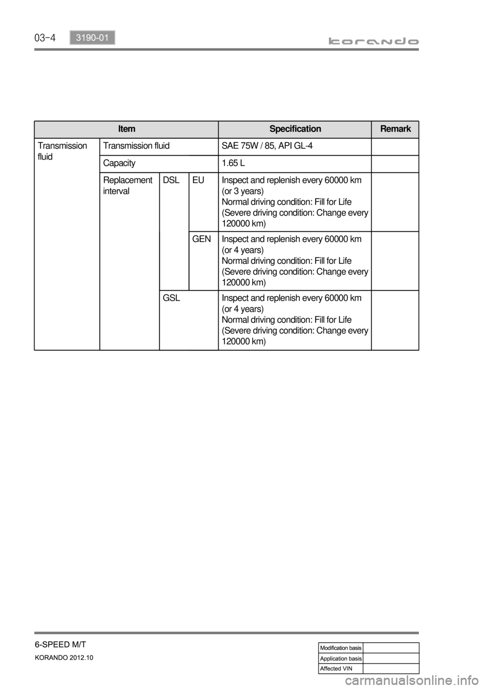
Item Specification Remark
Transmission
fluidTransmission fluid SAE 75W / 85, API GL-4
Capacity 1.65 L
Replacement interval EU Inspect and replenish every 60000 km
(or 3 years)
Normal driving condition: Fill for Life
(Severe driving condition: Change every
120000 km)
GEN Inspect and replenish every 60000 km
(or 4 years)
Normal driving condition: Fill for Life
(Severe driving condition: Change every
120000 km)
Replacement
interval DSL EU
GEN
GSL Inspect and replenish every 60000 km
(or 4 years)
Normal driving condition: Fill for Life
(Severe driving condition: Change every
120000 km)
Page 890 of 1082

03-53190-01
2. TIGHTENING TORQUE
Part name Tightening torque Remark
1. Drive gear mounting bolt of differential carrier 166.6 to 176.4 Nm 10 EA
2. Reverse shaft mounting bolt 74.5 to 89.2 Nm
3. Transmission case mounting bolt 19.6 to 26.5 Nm 22 EA
4. Concentric slave cylinder mounting bolt 11.8 to 14.7 Nm 3 EA
5. Backup lamp switch 29.4 to 34.3 Nm
6. Neutral switch 29.4 to 34.3 Nm
7. Oil filler plug 58.8 to 78.4 Nm
8. Oil drain plug 58.8 to 78.4 Nm
9. Oil plug 58.8 to 78.4 Nm
10. Shift lever mounting nut 42.2 to 53.9 Nm
11. Selector lever mounting nut 42.2 to 53.9 Nm
12. Control shaft assembly mounting bolt 9.8 to 11.8 Nm 7 EA
13. Guide bolt 42.2 to 53.9 Nm
Page 892 of 1082

03-73190-01
Front view Rear view
1. OVERVIEW
This vehicle is equipped with WM6F1 M/T (Manual Transmission). This transmission is integrated with an
axle and designed to maximize the driving performance by optimizing the gear ratio according to the
engine torque.
WM6F1 M/T assembly