SSANGYONG KORANDO 2012 Owner's Manual
KORANDO 2012
SSANGYONG
SSANGYONG
https://www.carmanualsonline.info/img/67/57504/w960_57504-0.png
SSANGYONG KORANDO 2012 Owner's Manual
Page 521 of 1082
14-150000-00
8. DTC SETTING CONDITIONS
Charge warning lamp ON condition ▶
Turn the ignition ON (Engine stopped)
Open or short circuit of L terminal wiring, open or short internal circuit of alternator (fixed control of
13.8V)
Open or short circuit of F terminal wiring, no feedback output signal 1.
2.
3.
Page 534 of 1082
01-10
4. SCHEMATIC DIAGRAM FOR WIRING AND ELECTRICAL
DEVICES
1) Wiring Harness Arrangement
Page 539 of 1082
01-150000-00
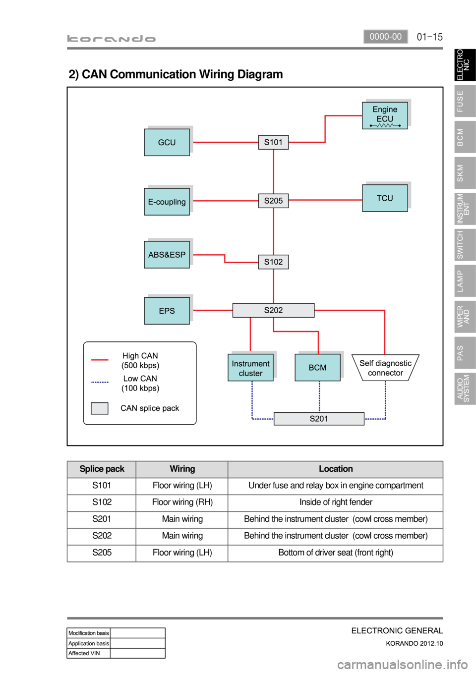
2) CAN Communication Wiring Diagram
Splice pack Wiring Location
S101 Floor wiring (LH) Under fuse and relay box in engine compartment
S102 Floor wiring (RH) Inside of right fender
S201 Main wiring Behind the instrument cluster (cowl cross member)
S202 Main wiring Behind the instrument cluster (cowl cross member)
S205 Floor wiring (LH) Bottom of driver seat (front right)
Page 542 of 1082
02-4
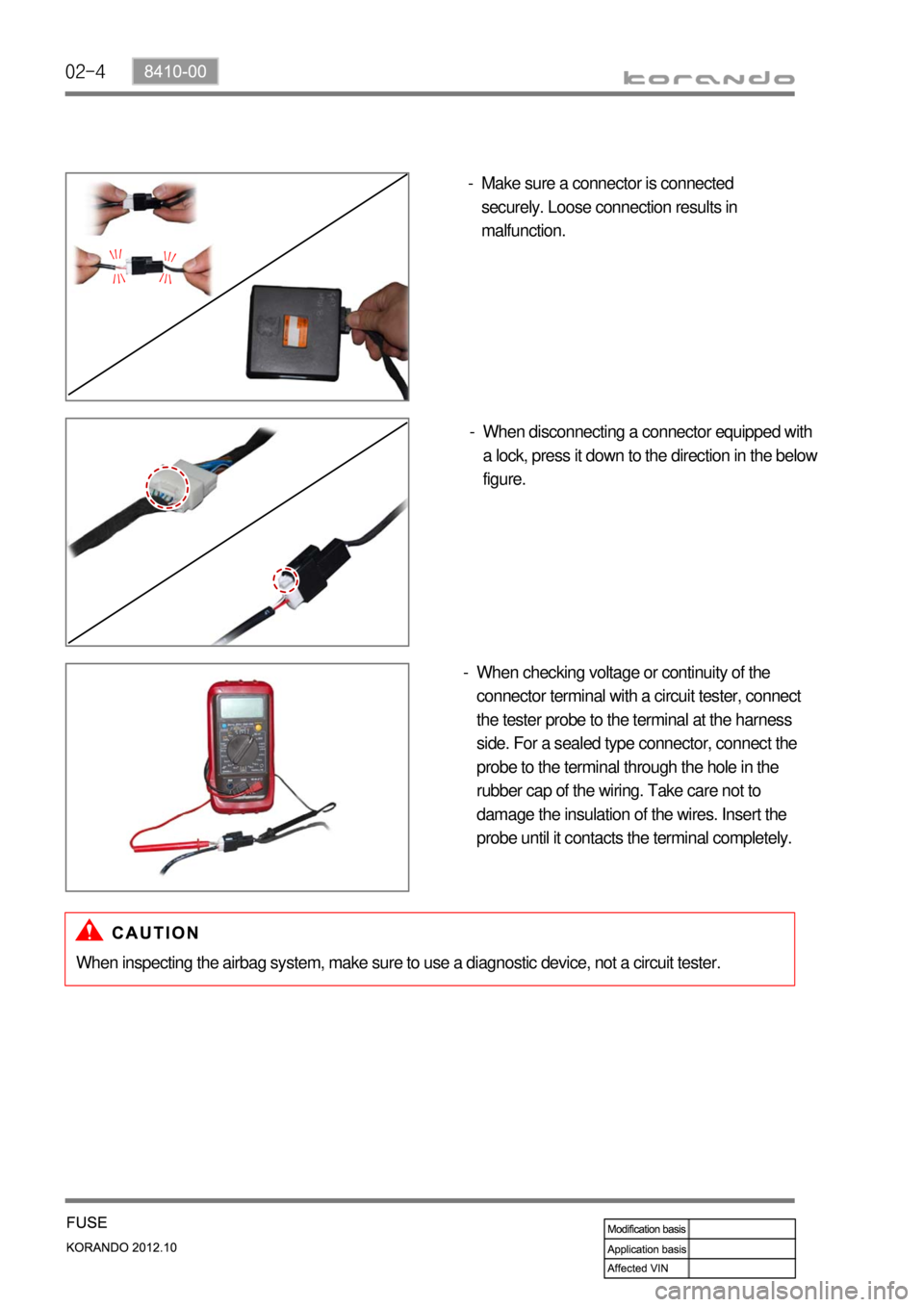
Make sure a connector is connected
securely. Loose connection results in
malfunction. -
When disconnecting a connector equipped with
a lock, press it down to the direction in the below
figure. -
When checking voltage or continuity of the
connector terminal with a circuit tester, connect
the tester probe to the terminal at the harness
side. For a sealed type connector, connect the
probe to the terminal through the hole in the
rubber cap of the wiring. Take care not to
damage the insulation of the wires. Insert the
probe until it contacts the terminal completely. -
When inspecting the airbag system, make sure to use a diagnostic device, not a circuit tester.
Page 543 of 1082
02-58410-00
2. CHECKING CABLES AND WIRES
Check for loose connection or rust.
Check terminals and wires for corrosion due to electrolyte leakage.
Check terminals and wires for open circuit.
Check the wire insulation and coat for damage, cracks or deterioration.
Check if the conductive parts of the terminals do not contact with vehicle body or other metal parts.
Check that the grounding part has continuity with mounting bolts and vehicle body.
Check that wires are properly routed.
Make sure that wires are securely fixed to avoid contact with sharp body parts and high-temperature
parts, such as the exhaust manifold and exhaust pipes.
The rotating parts, such as fan pulley and fan belt, perturbative parts and wiring should be secured
tightly at regular intervals.
Secure the wiring between the fixed parts, such as the vehicle body, and vibrating parts, such as the
engine, after slackening it slightly to prevent it from being damaged. -
-
-
-
-
-
-
-
-
-
Page 554 of 1082
02-16
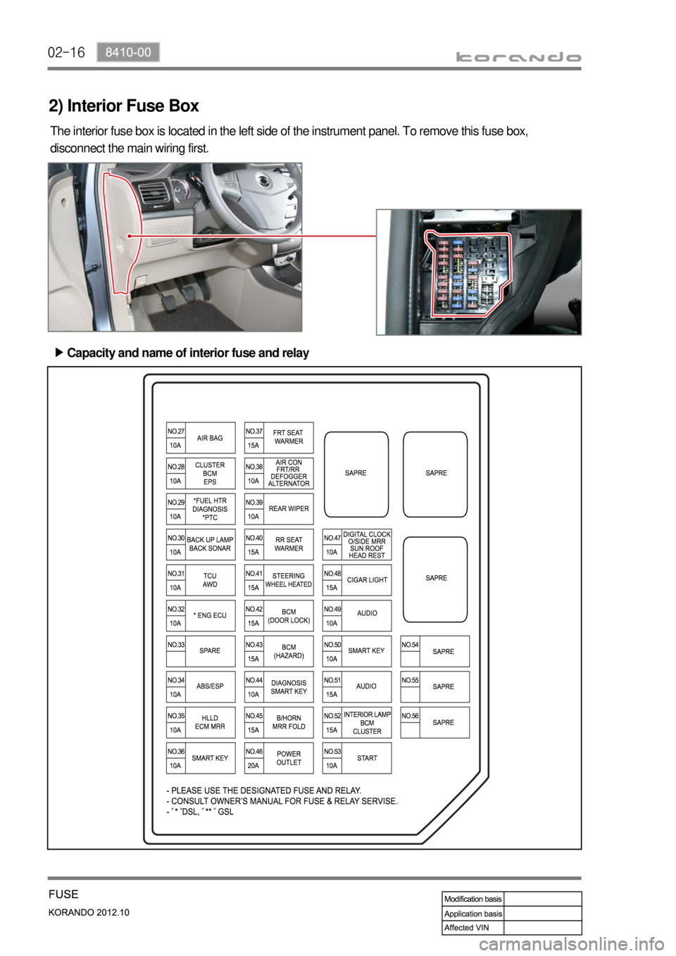
2) Interior Fuse Box
The interior fuse box is located in the left side of the instrument panel. To remove this fuse box,
disconnect the main wiring first.
Capacity and name of interior fuse and relay ▶
Page 742 of 1082
06-318510-00
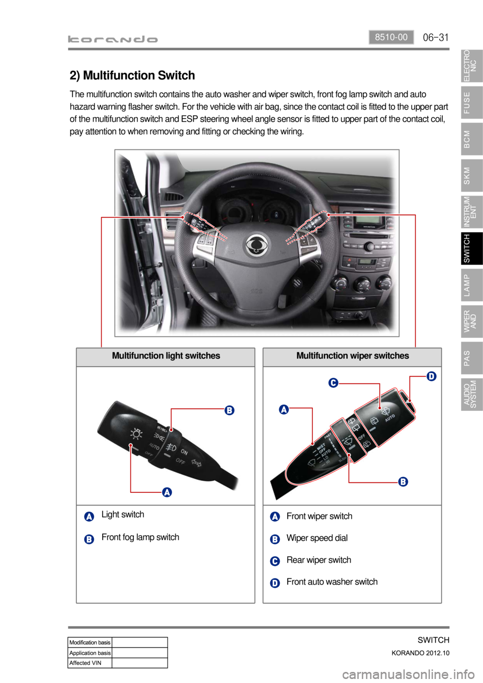
Multifunction wiper switches
2) Multifunction Switch
Multifunction light switches
Light switch
Front wiper switch
Wiper speed dial
Rear wiper switch Front fog lamp switch
Front auto washer switch The multifunction switch contains the auto washer and wiper switch, front fog lamp switch and auto
hazard warning flasher switch. For the vehicle with air bag, since the contact coil is fitted to the upper part
of the multifunction switch and ESP steering wheel angle sensor is fitted to upper part of the contact coil,
pay attention to when removing and fitting or checking the wiring.
Page 893 of 1082
03-8
1) Characteristics of WM6F1 M/T
Both Forward and Reverse gears use the helical gear and are made of high-strength material.
Drives the clutch with a concentric slave cylinder mounting bolt.
Shifting the transmission gears is performed through the remote control cable.
A pull type clutch is used for Reverse gear shifting.
Features triple/double/single synchronization. -
-
-
-
-
Clutch housing
Transmission case
Input shaft
Concentric slave cylinder
Shift lever
Selector lever
Wiring bracket
Neutral switch
Backup lamp switch
Reverse idle shaft mounting bolt 1.
2.
3.
4.
5.
6.
7.
8.
9.
10.Control guide bolt
Oil filler plug (for servicing)
Oil drain plug
Oil filler plug (for manufacturing)
Air breather
Detent pin (for securing shift fork)
Oil seal (RH)
Oil seal (LH)
Control housing 11.
12.
13.
14.
15.
16.
17.
18.
19.
Page 1005 of 1082
01-4
2. MAJOR CHANGES
1) Heater & Evaporator Module (Wiring Specification)
The driving circuit for the manual A/C ambient temperature sensor is added, giving the change to the
heater and evaporator module.
Ambient temperature sensor signal wiring
added to vehicle wiring connecting
connector (2 circuits)
: manual A/CBlower max signal wiring added to
vehicle wiring connecting connector
(1 circuit)
: manual A/C & FATC
Manual A/C: Wiring pin added to controller assembly connector
FATC: Wiring pin added to existing connector of controller assembly
Page 1019 of 1082
02-38810-00
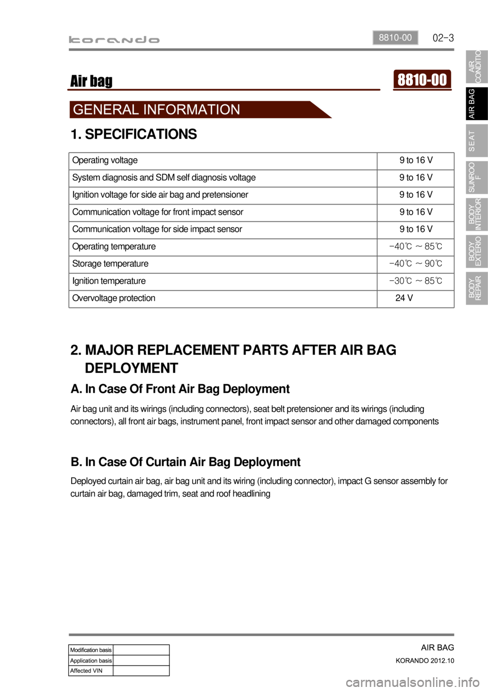
1. SPECIFICATIONS
Operating voltage 9 to 16 V
System diagnosis and SDM self diagnosis voltage 9 to 16 V
Ignition voltage for side air bag and pretensioner 9 to 16 V
Communication voltage for front impact sensor 9 to 16 V
Communication voltage for side impact sensor 9 to 16 V
Operating temperature -40℃ ~ 85℃
Storage temperature -40℃ ~ 90℃
Ignition temperature -30℃ ~ 85℃
Overvoltage protection 24 V
2. MAJOR REPLACEMENT PARTS AFTER AIR BAG
DEPLOYMENT
A. In Case Of Front Air Bag Deployment
Air bag unit and its wirings (including connectors), seat belt pretensioner and its wirings (including
connectors), all front air bags, instrument panel, front impact sensor and other damaged components
B. In Case Of Curtain Air Bag Deployment
Deployed curtain air bag, air bag unit and its wiring (including connector), impact G sensor assembly for
curtain air bag, damaged trim, seat and roof headlining


