cooling SSANGYONG NEW REXTON 2012 User Guide
[x] Cancel search | Manufacturer: SSANGYONG, Model Year: 2012, Model line: NEW REXTON, Model: SSANGYONG NEW REXTON 2012Pages: 600, PDF Size: 73.29 MB
Page 379 of 600

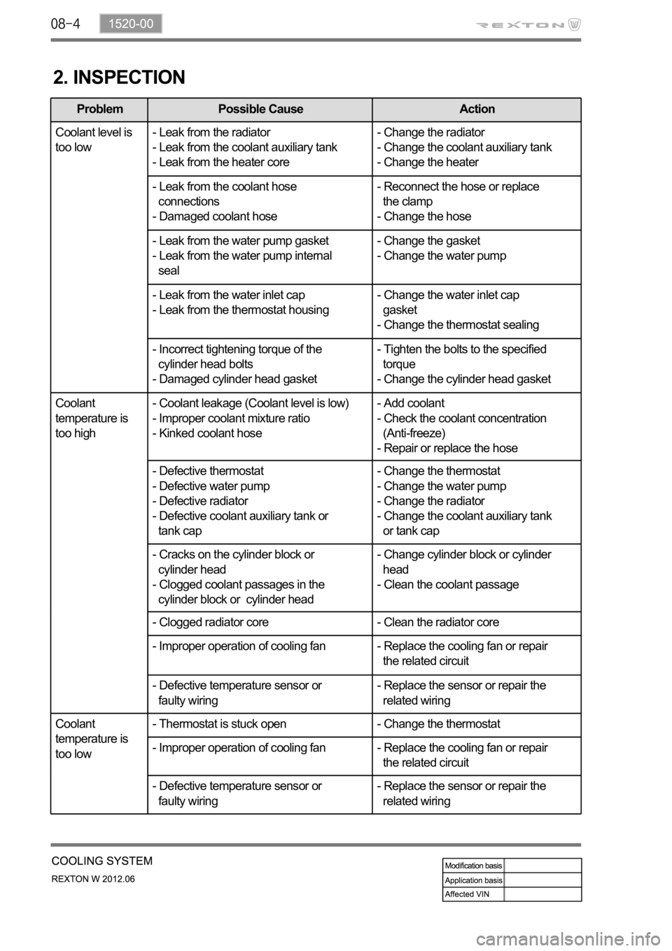
2. INSPECTION
Problem Possible Cause Action
Coolant level is
too low- Leak from the radiator
- Leak from the coolant auxiliary tank
- Leak from the heater core- Change the radiator
- Change the coolant auxiliary tank
- Change the heater
- Leak from the coolant hose
connections
- Damaged coolant hose- Reconnect the hose or replace
the clamp
- Change the hose
- Leak from the water pump gasket
- Leak from the water pump internal
seal- Change the gasket
- Change the water pump
- Leak from the water inlet cap
- Leak from the thermostat housing- Change the water inlet cap
gasket
- Change the thermostat sealing
- Incorrect tightening torque of the
cylinder head bolts
- Damaged cylinder head gasket- Tighten the bolts to the specified
torque
- Change the cylinder head gasket
Coolant
temperature is
too high- Coolant leakage (Coolant level is low)
- Improper coolant mixture ratio
- Kinked coolant hose- Add coolant
- Check the coolant concentration
(Anti-freeze)
- Repair or replace the hose
- Defective thermostat
- Defective water pump
- Defective radiator
- Defective coolant auxiliary tank or
tank cap- Change the thermostat
- Change the water pump
- Change the radiator
- Change the coolant auxiliary tank
or tank cap
- Cracks on the cylinder block or
cylinder head
- Clogged coolant passages in the
cylinder block or cylinder head- Change cylinder block or cylinder
head
- Clean the coolant passage
- Clogged radiator core - Clean the radiator core
- Improper operation of cooling fan - Replace the cooling fan or repair
the related circuit
- Defective temperature sensor or
faulty wiring- Replace the sensor or repair the
related wiring
Coolant
temperature is
too low- Thermostat is stuck open - Change the thermostat
- Improper operation of cooling fan - Replace the cooling fan or repair
the related circuit
- Defective temperature sensor or
faulty wiring- Replace the sensor or repair the
related wiring
Page 382 of 600

1520-00
3. CAUTIONS
If 100% of anti-freeze is added, the water pump vane can be damaged and thermal conductivity
can be decreased resulting in poor circulation in the cooling system which leads to overheated
engine.
Use of non-recommended coolant could cause damage to the cooling system and overheating of
the engine.
Opening the coolant reservoir cap while the engine is running or hot can cause burns by hot steam
or water.
To open the coolant reservoir cap, wrap the cap with a wet towel or thick cloth after the engine is
cooled down sufficiently.
If cool water is added to the heated engine, the engine or radiator can be deformed.
The anti-freeze in the coolant can damage the painted surface, so avoid the contact of the coolant
to the painted body.
The anti-freeze and water should be mixed in proper mixture ratio. Never add only water when
adding coolant.
If the anti-freeze content is too low, the coolant can be frozen while the engine can be overheated if
anti-freeze content is too high. -
-
-
-
-
-
-
-
Page 419 of 600

1793-00
1. SPECIFICATION
Item Specification
E-EGR valveMotorEGR response time 50 ms
Driven by DC motor
Valve EGR gas flow rate 120 kg/h
Cooling capacity 8.3 kW or more
Cooling fin type Wavy fin
Cooler type U-shaped
E-EGR bypass valve Solenoid valve Drivien byVacuum
(Solenoid valve)
E-EGR cooler
Position sensorSensing type Hole sensor
Supplied voltageMaximum signal
range5% ~ 95%
Maximum power
consumption
Page 446 of 600

(3) Components for ECU Output
CAN
E-EGR cooler
bypass valve
- Instrument cluster
- TCU
- Self diagnosis
PTC heaterCooling fan
E-EGR valve
Variable swirl
valveE-VGT actuatorIMV valve
A/C compressorInjectorThrottle position
sensor
- Glow plug unit
- ABS & ESP unit
- GCU
Page 476 of 600

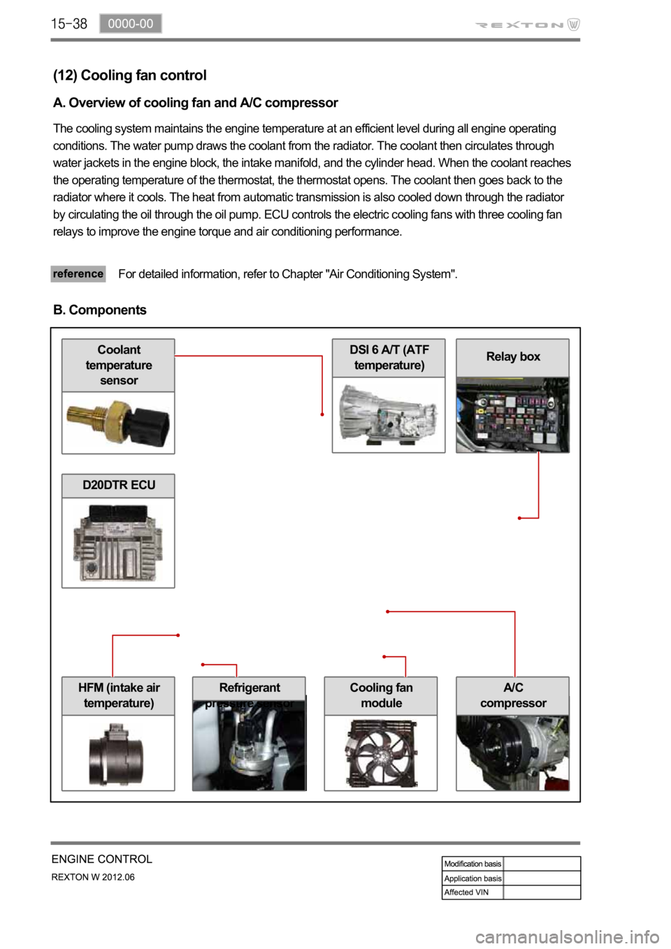
HFM (intake air
temperature)Cooling fan
module
DSI 6 A/T (ATF
temperature)Coolant
temperature
sensor
Refrigerant
pressure sensor
Relay box
(12) Cooling fan control
A. Overview of cooling fan and A/C compressor
The cooling system maintains the engine temperature at an efficient level during all engine operating
conditions. The water pump draws the coolant from the radiator. The coolant then circulates through
water jackets in the engine block, the intake manifold, and the cylinder head. When the coolant reaches
the operating temperature of the thermostat, the thermostat opens. The coolant then goes back to the
radiator where it cools. The heat from automatic transmission is also cooled down through the radiator
by circulating the oil through the oil pump. ECU controls the electric cooling fans with three cooling fan
relays to improve the engine torque and air conditioning performance.
For detailed information, refer to Chapter "Air Conditioning System".
B. Components
A/C
compressor
D20DTR ECU
Page 477 of 600

0000-00
C. Input/Output for cooling fan and A/C compressor
Page 478 of 600

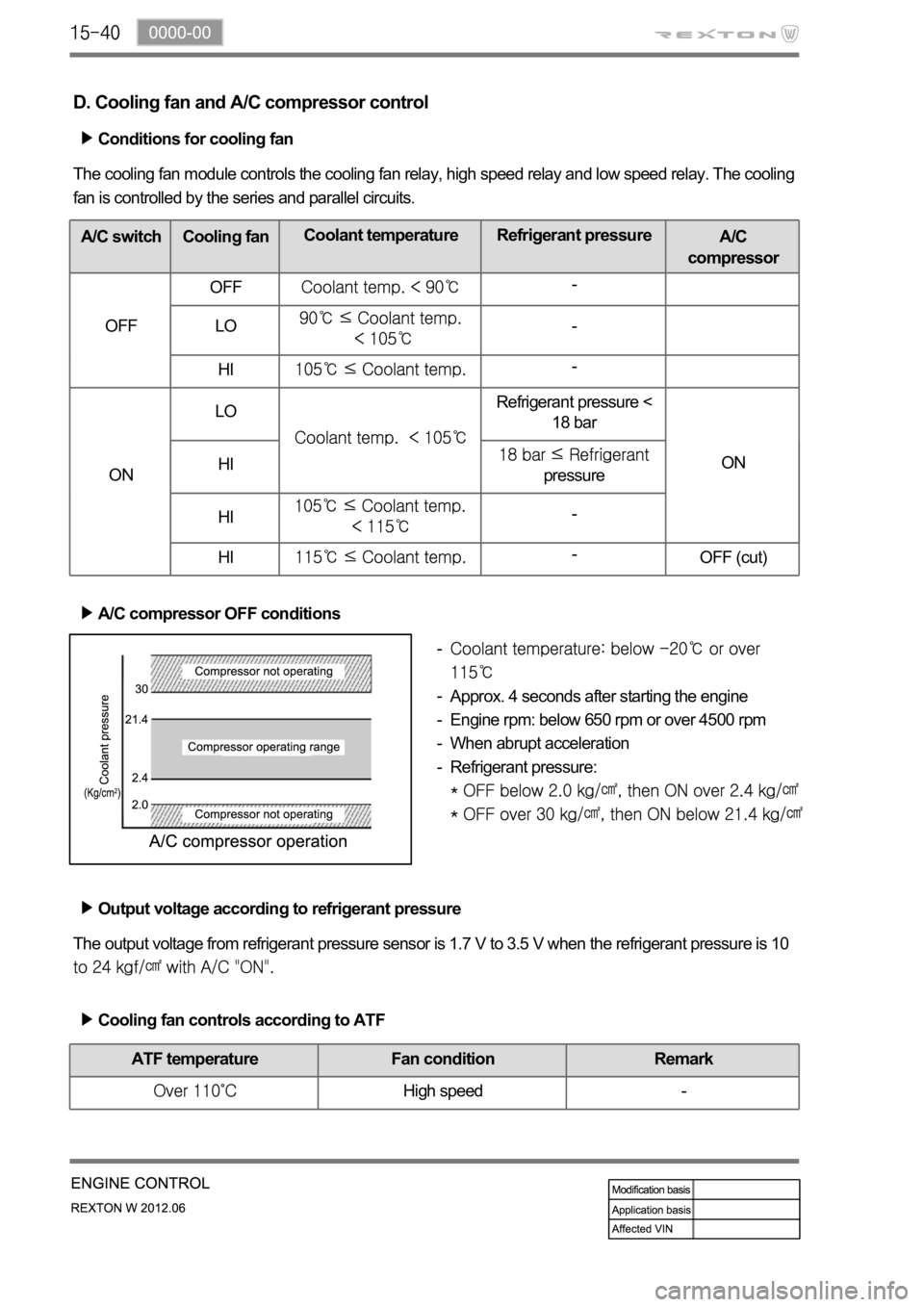
D. Cooling fan and A/C compressor control
Conditions for cooling fan
The cooling fan module controls the cooling fan relay, high speed relay and low speed relay. The cooling
fan is controlled by the series and parallel circuits.
A/C switch Cooling fanCoolant temperature Refrigerant pressure
A/C
compressor
OFF OFF
-
LO
-
HI
-
ONLO
Refrigerant pressure <
18 bar
ON
HI
pressure
HI
-
HI
-
OFF (cut)
A/C compressor OFF conditions
Approx. 4 seconds after starting the engine
Engine rpm: below 650 rpm or over 4500 rpm
When abrupt acceleration
Refrigerant pressure:
-
-
-
-
-
The output voltage from refrigerant pressure sensor is 1.7 V to 3.5 V when the refrigerant pressure is 10
Output voltage according to refrigerant pressure
Cooling fan controls according to ATF
ATF temperature Fan condition Remark
High speed -
Page 522 of 600

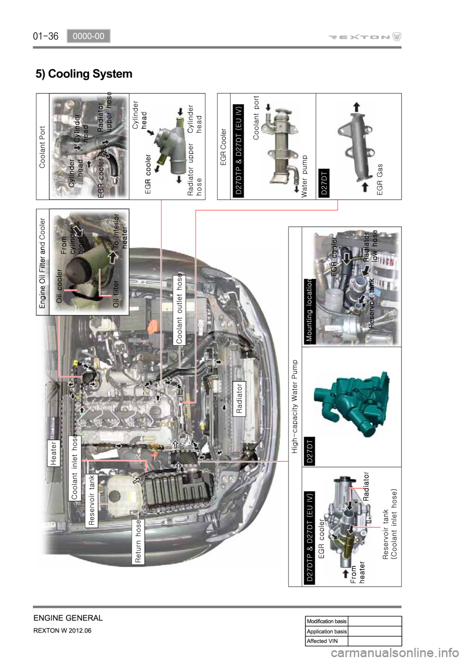
5) Cooling System
Page 541 of 600

1792-01
1. COMPONENTS
The components of the exhaust system for the D27DTP (POWER UP) engine have been changed
as follows:
1. E-EGR valve: Controlling the EGR valve electrically and sends the valve location signal to
ECU (vacuum modulator control has been deleted)
2. EGR cooler: Decreasing EGR gas (NOx) efficiently by cooling the EGR gas and let it flow to
the intake pipe
3. VGT turbocharger: Increase in capacity and performance compared to D27DTP & D20DT
engine
The EGR system has been changed to control NOx more efficiently and the VGT turbo charger
has been changed to increase the engine power. For more details, refer to the next description.
The exhaust system for D27DTP (POWER UP) engine is as follows:
Page 555 of 600

1520-01
1. COMPARISON IN COOLING SYSTEM FOR EACH ENGINE
For the D27DTP (POWER UP) engine, the cooling system is equipped with E-EGR cooler and the
water pump which its capacity is improved according to the additional coolant line in the cylinder
block. For the D27DT engine, the cooling system uses the fan clutch.
Cooling System for D27DTP (POWER UP) Engine