brakes SSANGYONG RODIUS 2012 Service Manual
[x] Cancel search | Manufacturer: SSANGYONG, Model Year: 2012, Model line: RODIUS, Model: SSANGYONG RODIUS 2012Pages: 715, PDF Size: 79.36 MB
Page 529 of 715

01-10
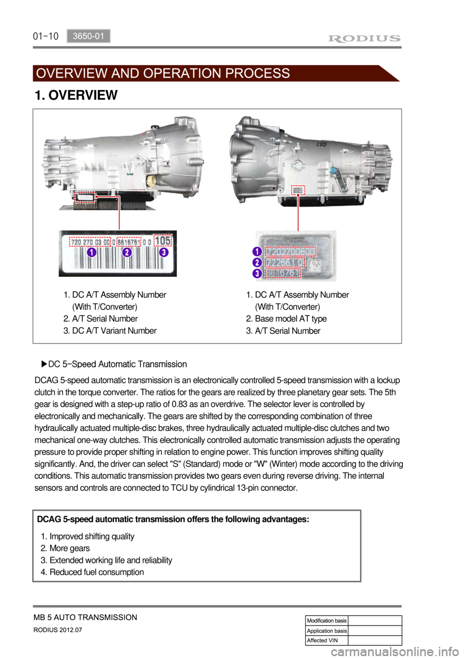
1. OVERVIEW
▶DC 5-Speed Automatic Transmission
DCAG 5-speed automatic transmission is an electronically controlled 5-speed transmission with a lockup
clutch in the torque converter. The ratios for the gears are realized by three planetary gear sets. The 5th
gear is designed with a step-up ratio of 0.83 as an overdrive. The selector lever is controlled by
electronically and mechanically. The gears are shifted by the corresponding combination of three
hydraulically actuated multiple-disc brakes, three hydraulically actuated multiple-disc clutches and two
mechanical one-way clutches. This electronically controlled automatic transmission adjusts the operating
pressure to provide proper shifting in relation to engine power. This function improves shifting quality
significantly. And, the driver can select "S" (Standard) mode or "W" (Winter) mode according to the driving
conditions. This automatic transmission provides two gears even during reverse driving. The internal
sensors and controls are connected to TCU by cylindrical 13-pin connector.
DCAG 5-speed automatic transmission offers the following advantages:
Improved shifting quality
More gears
Extended working life and reliability
Reduced fuel consumption 1.
2.
3.
4.
DC A/T Assembly Number
(With T/Converter)
A/T Serial Number
DC A/T Variant Number 1.
2.
3.DC A/T Assembly Number
(With T/Converter)
Base model AT type
A/T Serial Number 1.
2.
3.
Page 623 of 715

09-154891-01
4. SCHEMATIC DIAGRAM
When equipped with ABS, the braking force at each wheel will be controlled with 3-channel 4-
sensor method. And when equipped with ESP, 4 wheels will be controlled independently with 4-
channel method. (When controlling ABS system only, it will be operated with 3-channel method.)
When compared to the vehicle equipped with ABS/EBD only, the internal hydraulic circuit has a
normally-open separation valve and a shuttle valve in primary circuit and in secondary circuit.
When the vehicle brakes are not applied during engine running or when applying the non-ABS
operating brakes, the normally-open separation valve and the inlet valve are open, whereas the
normally-closed shuttle valve and the outlet valve are closed. When the ESP system is operating,
the normally-open separation valve will be closed by the solenoid valve operation and the hydraulic
circuit will be established by the shuttle valve. Then, the inlet and outlet valves will be
closed or open depending on the braking pressure increase, decrease or unchanged conditions.
▶The warning lamp comes on and warning beep sounds when the ESP is operating
Driving feeling when the ESP is operating ▶
▶Noise and vibration that driver senses when the ESP is operating
1) Hydraulic Circuit Diagram
When the ESP operates during vehicle movement, the ESP warning lamp on the instrument
panel flickers and beep comes on every 0.1 seconds. The ESP operation shows that the vehicle
stability is extremely unstable and it is used to warn the driver. The ESP system is just a
supplementary system for the vehicle motion and it cannot control the vehicle when it exceeds
the physical limits. Do not solely rely on the system but be advised to drive the vehicle safely.
When the ESP system activates, the driving feeling can be different depending on vehicle
driving conditions. For example, you will feel differently when the ESP system is activated during
when ABS is operating with the brakes applied and when brakes are not applied on a curve.
Thus, the ESP system would make the driver feel more abruptly when the brakes are applied
during the ESP system activation.
The ESP system may transfer noise and vibration to the driver due to the pressure changes
caused by the motor and valve operations in a very short period of time. Extreme cornering will
trigger the ESP operation and this will make the driver feel noise and vibration due to sudden
brake application. Also, the ESP system controls the engine output. So, the driver may notice
the engine output decrease even when the accelerator pedal is being applied.
Page 624 of 715

09-16
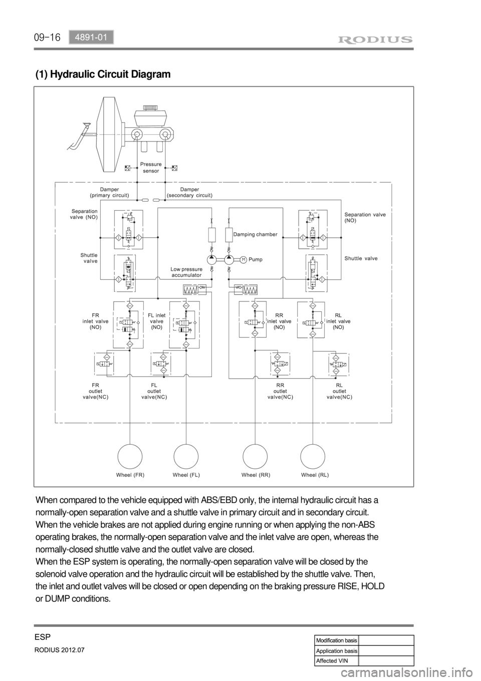
(1) Hydraulic Circuit Diagram
When compared to the vehicle equipped with ABS/EBD only, the internal hydraulic circuit has a
normally-open separation valve and a shuttle valve in primary circuit and in secondary circuit.
When the vehicle brakes are not applied during engine running or when applying the non-ABS
operating brakes, the normally-open separation valve and the inlet valve are open, whereas the
normally-closed shuttle valve and the outlet valve are closed.
When the ESP system is operating, the normally-open separation valve will be closed by the
solenoid valve operation and the hydraulic circuit will be established by the shuttle valve. Then,
the inlet and outlet valves will be closed or open depending on the braking pressure RISE, HOLD
or DUMP conditions.
Page 636 of 715

10-74891-01
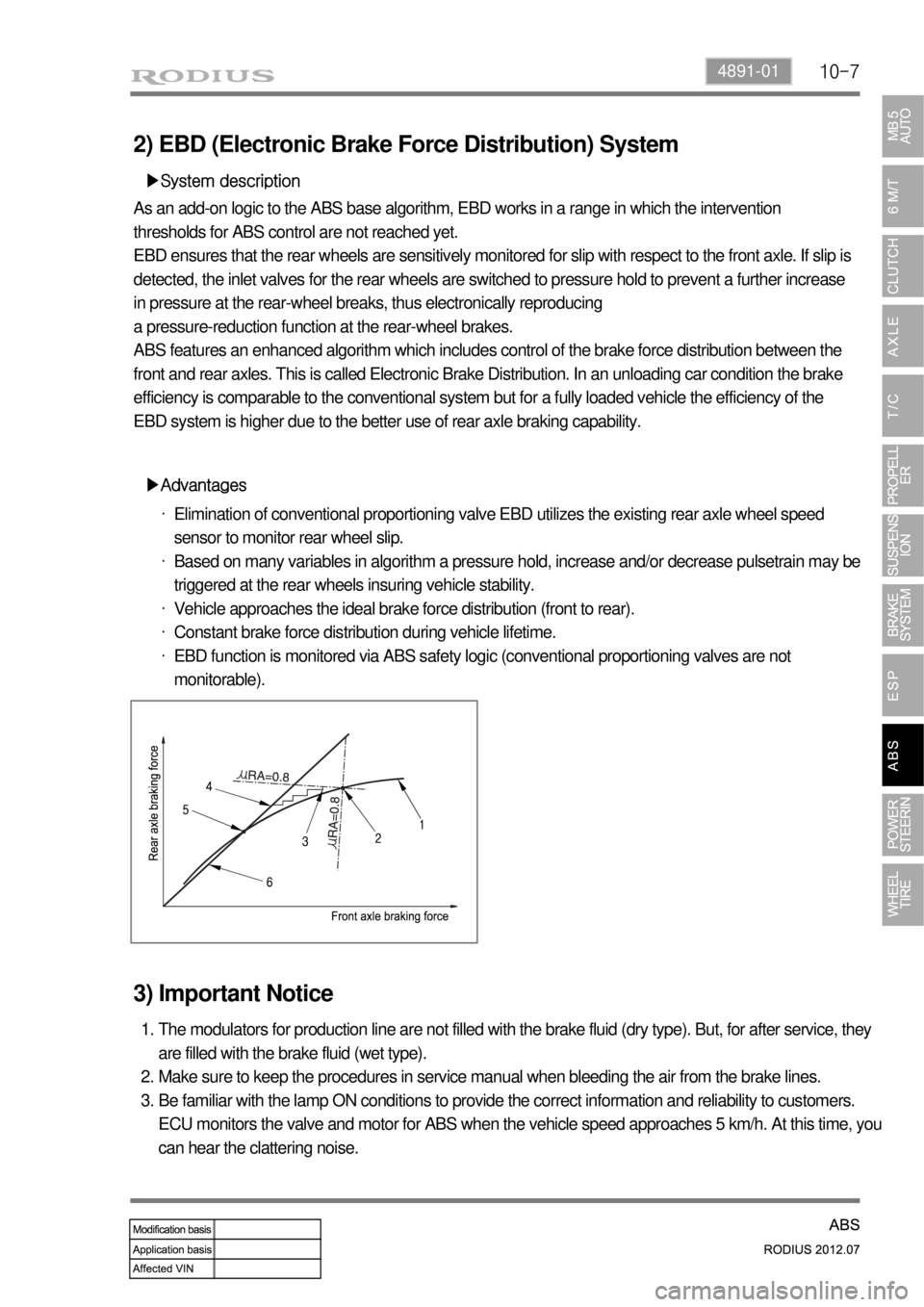
2) EBD (Electronic Brake Force Distribution) System
▶System description
As an add-on logic to the ABS base algorithm, EBD works in a range in which the intervention
thresholds for ABS control are not reached yet.
EBD ensures that the rear wheels are sensitively monitored for slip with respect to the front axle. If slip is
detected, the inlet valves for the rear wheels are switched to pressure hold to prevent a further increase
in pressure at the rear-wheel breaks, thus electronically reproducing
a pressure-reduction function at the rear-wheel brakes.
ABS features an enhanced algorithm which includes control of the brake force distribution between the
front and rear axles. This is called Electronic Brake Distribution. In an unloading car condition the brake
efficiency is comparable to the conventional system but for a fully loaded vehicle the efficiency of the
EBD system is higher due to the better use of rear axle braking capability.
▶Advantages
Elimination of conventional proportioning valve EBD utilizes the existing rear axle wheel speed
sensor to monitor rear wheel slip.
Based on many variables in algorithm a pressure hold, increase and/or decrease pulsetrain may be
triggered at the rear wheels insuring vehicle stability.
Vehicle approaches the ideal brake force distribution (front to rear).
Constant brake force distribution during vehicle lifetime.
EBD function is monitored via ABS safety logic (conventional proportioning valves are not
monitorable). ·
·
·
·
·
3) Important Notice
The modulators for production line are not filled with the brake fluid (dry type). But, for after service, they
are filled with the brake fluid (wet type).
Make sure to keep the procedures in service manual when bleeding the air from the brake lines.
Be familiar with the lamp ON conditions to provide the correct information and reliability to customers.
ECU monitors the valve and motor for ABS when the vehicle speed approaches 5 km/h. At this time, you
can hear the clattering noise. 1.
2.
3.