tow SUBARU FORESTER 2017 SJ / 4.G Owners Manual
[x] Cancel search | Manufacturer: SUBARU, Model Year: 2017, Model line: FORESTER, Model: SUBARU FORESTER 2017 SJ / 4.GPages: 634, PDF Size: 11.77 MB
Page 17 of 634
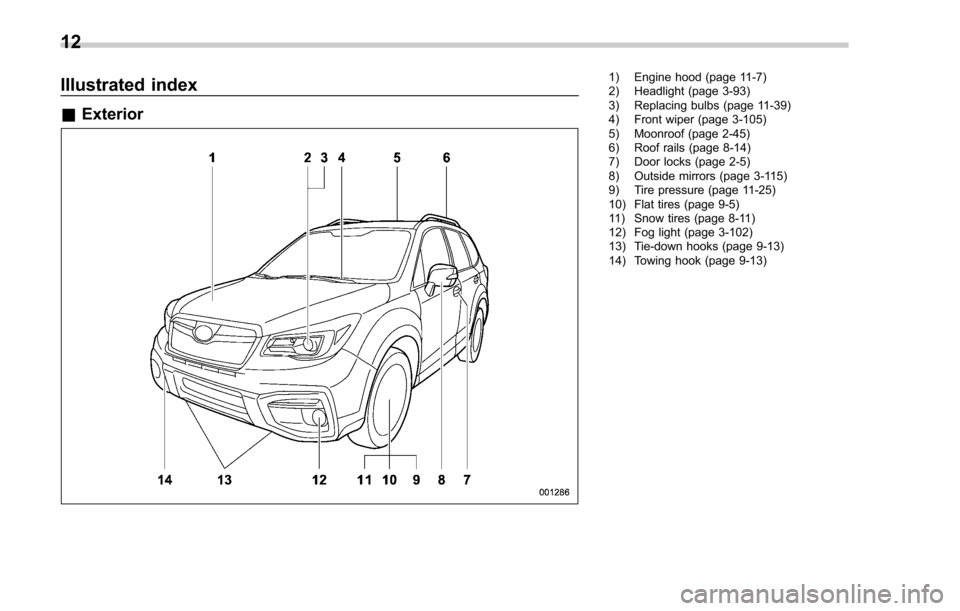
Illustrated index
&Exterior
1) Engine hood (page 11-7)
2) Headlight (page 3-93)
3) Replacing bulbs (page 11-39)
4) Front wiper (page 3-105)
5) Moonroof (page 2-45)
6) Roof rails (page 8-14)
7) Door locks (page 2-5)
8) Outside mirrors (page 3-115)
9) Tire pressure (page 11-25)
10) Flat tires (page 9-5)
11) Snow tires (page 8-11)
12) Fog light (page 3-102)
13) Tie-down hooks (page 9-13)
14) Towing hook (page 9-13)
12
Page 18 of 634
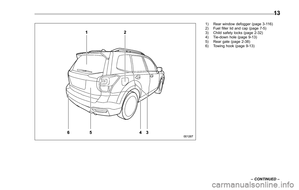
1) Rear window defogger (page 3-116)
2) Fuel filler lid and cap (page 7-5)
3) Child safety locks (page 2-32)
4) Tie-down hole (page 9-13)
5) Rear gate (page 2-38)
6) Towing hook (page 9-13)–CONTINUED –
13
Page 53 of 634
Seat, seatbelt and SRS airbags/Seatbelts
WARNING
.Be sure to fasten both tongue
plates to the respective buckles.
If the seatbelt is used only as a
shoulder belt (with the connec-
tor ’s tongue plate not fastened to
the connector ’s buckle on the
right-hand side), it cannot prop-
erly restrain the wearer in posi-
tion in an accident, possibly
resulting in serious injury or
death.
. The head restraint is not intended
to be used at the lowest position.
Before sitting on the seat, raise
the head restraint to the ex-
tended position. Otherwise, in
an accident, serious injury or
death could result.
. Before fastening the seatbelt,
confirm that the seatbelt is rou-
ted through the belt guide. A
seatbelt not routed through the
belt guide can cause neck inju-
ries during sudden braking or in
a collision since it may slip up on
your neck.
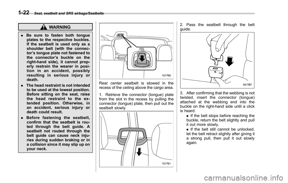
Rear center seatbelt is stowed in the
recess of the ceiling above the cargo area.
1. Retrieve the connector (tongue) plate
from the slot in the recess by pulling the
connector (tongue) plate, then pull out the
seatbelt slowly.
2. Pass the seatbelt through the belt
guide.
3. After confirming that the webbing is not
twisted, insert the connector (tongue)
attached at the webbing end into the
buckle on the right-hand side until a click
is heard.
.If the belt stops before reaching the
buckle, return the belt slightly and pull
it out more slowly.
. If the belt still cannot be unlocked,
let the belt retract slightly after giving it
a strong pull, then pull it out slowly
again.
1-22
Page 75 of 634
Seat, seatbelt and SRS airbags/*SRS airbag (Supplemental Restraint System airbag)
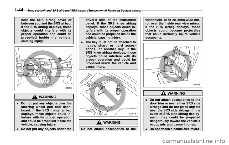
near the SRS airbag cover or
between you and the SRS airbag.
If the SRS airbag deploys, these
objects could interfere with its
proper operation and could be
propelled inside the vehicle,
causing injury.
WARNING
.Do not put any objects over the
steering wheel pad and dash-
board. If the SRS frontal airbag
deploys, these objects could in-
terfere with its proper operation
and could be propelled inside the
vehicle, causing injury.
. Do not put any objects under the driver
’s side of the instrument
panel. If the SRS knee airbag
deploys, those objects could in-
terfere with its proper operation
and could be propelled inside the
vehicle, causing injury.
. The key must not be attached to
heavy, sharp or hard acces-
sories, or another key. If the
SRS knee airbag deploys, those
objects could interfere with its
proper operation and could be
propelled inside the vehicle and
cause injury.
WARNING
Do not attach accessories to the windshield, or fit an extra-wide mir-
ror over the inside rear view mirror.
If the SRS airbag deploys, those
objects could become projectiles
that could seriously injure vehicle
occupants.
WARNING
.
Do not attach accessories to the
door trim or near either SRS side
airbags and do not place objects
near the SRS side airbags. In the
event of SRS side airbag deploy-
ment, they could be propelled
dangerously toward the vehicle ’s
occupants and cause injuries.
. Do not attach a hands-free micro-
1-44
Page 80 of 634
&Components
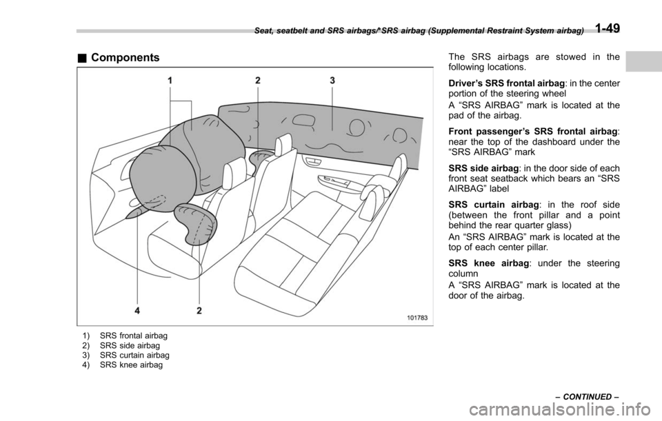
1) SRS frontal airbag
2) SRS side airbag
3) SRS curtain airbag
4) SRS knee airbag
The SRS airbags are stowed in the
following locations.
Driver ’s SRS frontal airbag : in the center
portion of the steering wheel
A “SRS AIRBAG ”mark is located at the
pad of the airbag.
Front passenger ’s SRS frontal airbag :
near the top of the dashboard under the
“SRS AIRBAG” mark
SRS side airbag : in the door side of each
front seat seatback which bears an “SRS
AIRBAG ”label
SRS curtain airbag : in the roof side
(between the front pillar and a point
behind the rear quarter glass)
An “SRS AIRBAG” mark is located at the
top of each center pillar.
SRS knee airbag : under the steering
column
A “SRS AIRBAG ”mark is located at the
door of the airbag.
Seat, seatbelt and SRS airbags/*SRS airbag (Supplemental Restraint System airbag)
–CONTINUED –1-49
Page 109 of 634
Keys and doors/Door locks
the“ON ”position.
For details about the alarm system,
refer to “Alarm system ”F 2-25.
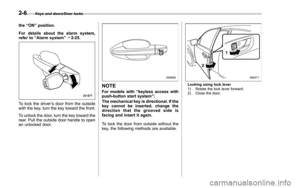
To lock the driver ’s door from the outside
with the key, turn the key toward the front.
To unlock the door, turn the key toward the
rear. Pull the outside door handle to open
an unlocked door.
NOTE
For models with “keyless access with
push-button start system ”:
The mechanical key is directional. If the
key cannot be inserted, change the
direction that the grooved side is
facing and insert it again.
To lock the door from outside without the
key, the following methods are available.
Locking using lock lever
1) Rotate the lock lever forward.
2) Close the door.
2-6
Page 116 of 634
&Locking and unlocking with
“keyless access ”entry func-
tion
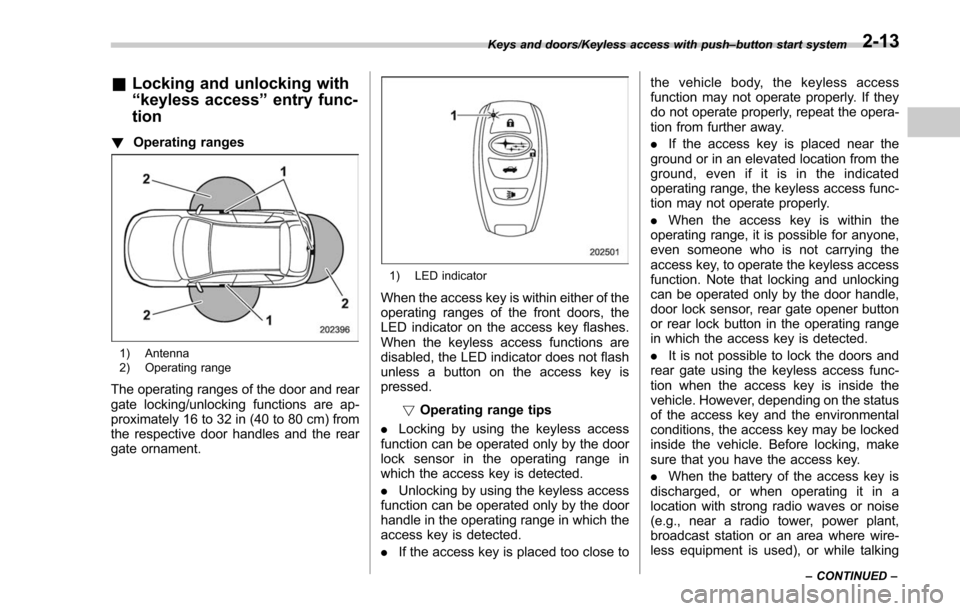
! Operating ranges
1) Antenna
2) Operating range
The operating ranges of the door and rear
gate locking/unlocking functions are ap-
proximately 16 to 32 in (40 to 80 cm) from
the respective door handles and the rear
gate ornament.
1) LED indicator
When the access key is within either of the
operating ranges of the front doors, the
LED indicator on the access key flashes.
When the keyless access functions are
disabled, the LED indicator does not flash
unless a button on the access key is
pressed.
!Operating range tips
. Locking by using the keyless access
function can be operated only by the door
lock sensor in the operating range in
which the access key is detected.
. Unlocking by using the keyless access
function can be operated only by the door
handle in the operating range in which the
access key is detected.
. If the access key is placed too close to the vehicle body, the keyless access
function may not operate properly. If they
do not operate properly, repeat the opera-
tion from further away.
.
If the access key is placed near the
ground or in an elevated location from the
ground, even if it is in the indicated
operating range, the keyless access func-
tion may not operate properly.
. When the access key is within the
operating range, it is possible for anyone,
even someone who is not carrying the
access key, to operate the keyless access
function. Note that locking and unlocking
can be operated only by the door handle,
door lock sensor, rear gate opener button
or rear lock button in the operating range
in which the access key is detected.
. It is not possible to lock the doors and
rear gate using the keyless access func-
tion when the access key is inside the
vehicle. However, depending on the status
of the access key and the environmental
conditions, the access key may be locked
inside the vehicle. Before locking, make
sure that you have the access key.
. When the battery of the access key is
discharged, or when operating it in a
location with strong radio waves or noise
(e.g., near a radio tower, power plant,
broadcast station or an area where wire-
less equipment is used), or while talking
Keys and doors/Keyless access with push –button start system
–CONTINUED –2-13
Page 125 of 634
Keys and doors/Remote keyless entry system
l’utilisateur de l ’appareil doit accepter
tout brouillage radioélectrique subi,
même si le brouillage est susceptible
d ’en compromettre le fonctionnement.
For models with “keyless access with
push-button start system ”, the access
key is used as the transmitter for the
remote keyless entry system. For models
without “keyless access with push-button
start system” , the transmitter for the
remote keyless entry system is located
inside the key head.
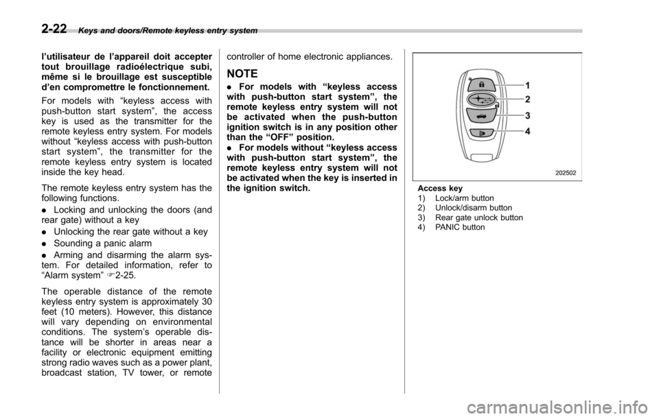
The remote keyless entry system has the
following functions.
. Locking and unlocking the doors (and
rear gate) without a key
. Unlocking the rear gate without a key
. Sounding a panic alarm
. Arming and disarming the alarm sys-
tem. For detailed information, refer to
“Alarm system ”F 2-25.
The operable distance of the remote
keyless entry system is approximately 30
feet (10 meters). However, this distance
will vary depending on environmental
conditions. The system ’s operable dis-
tance will be shorter in areas near a
facility or electronic equipment emitting
strong radio waves such as a power plant,
broadcast station, TV tower, or remote controller of home electronic appliances.
NOTE
.
For models with “keyless access
with push-button start system ”,the
remote keyless entry system will not
be activated when the push-button
ignition switch is in any position other
than the “OFF ”position.
. For models without “keyless access
with push-button start system ”,the
remote keyless entry system will not
be activated when the key is inserted in
the ignition switch.
Access key
1) Lock/arm button
2) Unlock/disarm button
3) Rear gate unlock button
4) PANIC button
2-22
Page 155 of 634
Instruments and controls/Ignition switch (models without push–button start system)
Ignition switch (models with-
out push-button start sys-
tem)
WARNING
. Never turn the ignition switch to
the “LOCK ”position while the
vehicle is being driven or towed
because that will lock the steer-
ing wheel, preventing steering
control. And when the engine is
turned off, it takes a much great-
er effort than usual to steer.
. Before leaving the vehicle, al-
ways remove the key from the
ignition switch for safety and
never allow an unattended child
to remain in the vehicle. Failure
to follow this procedure could
result in injury to a child or
others. Children could operate
the power windows, the moon-
roof or other controls or even
make the vehicle move.
CAUTION
Do not attach a large key holder or
key case to either key. If it banged
against your knees or hands while
you are driving, it could turn the
ignition switch from the “ON ”posi-
tion to the “ACC ”or “LOCK ”posi-
tion, thereby stopping the engine.
Also, if the key is attached to a
keyholder or to a large bunch of
other keys, centrifugal force may act
on it as the vehicle moves, resulting
in unwanted turning of the ignition
switch.
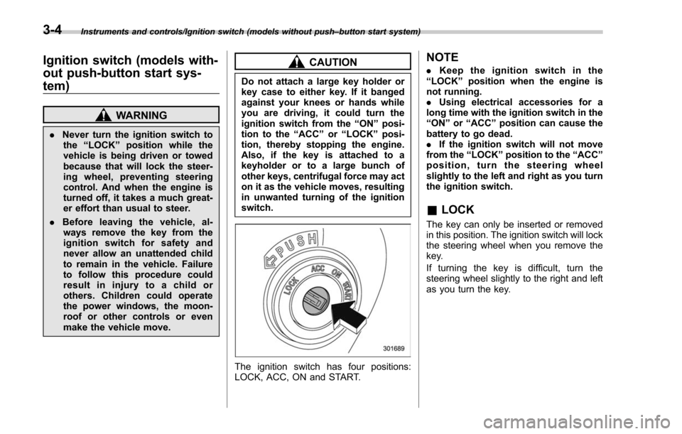
The ignition switch has four positions:
LOCK, ACC, ON and START.
NOTE
. Keep the ignition switch in the
“ LOCK ”position when the engine is
not running.
. Using electrical accessories for a
long time with the ignition switch in the
“ ON ”or “ACC ”position can cause the
battery to go dead.
. If the ignition switch will not move
from the “LOCK ”position to the “ACC ”
position, turn the steering wheel
slightly to the left and right as you turn
the ignition switch.
& LOCK
The key can only be inserted or removed
in this position. The ignition switch will lock
the steering wheel when you remove the
key.
If turning the key is difficult, turn the
steering wheel slightly to the right and left
as you turn the key.
3-4
Page 163 of 634
Instruments and controls/Meters and gauges
&Fuel gauge
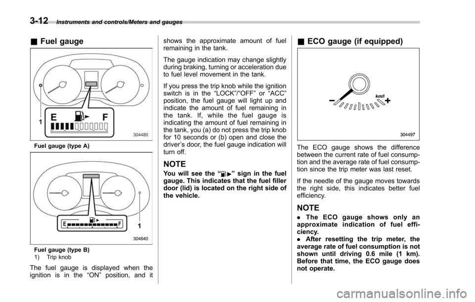
Fuel gauge (type A)
Fuel gauge (type B)
1) Trip knob
The fuel gauge is displayed when the
ignition is in the “ON”position, and it shows the approximate amount of fuel
remaining in the tank.
The gauge indication may change slightly
during braking, turning or acceleration due
to fuel level movement in the tank.
If you press the trip knob while the ignition
switch is in the
“LOCK”/ “OFF”or “ACC ”
position, the fuel gauge will light up and
indicate the amount of fuel remaining in
the tank. If, while the fuel gauge is
indicating the amount of fuel remaining in
the tank, you (a) do not press the trip knob
for 10 seconds or (b) open and close the
driver ’s door, the fuel gauge indication will
turn off.
NOTE
You will see the “”sign in the fuel
gauge. This indicates that the fuel filler
door (lid) is located on the right side of
the vehicle.
& ECO gauge (if equipped)
The ECO gauge shows the difference
between the current rate of fuel consump-
tion and the average rate of fuel consump-
tion since the trip meter was last reset.
If the needle of the gauge moves towards
the right side, this indicates better fuel
efficiency.
NOTE
. The ECO gauge shows only an
approximate indication of fuel effi-
ciency.
. After resetting the trip meter, the
average rate of fuel consumption is not
shown until driving 0.6 mile (1 km).
Before that time, the ECO gauge does
not operate.
3-12