ac 25 procedure SUBARU TRIBECA 2009 1.G Service Owners Manual
[x] Cancel search | Manufacturer: SUBARU, Model Year: 2009, Model line: TRIBECA, Model: SUBARU TRIBECA 2009 1.GPages: 2453, PDF Size: 46.32 MB
Page 468 of 2453
LAN(diag)-12
Subaru Select Monitor
LAN SYSTEM (DIAGNOSTICS)
6. Subaru Select Monitor
A: OPERATION
1. READ DIAGNOSTIC TROUBLE CODE
(DTC)
NOTE:
•DTC is displayed in the sequence of inputting.
(When inputting two DTCs or more simultaneously,
they are displayed in the sequence of priority.)
•When more than two DTCs are displayed, per-
form the diagnosis of top of them.
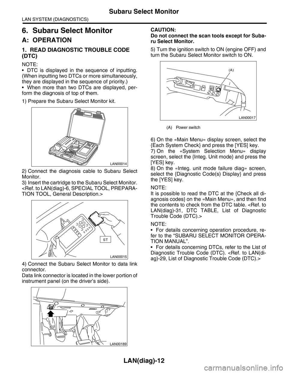
1) Prepare the Subaru Select Monitor kit.
2) Connect the diagnosis cable to Subaru Select
Monitor.
3) Insert the cartridge to the Subaru Select Monitor.
4) Connect the Subaru Select Monitor to data link
connector.
Data link connector is located in the lower portion of
instrument panel (on the driver’s side).
CAUTION:
Do not connect the scan tools except for Suba-
ru Select Monitor.
5) Turn the ignition switch to ON (engine OFF) and
turn the Subaru Select Monitor switch to ON.
6) On the «Main Menu» display screen, select the
{Each System Check} and press the [YES] key.
7) On the «System Selection Menu» display
screen, select the {Integ. Unit mode} and press the
[YES] key.
8) On the «Integ. unit mode failure diag» screen,
select the {Diagnostic Code(s) Display} and press
the [YES] key.
NOTE:
It is possible to read the DTC at the {Check all di-
agnosis codes} on the «Main Menu», and then find
the contents to check from the DTC table.
Trouble Code (DTC).>
NOTE:
•For details concerning operation procedure, re-
fer to the “SUBARU SELECT MONITOR OPERA-
TION MANUAL”.
•For details concerning DTCs, refer to the List of
Diagnostic Trouble Code (DTC).
LAN00014
LAN00015
ST
LAN00189
(A) Power switch
LAN00017
(A)
Page 473 of 2453
LAN(diag)-17
Subaru Select Monitor
LAN SYSTEM (DIAGNOSTICS)
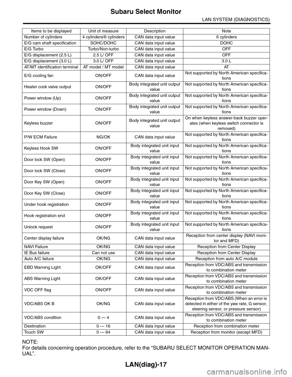
NOTE:
For details concerning operation procedure, refer to the “SUBARU SELECT MONITOR OPERATION MAN-
UAL”.
Number of cylinders 4 cylinders/6 cylinders CAN data input value 6 cylinders
E/G cam shaft specification SOHC/DOHC CAN data input value DOHC
E/G Turbo Turbo/Non-turbo CAN data input value OFF
E/G displacement (2.5 L) 2.5 L/ OFF CAN data input value OFF
E/G displacement (3.0 L) 3.0 L/ OFF CAN data input value 3.0 L
AT / M T i d e n t i f i c a t i o n t e r m i n a l AT m o d e l / M T m o d e l C A N d a t a i n p u t v a l u e AT
E/G cooling fan ON/OFF CAN data input valueNot supported by North American specifica-
tions
Heater cock valve output ON/OFFBody integrated unit output
value
Not supported by North American specifica-
tions
Pow er w i nd ow (U p) O N /O FFBody integrated unit output
value
Not supported by North American specifica-
tions
Pow er w i nd ow (D ow n ) O N /O FFBody integrated unit output
value
Not supported by North American specifica-
tions
Keyless buzzer ON/OFFBody integrated unit output
value
On when keyless answer-back buzzer oper-
ates (when keyless switch connector is
removed)
P/W ECM Failure NG/OK CAN data input valueNot supported by North American specifica-
tions
Keyless Hook SW ON/OFFBody integrated unit input
value
Not supported by North American specifica-
tions
Door lock SW (Open) ON/OFFBody integrated unit input
value
Not supported by North American specifica-
tions
Door lock SW (Close) ON/OFFBody integrated unit input
value
Not supported by North American specifica-
tions
Door Key SW (Open) ON/OFFBody integrated unit input
value
Not supported by North American specifica-
tions
Door Key SW (Close) ON/OFFBody integrated unit input
value
Not supported by North American specifica-
tions
Under hook registration ON/OFFBody integrated unit input
value
Not supported by North American specifica-
tions
Hook registration end ON/OFFBody integrated unit input
value
Not supported by North American specifica-
tions
Unlock request ON/OFFBody integrated unit input
value
Not supported by North American specifica-
tions
Center display failure OK/NG CAN data input valueReception from center display (NAVI moni-
tor and MFD)
NAVI Failure OK/NG CAN data input value Reception from Center Display
IE Bus failure Can not use CAN data input value Reception from Center Display
Auto A/C failure OK/NG C AN data input value Reception from auto A/C module
EBD Warning Light OK/OFF CAN data input valueReception from VDC/ABS and transmission
to combination meter
ABS Warning Light OK/OFF CAN data input valueReception from VDC/ABS and transmission
to combination meter
VDC OFF flag ON/OFF CAN data input valueReception from VDC/ABS and transmission
to combination meter
VDC/ABS OK B OK/NG CAN data input value
Reception from VDC/ABS (When an error is
detected in either of the yaw rate, G sensor,
steering sensor, or pressure sensor)
VDC/ABS condition 0 — 4 CAN data input valueReception from VDC/ABS and transmission
to combination meter
Destination 0 — 16 CAN data input value Reception from combination meter
To u c h S W 0 — 6 4 C A N d a t a i n p u t v a l u e R e c e p t i o n f r o m m o n i t o r ( e x c e p t M F D )
Items to be displayed Unit of measure Description Note
Page 476 of 2453
LAN(diag)-20
Subaru Select Monitor
LAN SYSTEM (DIAGNOSTICS)
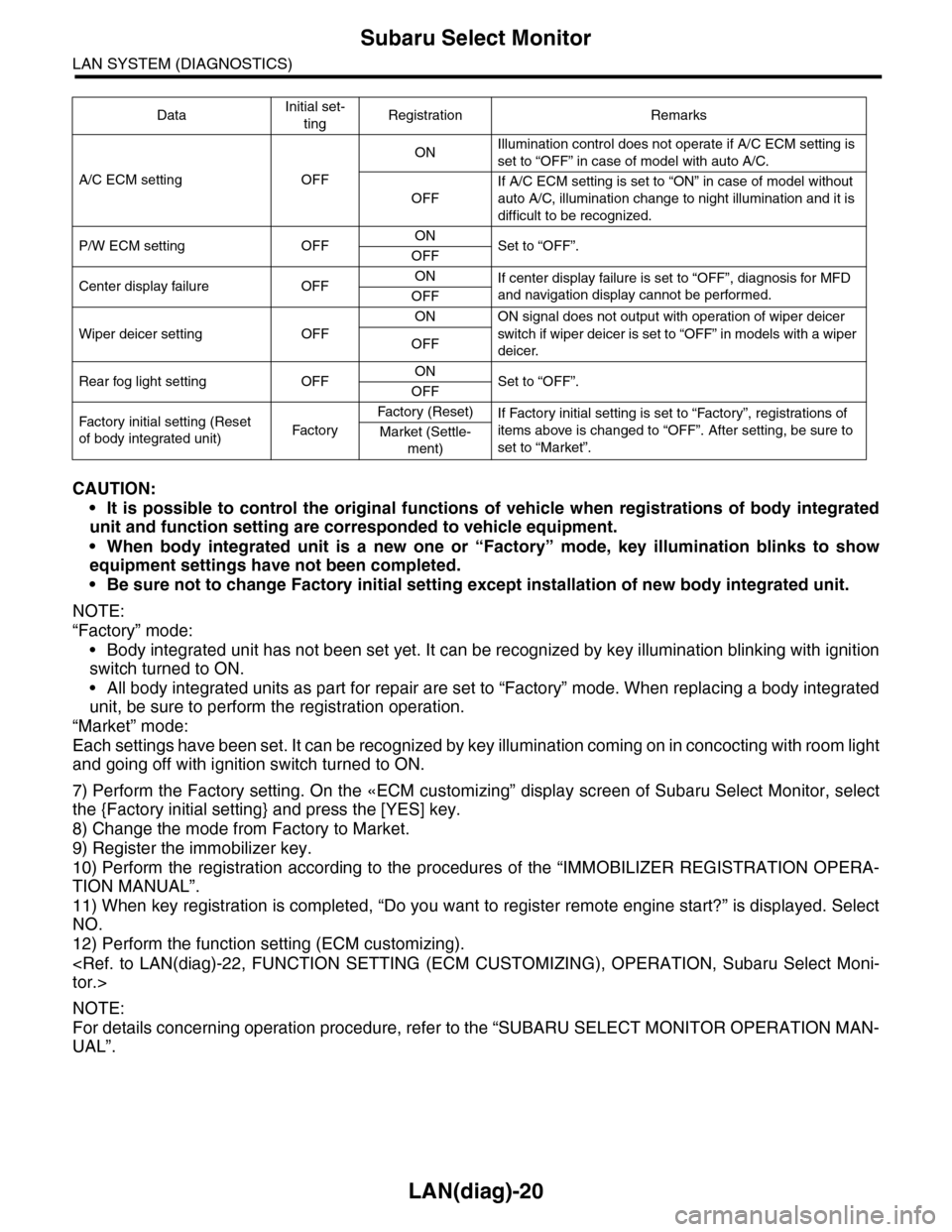
CAUTION:
•It is possible to control the original functions of vehicle when registrations of body integrated
unit and function setting are corresponded to vehicle equipment.
•When body integrated unit is a new one or “Factory” mode, key illumination blinks to show
equipment settings have not been completed.
•Be sure not to change Factory initial setting except installation of new body integrated unit.
NOTE:
“Factory” mode:
•Body integrated unit has not been set yet. It can be recognized by key illumination blinking with ignition
switch turned to ON.
•All body integrated units as part for repair are set to “Factory” mode. When replacing a body integrated
unit, be sure to perform the registration operation.
“Market” mode:
Each settings have been set. It can be recognized by key illumination coming on in concocting with room light
and going off with ignition switch turned to ON.
7) Perform the Factory setting. On the «ECM customizing” display screen of Subaru Select Monitor, select
the {Factory initial setting} and press the [YES] key.
8) Change the mode from Factory to Market.
9) Register the immobilizer key.
10) Perform the registration according to the procedures of the “IMMOBILIZER REGISTRATION OPERA-
TION MANUAL”.
11) When key registration is completed, “Do you want to register remote engine start?” is displayed. Select
NO.
12) Perform the function setting (ECM customizing).
NOTE:
For details concerning operation procedure, refer to the “SUBARU SELECT MONITOR OPERATION MAN-
UAL”.
DataInitial set-
tingRegistration Remarks
A/C ECM setting OFF
ONIllumination control does not operate if A/C ECM setting is
set to “OFF” in case of model with auto A/C.
OFF
If A/C ECM setting is set to “ON” in case of model without
auto A/C, illumination change to night illumination and it is
difficult to be recognized.
P/W ECM setting OFFONSet to “OFF”.OFF
Center display failure OFFONIf center display failure is set to “OFF”, diagnosis for MFD
and navigation display cannot be performed.OFF
Wiper deicer setting OFF
ON ON signal does not output with operation of wiper deicer
switch if wiper deicer is set to “OFF” in models with a wiper
deicer.OFF
Rear fog light setting OFFONSet to “OFF”.OFF
Fac t or y in i ti a l s et t i ng ( Res et
of body integrated unit)Fac to r y
Fa ct or y ( Re se t )If Factory initial setting is set to “Factory”, registrations of
items above is changed to “OFF”. After setting, be sure to
set to “Market”.Market (Settle-
ment)
Page 477 of 2453
![SUBARU TRIBECA 2009 1.G Service Owners Manual LAN(diag)-21
Subaru Select Monitor
LAN SYSTEM (DIAGNOSTICS)
7. CLEAR MEMORY MODE
1) On the «Main Menu» display screen, select the
{2. Each System Check} and press the [YES] key.
2) On the «System SUBARU TRIBECA 2009 1.G Service Owners Manual LAN(diag)-21
Subaru Select Monitor
LAN SYSTEM (DIAGNOSTICS)
7. CLEAR MEMORY MODE
1) On the «Main Menu» display screen, select the
{2. Each System Check} and press the [YES] key.
2) On the «System](/img/17/7322/w960_7322-476.png)
LAN(diag)-21
Subaru Select Monitor
LAN SYSTEM (DIAGNOSTICS)
7. CLEAR MEMORY MODE
1) On the «Main Menu» display screen, select the
{2. Each System Check} and press the [YES] key.
2) On the «System Selection Menu» display
screen, select the {Integ. Unit mode} and press the
[YES] key.
3) Press the [YES] key after the information of body
integrated unit type is displayed.
4) On the «Integ. Unit mode failure diag» display
screen, select the {Clear Memory} and press the
[YES] key.
5) When “Done” is shown on the display screen,
turn the ignition switch to OFF.
NOTE:
For details concerning operation procedure, refer
to the “SUBARU SELECT MONITOR OPERATION
MANUAL”.
8. FREEZE FRAME DATA
NOTE:
•Data stored at the time of trouble occurrence is
shown on display.
•Freeze frame data will be memorized maximum
to 20.
•If freeze frame data is not stored in memory cor-
rectly (caused by low power supply of body inte-
grated unit), DTC will be displayed with “?” on the
head of it in the Subaru Select Monitor display. This
shows it may be an unreliable reading.
Display Contents to be monitored
Clear memory?Clear function of DTC and
freeze frame data
Page 479 of 2453
LAN(diag)-23
Subaru Select Monitor
LAN SYSTEM (DIAGNOSTICS)
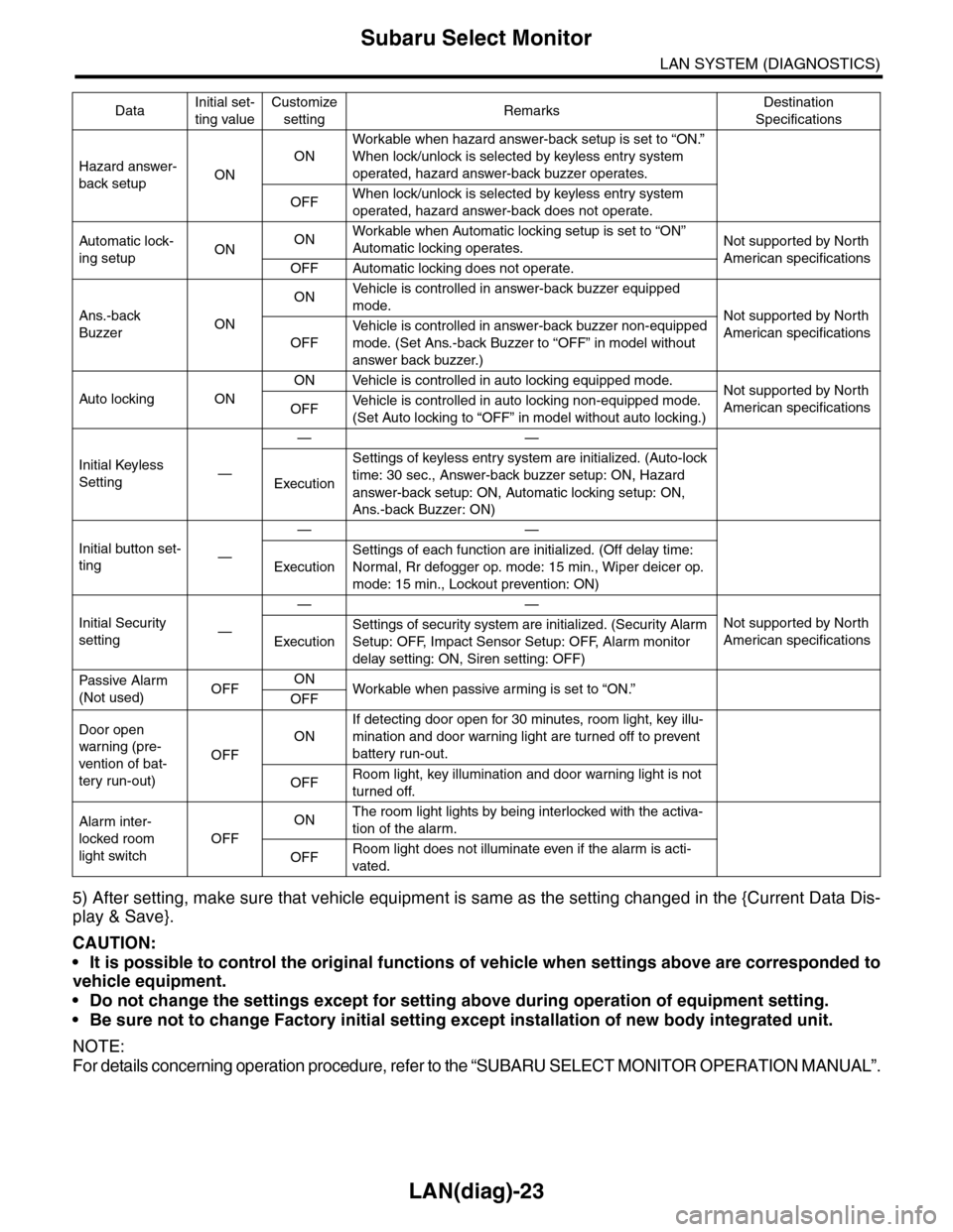
5) After setting, make sure that vehicle equipment is same as the setting changed in the {Current Data Dis-
play & Save}.
CAUTION:
•It is possible to control the original functions of vehicle when settings above are corresponded to
vehicle equipment.
•Do not change the settings except for setting above during operation of equipment setting.
•Be sure not to change Factory initial setting except installation of new body integrated unit.
NOTE:
For details concerning operation procedure, refer to the “SUBARU SELECT MONITOR OPERATION MANUAL”.
Hazard answer-
back setupON
ON
Workable when hazard answer-back setup is set to “ON.”
When lock/unlock is selected by keyless entry system
operated, hazard answer-back buzzer operates.
OFFWhen lock/unlock is selected by keyless entry system
operated, hazard answer-back does not operate.
Automatic lock-
ing setupONONWorkable when Automatic locking setup is set to “ON”
Automatic locking operates.Not supported by North
American specificationsOFF Automatic locking does not operate.
Ans.-back
BuzzerON
ONVe h i c l e i s c o n t r o l l e d i n a n sw e r - b a c k b u z z e r e q u i p p e d
mode.Not supported by North
American specificationsOFF
Ve h i c l e i s c o n t r o l l e d i n a n sw e r - b a c k b u z z e r n o n - e q u i p p e d
mode. (Set Ans.-back Buzzer to “OFF” in model without
answer back buzzer.)
Auto locking ON
ON Vehicle is controlled in auto locking equipped mode.Not supported by North
American specificationsOFFVe h i c l e i s c o n t r o l l e d i n a u t o l o c k i n g n o n - e q u i p p e d m o d e .
(Set Auto locking to “OFF” in model without auto locking.)
Initial Keyless
Setting—
——
Execution
Settings of keyless entry system are initialized. (Auto-lock
time: 30 sec., Answer-back buzzer setup: ON, Hazard
answer-back setup: ON, Automatic locking setup: ON,
Ans.-back Buzzer: ON)
Initial button set-
ting—
——
Execution
Settings of each function are initialized. (Off delay time:
Normal, Rr defogger op. mode: 15 min., Wiper deicer op.
mode: 15 min., Lockout prevention: ON)
Initial Security
setting—
——
Not supported by North
American specificationsExecution
Settings of security system are initialized. (Security Alarm
Setup: OFF, Impact Sensor Setup: OFF, Alarm monitor
delay setting: ON, Siren setting: OFF)
Passive Alar m
(Not used)OFFONWorkable when passive ar ming is set to “ON.”
OFF
Door open
warning (pre-
vention of bat-
tery run-out)
OFF
ON
If detecting door open for 30 minutes, room light, key illu-
mination and door warning light are turned off to prevent
battery run-out.
OFFRoom light, key illumination and door warning light is not
turned off.
Alarm inter-
locked room
light switch
OFF
ONThe room light lights by being interlocked with the activa-
tion of the alarm.
OFFRoom light does not illuminate even if the alarm is acti-
vated.
DataInitial set-
ting value
Customize
settingRemarksDestination
Specifications
Page 481 of 2453
LAN(diag)-25
Read Diagnostic Trouble Code (DTC)
LAN SYSTEM (DIAGNOSTICS)
7. Read Diagnostic Trouble
Code (DTC)
A: OPERATION
For details concerning DTC reading procedure, re-
fer to “Subaru Select Monitor”.
OPERATION, Subaru Select Monitor.>
Page 484 of 2453
LAN(diag)-28
Function Setting (Customize)
LAN SYSTEM (DIAGNOSTICS)
10.Function Setting (Customize)
A: OPERATION
For detailed procedures of function setting (ECM
customizing), refer to “SUBARU SELECT MONI-
TOR”.
Subaru Select Monitor.>
Page 485 of 2453
LAN(diag)-29
List of Diagnostic Trouble Code (DTC)
LAN SYSTEM (DIAGNOSTICS)
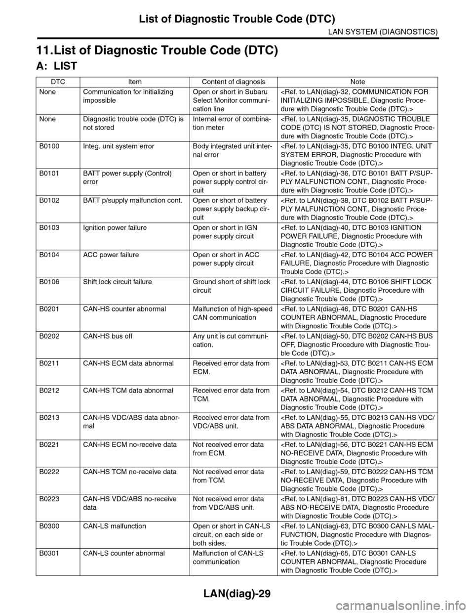
11.List of Diagnostic Trouble Code (DTC)
A: LIST
DTC Item Content of diagnosis Note
None Communication for initializing
impossible
Open or short in Subaru
Select Monitor communi-
cation line
dure with Diagnostic Trouble Code (DTC).>
None Diagnostic trouble code (DTC) is
not stored
Internal error of combina-
tion meter
dure with Diagnostic Trouble Code (DTC).>
B0100 Integ. unit system error Body integrated unit inter-
nal error
Diagnostic Trouble Code (DTC).>
B0101 BATT power supply (Control)
error
Open or short in battery
power supply control cir-
cuit
dure with Diagnostic Trouble Code (DTC).>
B0102 BATT p/supply malfunction cont. Open or short of battery
power supply backup cir-
cuit
dure with Diagnostic Trouble Code (DTC).>
B0103 Ignition power failure Open or short in IGN
power supply circuit
Diagnostic Trouble Code (DTC).>
B0104 ACC power failure Open or short in ACC
power supply circuit
Tr o u b l e C o d e ( D T C ) . >
B0106 Shift lock circuit failure Ground short of shift lock
circuit
Diagnostic Trouble Code (DTC).>
B0201 CAN-HS counter abnormal Malfunction of high-speed
CAN communication
with Diagnostic Trouble Code (DTC).>
B0202 CAN-HS bus off Any unit is cut communi-
cation.
ble Code (DTC).>
B0211 CAN-HS ECM data abnormal Received error data from
ECM.
Diagnostic Trouble Code (DTC).>
B0212 CAN-HS TCM data abnormal Received error data from
TCM.
Diagnostic Trouble Code (DTC).>
B0213 CAN-HS VDC/ABS data abnor-
mal
Received error data from
VDC/ABS unit.
with Diagnostic Trouble Code (DTC).>
B0221 CAN-HS ECM no-receive data Not received error data
from ECM.
Diagnostic Trouble Code (DTC).>
B0222 CAN-HS TCM no-receive data Not received error data
from TCM.
Diagnostic Trouble Code (DTC).>
B0223 CAN-HS VDC/ABS no-receive
data
Not received error data
from VDC/ABS unit.
with Diagnostic Trouble Code (DTC).>
B0300 CAN-LS malfunction Open or short in CAN-LS
circuit, on each side or
both sides.
tic Trouble Code (DTC).>
B0301 CAN-LS counter abnormal Malfunction of CAN-LS
communication
with Diagnostic Trouble Code (DTC).>
Page 486 of 2453
LAN(diag)-30
List of Diagnostic Trouble Code (DTC)
LAN SYSTEM (DIAGNOSTICS)
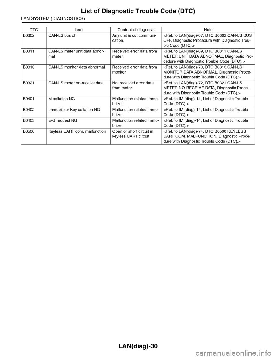
B0302 CAN-LS bus off Any unit is cut communi-
cation.
ble Code (DTC).>
B0311 CAN-LS meter unit data abnor-
mal
Received error data from
meter.
cedure with Diagnostic Trouble Code (DTC).>
B0313 CAN-LS monitor data abnormal Received error data from
monitor.
dure with Diagnostic Trouble Code (DTC).>
B0321 CAN-LS meter no-receive data Not received error data
from meter.
dure with Diagnostic Trouble Code (DTC).>
B0401 M collation NG Malfunction related immo-
bilizer
B0402 Immobilizer Key collation NG Malfunction related immo-
bilizer
B0403 E/G request NG Malfunction related immo-
bilizer
B0500 Keyless UART com. malfunction Open or short circuit in
keyless UART circuit
dure with Diagnostic Trouble Code (DTC).>
DTC Item Content of diagnosis Note
Page 487 of 2453
LAN(diag)-31
List of Diagnostic Trouble Code (DTC)
LAN SYSTEM (DIAGNOSTICS)
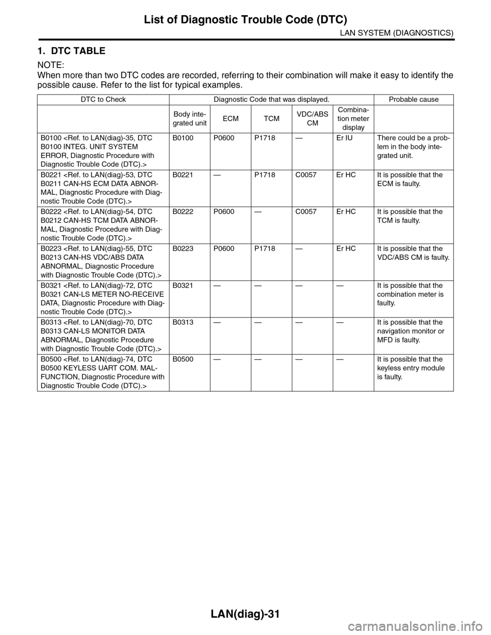
1. DTC TABLE
NOTE:
When more than two DTC codes are recorded, referring to their combination will make it easy to identify the
possible cause. Refer to the list for typical examples.
DTC to Check Diagnostic Code that was displayed. Probable cause
Body inte-
grated unitECM TCMVDC/ABS
CM
Combina-
tion meter
display
B0100
ERROR, Diagnostic Procedure with
Diagnostic Trouble Code (DTC).>
B0100 P0600 P1718 — Er IU There could be a prob-
lem in the body inte-
grated unit.
B0221
MAL, Diagnostic Procedure with Diag-
nostic Trouble Code (DTC).>
B0221 — P1718 C0057 Er HC It is possible that the
ECM is faulty.
B0222
MAL, Diagnostic Procedure with Diag-
nostic Trouble Code (DTC).>
B0222 P0600 — C0057 Er HC It is possible that the
TCM is faulty.
B0223
ABNORMAL, Diagnostic Procedure
with Diagnostic Trouble Code (DTC).>
B0223 P0600 P1718 — Er HC It is possible that the
VDC/ABS CM is faulty.
B0321
DATA, Diagnostic Procedure with Diag-
nostic Trouble Code (DTC).>
B0321 — — — — It is possible that the
combination meter is
faulty.
B0313
ABNORMAL, Diagnostic Procedure
with Diagnostic Trouble Code (DTC).>
B0313 — — — — It is possible that the
navigation monitor or
MFD is faulty.
B0500
FUNCTION, Diagnostic Procedure with
Diagnostic Trouble Code (DTC).>
B0500 — — — — It is possible that the
keyless entry module
is faulty.