ac 25 procedure SUBARU TRIBECA 2009 1.G Service Workshop Manual
[x] Cancel search | Manufacturer: SUBARU, Model Year: 2009, Model line: TRIBECA, Model: SUBARU TRIBECA 2009 1.GPages: 2453, PDF Size: 46.32 MB
Page 1130 of 2453
CO(H6DO)-11
Engine Coolant
COOLING
11) Wait for one minute after the engine stops,
open the radiator cap. If the engine coolant level
drops, add engine coolant into radiator up to the fill-
er neck position.
12) Perform the procedures 10) and 11) again.
13) Attach the radiator cap and reservoir tank cap
properly.
14) Start the engine and operate the heater at max-
imum hot position and the blower speed setting to
“LO.”
15) Run the engine at 2,000 rpm or less until radia-
tor fan starts and stops.
NOTE:
•Be careful with the engine coolant temperature
gauge to prevent overheating.
•If the radiator hose becomes harden with the
pressure of engine coolant, air bleeding operation
seems to be almost completed.
16) Stop the engine and wait until the engine cool-
ant temperature lowers to 30°C (86°F).
17) Open the radiator cap. If the engine coolant lev-
el drops, add engine coolant into radiator up to the
filler neck position and reservoir tank to the “FULL”
level.
18) Attach the radiator cap and reservoir tank cap
properly.
19) Set the heater setting to maximum hot position
and the blower speed setting to “LO” and start the
engine. Perform racing at less than 3,000 rpm. If
the flowing sound is heard at this time, perform the
procedures from 15) again.
B: INSPECTION
1. RELATIONSHIP OF SUBARU COOLANT
CONCENTRATION AND FREEZING TEM-
PERATURE
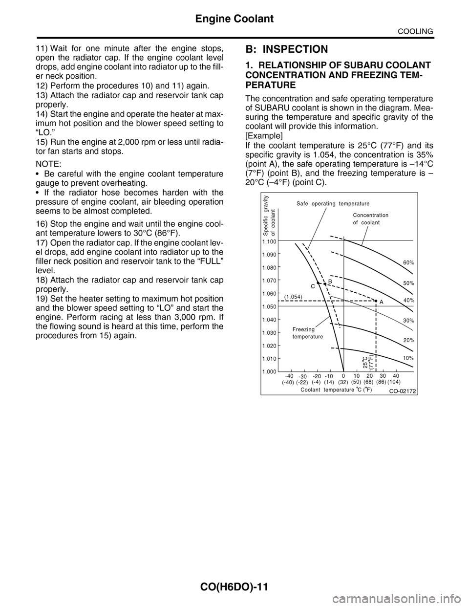
The concentration and safe operating temperature
of SUBARU coolant is shown in the diagram. Mea-
suring the temperature and specific gravity of the
coolant will provide this information.
[Example]
If the coolant temperature is 25°C (77°F) and its
specific gravity is 1.054, the concentration is 35%
(point A), the safe operating temperature is –14°C
(7°F) (point B), and the freezing temperature is –
20°C (–4°F) (point C).
CO-02172
60%
(1.054)
1.000
1.010
1.020
1.030
1.040
1.050
1.060
1.070
1.080
1.090
1.100
Safe operating temperature
Freezingtemperature
Concentrationof coolant
Specific gravityof coolant
Coolant temperature
B
A
C
-40(-40) (-22)(-4)(14)(32)(50) (68) (86)
( F)
(104)-30-20 -10010203040
(77 F)
50%
40%
30%
20%
25 C
10%
C
Page 1131 of 2453
CO(H6DO)-12
Engine Coolant
COOLING
2. PROCEDURE TO ADJUST THE CON-
CENTRATION OF THE COOLANT
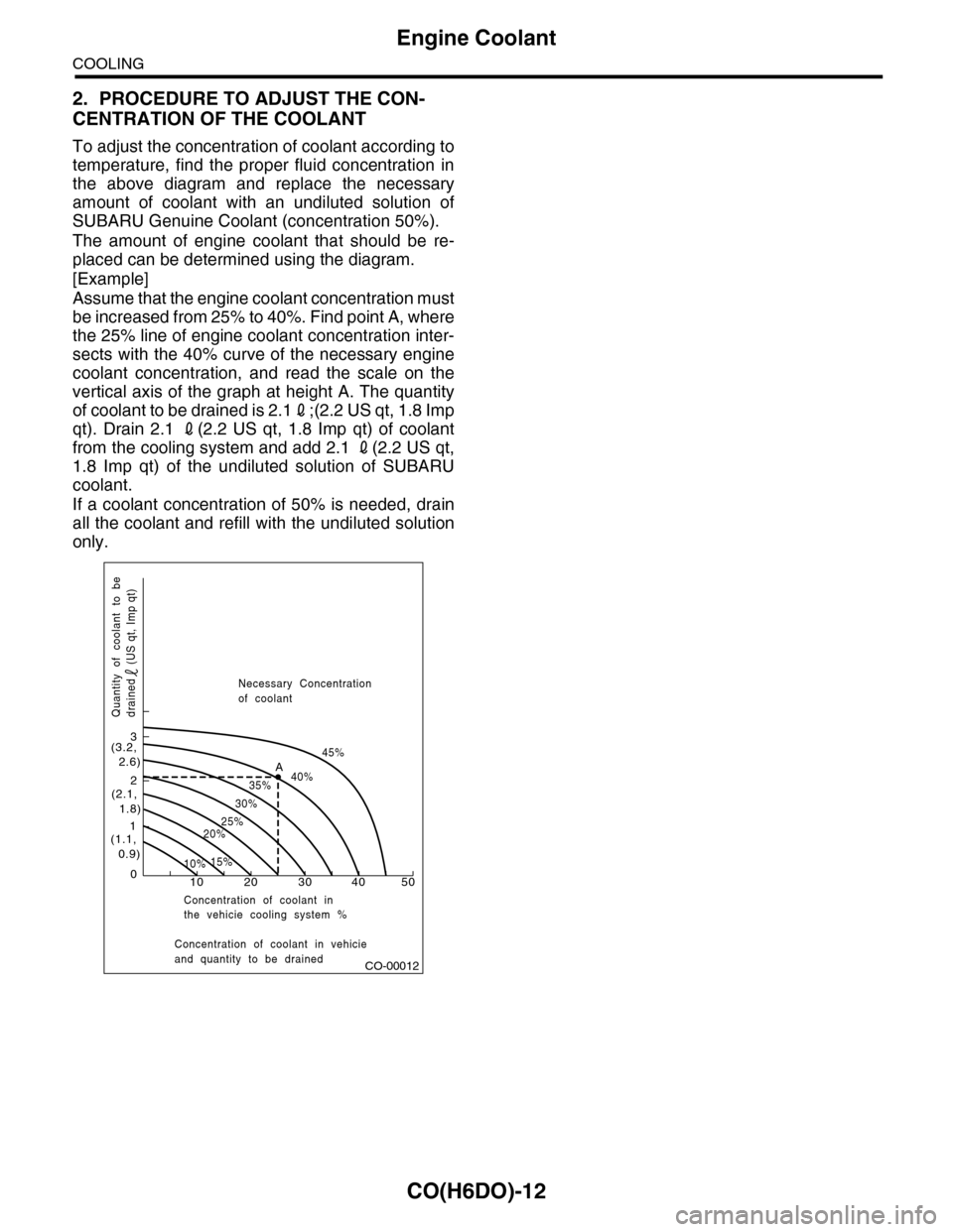
To adjust the concentration of coolant according to
temperature, find the proper fluid concentration in
the above diagram and replace the necessary
amount of coolant with an undiluted solution of
SUBARU Genuine Coolant (concentration 50%).
The amount of engine coolant that should be re-
placed can be determined using the diagram.
[Example]
Assume that the engine coolant concentration must
be increased from 25% to 40%. Find point A, where
the 25% line of engine coolant concentration inter-
sects with the 40% curve of the necessary engine
coolant concentration, and read the scale on the
vertical axis of the graph at height A. The quantity
of coolant to be drained is 2.12;(2.2 US qt, 1.8 Imp
qt). Drain 2.1 2(2.2 US qt, 1.8 Imp qt) of coolant
from the cooling system and add 2.1 2(2.2 US qt,
1.8 Imp qt) of the undiluted solution of SUBARU
coolant.
If a coolant concentration of 50% is needed, drain
all the coolant and refill with the undiluted solution
only.
CO-00012
100
1
2
3
(1.1, 0.9)
(2.1, 1.8)
(3.2, 2.6)
10%15%
25%20%
30%
35%40%
45%A
20 30 40 50
Concentration of coolant in vehicieand quantity to be drained
Quantity of coolant to bedrained (US qt, Imp qt)
Necessary Concentrationof coolant
Concentration of coolant inthe vehicie cooling system %
Page 1149 of 2453
CO(H6DO)-30
Engine Cooling System Trouble in General
COOLING
12.Engine Cooling System Trouble in General
A: INSPECTION
Tr o u b l e P o s s i b l e c a u s e C o r r e c t i v e a c t i o n
Overheating
a. Insufficient engine coolantReplenish engine coolant, inspect for leakage, and
repair it if necessary.
b. De fe c ti ve t he r mo st a t Rep la c e.
c. Malfunction of water pump Replace.
d. Clogged engine coolant passage Clean.
e. Improper ignition timing
Inspect and repair ignition control system.
Procedure.>
f. Clogged or leaking radiator Clean, repair or replace.
g. Improper engine oil in engine coolant Replace engine coolant.
h. Air/fuel mixture ratio too lean
Inspect and repair the fuel injection system.
Procedure.>
i. Excessive back pressure in exhaust system Clean or replace.
j. Insufficient clearance between piston and cylinder Adjust or replace.
k. Slipping clutch Correct or replace.
l. Dragging brake Adjust.
m. Faulty transmission gear oil Replace.
n. Malfunction of radiator fanInspect the radiator fan relay, engine coolant tempera-
ture sensor or fan motor and replace them.
Over-coolinga. Ambient temperature extremely low Partly cover radiator front area.
b. De fe c ti ve t he r mo st a t Rep la c e.
Engine coolant
leaks
a. Loosened or damaged connecting units on hoses Correct or replace.
b. L ea k ag e f r o m wat e r pu mp Rep la c e.
c. Leakage from water pipe Correct or replace.
d. Leakage around cylinder head gasket Retighten cylinder head bolts or replace gasket.
e. Damaged or cracked cylinder head and crankcase Correct or replace.
f. Damaged or cracked ther mostat case Correct or replace.
g. Leakage from radiator Correct or replace.
Strange noise
a. Defective drive belt Replace.
b. De fe c ti ve ra di a t or fan Rep la c e.
c. Defective water pump bearing Replace water pump.
d. Defective water pump mechanical seal Replace water pump.
Page 1151 of 2453
EC(H6DO)-3
Front Catalytic Converter
EMISSION CONTROL (AUX. EMISSION CONTROL DEVICES)
2. Front Catalytic Converter
A: REMOVAL
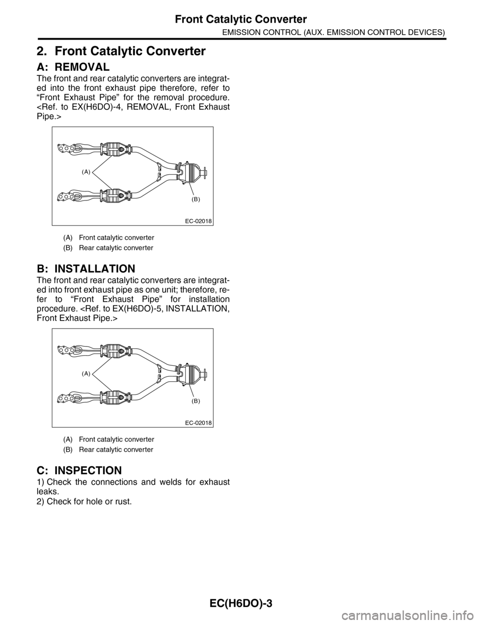
The front and rear catalytic converters are integrat-
ed into the front exhaust pipe therefore, refer to
“Front Exhaust Pipe” for the removal procedure.
B: INSTALLATION
The front and rear catalytic converters are integrat-
ed into front exhaust pipe as one unit; therefore, re-
fer to “Front Exhaust Pipe” for installation
procedure.
C: INSPECTION
1) Check the connections and welds for exhaust
leaks.
2) Check for hole or rust.
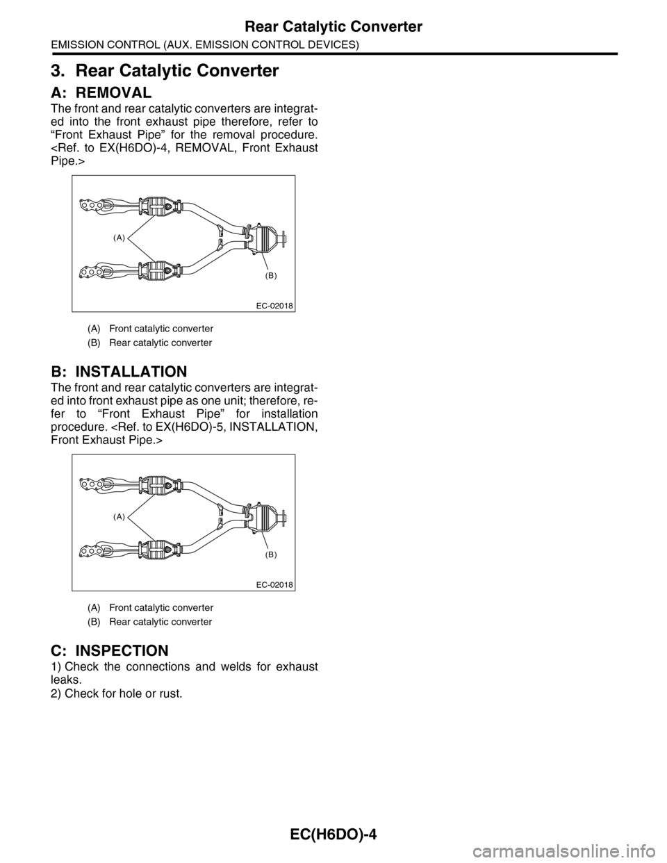
(A) Front catalytic converter
(B) Rear catalytic converter
(A) Front catalytic converter
(B) Rear catalytic converter
(A)
(B)
EC-02018
(A)
(B)
EC-02018
Page 1152 of 2453
EC(H6DO)-4
Rear Catalytic Converter
EMISSION CONTROL (AUX. EMISSION CONTROL DEVICES)
3. Rear Catalytic Converter
A: REMOVAL
The front and rear catalytic converters are integrat-
ed into the front exhaust pipe therefore, refer to
“Front Exhaust Pipe” for the removal procedure.
B: INSTALLATION
The front and rear catalytic converters are integrat-
ed into front exhaust pipe as one unit; therefore, re-
fer to “Front Exhaust Pipe” for installation
procedure.
C: INSPECTION
1) Check the connections and welds for exhaust
leaks.
2) Check for hole or rust.
(A) Front catalytic converter
(B) Rear catalytic converter
(A) Front catalytic converter
(B) Rear catalytic converter
(A)
(B)
EC-02018
(A)
(B)
EC-02018
Page 1155 of 2453
EC(H6DO)-7
Fuel Level Sensor
EMISSION CONTROL (AUX. EMISSION CONTROL DEVICES)
6. Fuel Level Sensor
A: REMOVAL
For removal procedure, refer to “FU(H6DO)” sec-
tion.
B: INSTALLATION
For installation procedure, refer to “FU(H6DO)”
section.
Page 1156 of 2453
EC(H6DO)-8
Fuel Temperature Sensor
EMISSION CONTROL (AUX. EMISSION CONTROL DEVICES)
7. Fuel Temperature Sensor
A: REMOVAL
The fuel temperature sensor and fuel level sensor
are integrated into one unit; therefore, refer to “Fuel
Level Sensor” for removal procedure.
B: INSTALLATION
The fuel temperature sensor and fuel level sensor
are integrated into one unit; therefore, refer to “Fuel
Level Sensor” for installation procedure.
sor.>
Page 1157 of 2453
EC(H6DO)-9
Fuel Sub Level Sensor
EMISSION CONTROL (AUX. EMISSION CONTROL DEVICES)
8. Fuel Sub Level Sensor
A: REMOVAL
For removal procedure, refer to “FU(H6DO)” sec-
tion.
B: INSTALLATION
For installation procedure, refer to “FU(H6DO)”
section.
Page 1163 of 2453
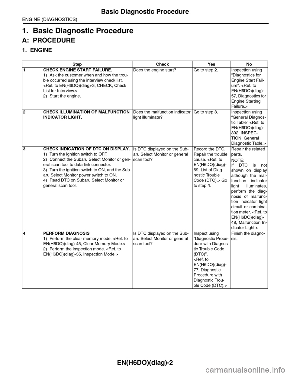
EN(H6DO)(diag)-2
Basic Diagnostic Procedure
ENGINE (DIAGNOSTICS)
1. Basic Diagnostic Procedure
A: PROCEDURE
1. ENGINE
Step Check Yes No
1CHECK ENGINE START FAILURE.
1) Ask the customer when and how the trou-
ble occurred using the interview check list.
2) Start the engine.
Does the engine start? Go to step 2.Inspection using
“Diagnostics for
Engine Start Fail-
ure”.
57, Diagnostics for
Engine Starting
Fai lu r e.>
2CHECK ILLUMINATION OF MALFUNCTION
INDICATOR LIGHT.
Does the malfunction indicator
light illuminate?
Go to step 3.Inspection using
“General Diagnos-
tic Table”
392, INSPEC-
TION, General
Diagnostic Table.>
3CHECK INDICATION OF DTC ON DISPLAY.
1) Turn the ignition switch to OFF.
2) Connect the Subaru Select Monitor or gen-
eral scan tool to data link connector.
3) Turn the ignition switch to ON, and the Sub-
aru Select Monitor power switch to ON.
4) Read DTC on Subaru Select Monitor or
general scan tool.
Is DTC displayed on the Sub-
aru Select Monitor or general
scan tool?
Record the DTC.
Repair the trouble
cause.
69, List of Diag-
nostic Trouble
Code (DTC).> Go
to step 4.
Repair the related
parts.
NOTE:
If DTC is not
shown on display
although the mal-
function indicator
light illuminates,
perform the diag-
nosis of malfunc-
tion indicator light
circuit or combina-
tion meter.
48, Malfunction In-
dicator Light.>
4PERFORM DIAGNOSIS
1) Perform the clear memory mode.
2) Perform the inspection mode.
Is DTC displayed on the Sub-
aru Select Monitor or general
scan tool?
Inspect using
“Diagnostic Proce-
dure with Diagnos-
tic Trouble Code
(DTC)”.
77, Diagnostic
Procedure with
Diagnostic Trou-
ble Code (DTC).>
Finish the diagno-
sis.
Page 1166 of 2453
EN(H6DO)(diag)-5
General Description
ENGINE (DIAGNOSTICS)
3. General Description
A: CAUTION
1) Airbag system wiring harness is routed near the
ECM, main relay and fuel pump relay.
CAUTION:
•All airbag system wiring harnesses and con-
nectors are colored yellow. Do not use electri-
cal test equipment on these circuits.
•Be careful not to damage the airbag system
wiring harness when servicing the ECM, TCM,
main relay and fuel pump relay.
2) Never connect the battery in reverse polarity.
•The ECM will be destroyed instantly.
•The fuel injector and other parts will be dam-
aged.
3) Do not disconnect the battery terminals while the
engine is running.
A large counter electromotive force will be generat-
ed in the generator, and this voltage may damage
electronic parts such as ECM etc.
4) Before disconnecting the connectors of each
sensor and ECM, be sure to turn the ignition switch
to OFF. Perform the clear memory mode after con-
necting the connectors.
5) Poor contact has been identified as a primary
cause of this problem. Measure the voltage or re-
sistance of individual sensor or all electrical control
modules using a tapered pin with a diameter of less
than 0.64 mm (0.025 in). Do not insert the pin more
than 5 mm (0.20 in) into the part.
6) Remove the ECM from the located position after
disconnecting two cables on battery.
Otherwise, the ECM may be damaged.
CAUTION:
When replacing the ECM, be careful not to use
the wrong spec. ECM to avoid any damage on
the fuel injection system.
7) Connectors of each sensor in the engine com-
partment and the harness connectors on the en-
gine side and body side are all designed to be
waterproof. Even if the connectors are waterproof,
take care not to allow water to get into them when
washing the vehicle, or when servicing the vehicle
in rainy weather.
8) Use ECM mounting stud bolts as the grounding
point to chassis when measuring voltage and resis-
tance in the passenger compartment.
9) Use the engine ground terminal or engine as-
sembly as the grounding point to chassis when
measuring the voltage and resistance in engine
compartment.
10) Every MFI-related part is a precision part. Do
not drop them.
11) Observe the following cautions when installing
a radio in MFI equipped models.
CAUTION:
•The antenna must be kept as far apart as pos-
sible from control unit. (The ECM is located un-
der the steering column, inside of the
instrument panel lower trim panel.)
•The antenna feeder must be placed as far apart
as possible from the ECM and MFI harness.
•Carefully adjust the antenna for correct
matching.
•When mounting a large power type radio, pay
special attention to the three items mentioned
above.
•Incorrect installation of the radio may affect
the operation of ECM.
12) Release the pressure in the fuel system before
disconnecting the fuel hose. If engine starts during
this operation, run it until it stops.
13) For the model with ABS, the ABS warning light
may illuminate when performing driving test with
jacked-up or lifted-up condition, but this is not a
system malfunction. The reason for this is the
speed difference between the front and rear
wheels. After diagnosis of engine control system,
perform the ABS memory clear procedure of self-
diagnosis function.
B: INSPECTION
Before performing diagnostics, check the following
item which might affect engine problems.
1. BATTERY
1) Measure the battery voltage and specific gravity
of electrolyte.
Standard voltage: 12 V
Specific gravity: Above 1.260
2) Check the condition of the main and other fuses,
and harnesses and connectors. Also check for
proper grounding.
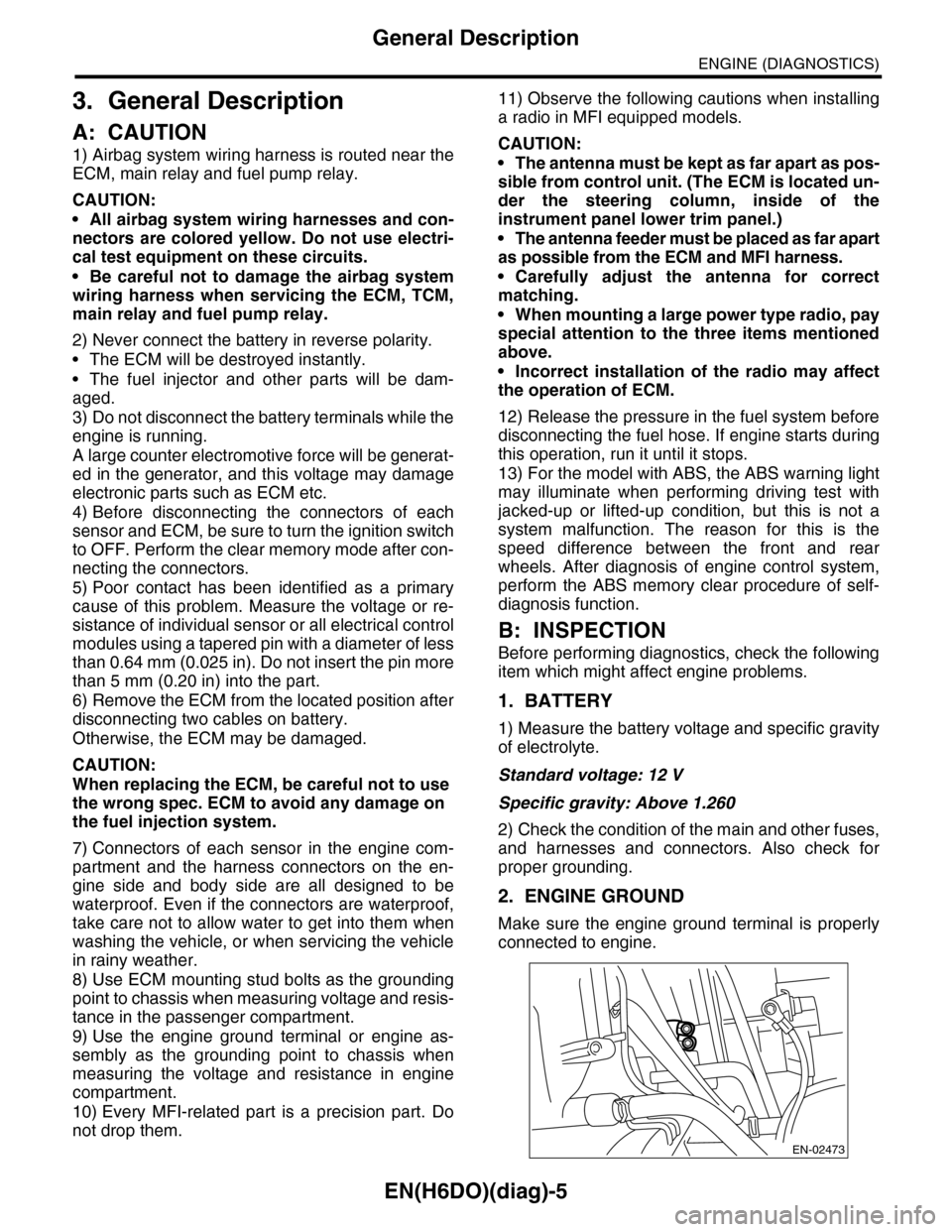
2. ENGINE GROUND
Make sure the engine ground terminal is properly
connected to engine.
EN-02473