ac 25 procedure SUBARU TRIBECA 2009 1.G Service Workshop Manual
[x] Cancel search | Manufacturer: SUBARU, Model Year: 2009, Model line: TRIBECA, Model: SUBARU TRIBECA 2009 1.GPages: 2453, PDF Size: 46.32 MB
Page 1627 of 2453
GD(H6DO)-15
Diagnostic Trouble Code (DTC) Detecting Criteria
GENERAL DESCRIPTION
F: DTC P0028 INTAKE VALVE CONTROL SOLENOID CIRCUIT RANGE/PER-
FORMANCE (BANK 2)
NOTE:
For diagnostic procedures, refer to DTC P0026.
Criteria.>
G: DTC P0030 HO2S HEATER CONTROL CIRCUIT (BANK 1 SENSOR 1)
1. OUTLINE OF DIAGNOSIS
Detect functional errors of the front oxygen (A/F) sensor heater.
Judge as NG when it is determined that the front oxygen (A/F) sensor impedance is large when looking at en-
gine status such as deceleration fuel cut.
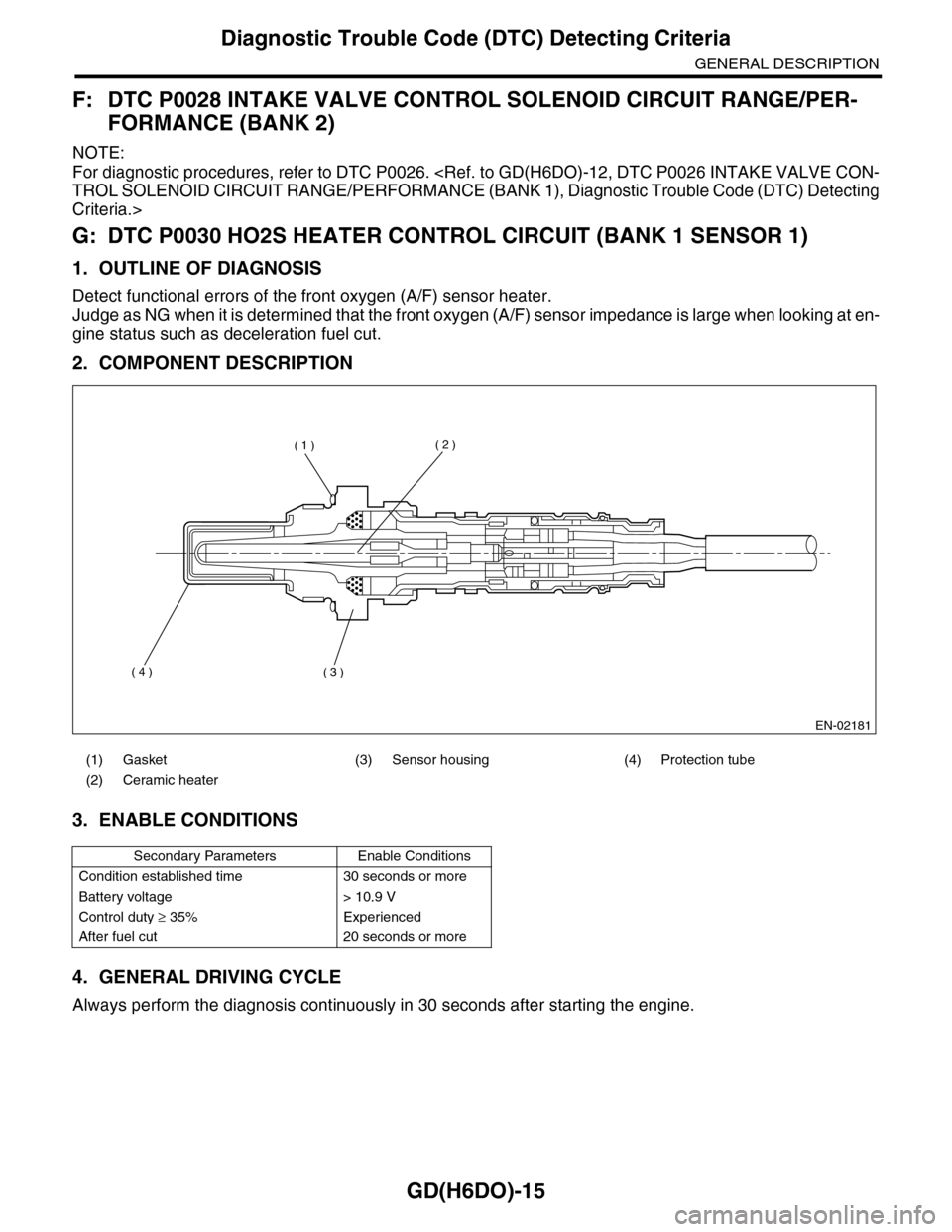
2. COMPONENT DESCRIPTION
3. ENABLE CONDITIONS
4. GENERAL DRIVING CYCLE
Always perform the diagnosis continuously in 30 seconds after starting the engine.
(1) Gasket (3) Sensor housing (4) Protection tube
(2) Ceramic heater
Secondary Parameters Enable Conditions
Condition established time 30 seconds or more
Battery voltage > 10.9 V
Control duty ≥ 35% Experienced
After fuel cut 20 seconds or more
EN-02181
( 1 )( 2 )
( 3 )( 4 )
Page 1637 of 2453
GD(H6DO)-25
Diagnostic Trouble Code (DTC) Detecting Criteria
GENERAL DESCRIPTION
L: DTC P0050 HO2S HEATER CONTROL CIRCUIT (BANK 2 SENSOR 1)
1. OUTLINE OF DIAGNOSIS
NOTE:
For the diagnostic procedure, refer to DTC P0030.
M: DTC P0051 HO2S HEATER CONTROL CIRCUIT LOW (BANK 2 SENSOR 1)
1. OUTLINE OF DIAGNOSIS
NOTE:
For the diagnostic procedure, refer to DTC P0031.
N: DTC P0052 HO2S HEATER CONTROL CIRCUIT HIGH (BANK 2 SENSOR 1)
1. OUTLINE OF DIAGNOSIS
NOTE:
For the diagnostic procedure, refer to DTC P0032.
O: DTC P0057 HO2S HEATER CONTROL CIRCUIT LOW (BANK 2 SENSOR 2)
1. OUTLINE OF DIAGNOSIS
NOTE:
For the diagnostic procedure, refer to DTC P0037.
P: DTC P0058 HO2S HEATER CONTROL CIRCUIT HIGH (BANK 2 SENSOR 2)
1. OUTLINE OF DIAGNOSIS
NOTE:
For the diagnostic procedure, refer to DTC P0038.
Page 1642 of 2453
GD(H6DO)-30
Diagnostic Trouble Code (DTC) Detecting Criteria
GENERAL DESCRIPTION
T: DTC P0082 INTAKE VALVE CONTROL CIRCUIT LOW (BANK 2)
1. OUTLINE OF DIAGNOSIS
NOTE:
For the diagnostic procedure, refer to DTC P0076.
U: DTC P0083 INTAKE VALVE CONTROL CIRCUIT HIGH (BANK 2)
1. OUTLINE OF DIAGNOSIS
NOTE:
For the diagnostic procedure, refer to DTC P0077.
Page 1686 of 2453
GD(H6DO)-74
Diagnostic Trouble Code (DTC) Detecting Criteria
GENERAL DESCRIPTION
AP:DTC P0138 O2 SENSOR CIRCUIT HIGH VOLTAGE (BANK 1 SENSOR 2)
1. OUTLINE OF DIAGNOSIS
NOTE:
For the diagnostic procedure, refer to DTC P0137.
Page 1693 of 2453
GD(H6DO)-81
Diagnostic Trouble Code (DTC) Detecting Criteria
GENERAL DESCRIPTION
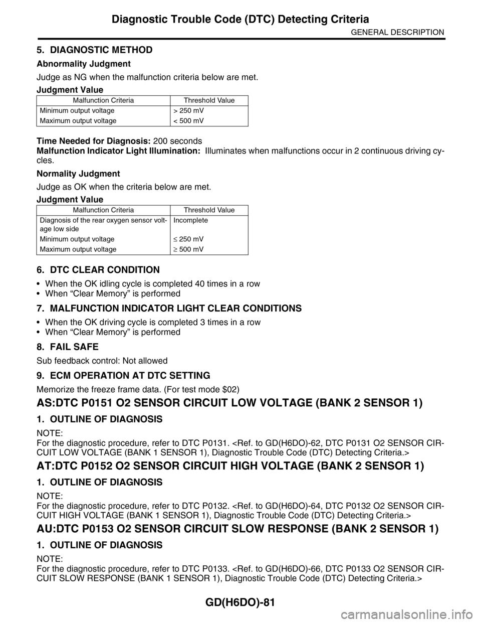
5. DIAGNOSTIC METHOD
Abnormality Judgment
Judge as NG when the malfunction criteria below are met.
Time Needed for Diagnosis: 200 seconds
Malfunction Indicator Light Illumination: Illuminates when malfunctions occur in 2 continuous driving cy-
cles.
Normality Judgment
Judge as OK when the criteria below are met.
6. DTC CLEAR CONDITION
•When the OK idling cycle is completed 40 times in a row
•When “Clear Memory” is performed
7. MALFUNCTION INDICATOR LIGHT CLEAR CONDITIONS
•When the OK driving cycle is completed 3 times in a row
•When “Clear Memory” is performed
8. FAIL SAFE
Sub feedback control: Not allowed
9. ECM OPERATION AT DTC SETTING
Memorize the freeze frame data. (For test mode $02)
AS:DTC P0151 O2 SENSOR CIRCUIT LOW VOLTAGE (BANK 2 SENSOR 1)
1. OUTLINE OF DIAGNOSIS
NOTE:
For the diagnostic procedure, refer to DTC P0131.
AT:DTC P0152 O2 SENSOR CIRCUIT HIGH VOLTAGE (BANK 2 SENSOR 1)
1. OUTLINE OF DIAGNOSIS
NOTE:
For the diagnostic procedure, refer to DTC P0132.
AU:DTC P0153 O2 SENSOR CIRCUIT SLOW RESPONSE (BANK 2 SENSOR 1)
1. OUTLINE OF DIAGNOSIS
NOTE:
For the diagnostic procedure, refer to DTC P0133.
Judgment Value
Malfunction Criteria Threshold Value
Minimum output voltage > 250 mV
Maximum output voltage < 500 mV
Judgment Value
Malfunction Criteria Threshold Value
Diagnosis of the rear oxygen sensor volt-
age low side
Incomplete
Minimum output voltage≤ 250 mV
Maximum output voltage≥ 500 mV
Page 1694 of 2453
GD(H6DO)-82
Diagnostic Trouble Code (DTC) Detecting Criteria
GENERAL DESCRIPTION
AV:DTC P0154 O2 SENSOR CIRCUIT NO ACTIVITY DETECTED (BANK 2 SEN-
SOR 1)
1. OUTLINE OF DIAGNOSIS
NOTE:
For the diagnostic procedure, refer to DTC P0134.
AW:DTC P0157 O2 SENSOR CIRCUIT LOW VOLTAGE (BANK 2 SENSOR 2)
1. OUTLINE OF DIAGNOSIS
NOTE:
For the diagnostic procedure, refer to DTC P0137.
AX:DTC P0158 O2 SENSOR CIRCUIT HIGH VOLTAGE (BANK 2 SENSOR 2)
1. OUTLINE OF DIAGNOSIS
NOTE:
For the diagnostic procedure, refer to DTC P0137.
AY:DTC P0159 O2 SENSOR CIRCUIT SLOW RESPONSE (BANK 2 SENSOR 2)
1. OUTLINE OF DIAGNOSIS
NOTE:
For the diagnostic procedure, refer to DTC P0139.
AZ:DTC P0160 O2 SENSOR CIRCUIT NO ACTIVITY DETECTED (BANK 2 SEN-
SOR 2)
1. OUTLINE OF DIAGNOSIS
NOTE:
For the diagnostic procedure, refer to DTC P0140.
Page 1698 of 2453
GD(H6DO)-86
Diagnostic Trouble Code (DTC) Detecting Criteria
GENERAL DESCRIPTION
6. MALFUNCTION INDICATOR LIGHT CLEAR CONDITIONS
•When similar driving conditions are repeated 3 times and the result is OK.
•When “Clear Memory” is performed
7. FAIL SAFE
Purge control solenoid valve control: Not allowed to purge.
8. ECM OPERATION AT DTC SETTING
Memorize the freeze frame data. (For test mode $02)
BC:DTC P0174 SYSTEM TOO LEAN (BANK 2)
1. OUTLINE OF DIAGNOSIS
NOTE:
For the diagnostic procedure, refer to DTC P0171.
BD:DTC P0175 SYSTEM TOO RICH (BANK 2)
1. OUTLINE OF DIAGNOSIS
NOTE:
For the diagnostic procedure, refer to DTC P0172.
Page 1721 of 2453
GD(H6DO)-109
Diagnostic Trouble Code (DTC) Detecting Criteria
GENERAL DESCRIPTION
BO:DTC P0302 CYLINDER 2 MISFIRE DETECTED
1. OUTLINE OF DIAGNOSIS
NOTE:
For the diagnostic procedure, refer to DTC P0301.
BP:DTC P0303 CYLINDER 3 MISFIRE DETECTED
1. OUTLINE OF DIAGNOSIS
NOTE:
For the diagnostic procedure, refer to DTC P0301.
BQ:DTC P0304 CYLINDER 4 MISFIRE DETECTED
1. OUTLINE OF DIAGNOSIS
NOTE:
For the diagnostic procedure, refer to DTC P0301.
BR:DTC P0305 CYLINDER 5 MISFIRE DETECTED
1. OUTLINE OF DIAGNOSIS
NOTE:
For the diagnostic procedure, refer to DTC P0301.
BS:DTC P0306 CYLINDER 6 MISFIRE DETECTED
1. OUTLINE OF DIAGNOSIS
NOTE:
For the diagnostic procedure, refer to DTC P0301.
Page 1725 of 2453
GD(H6DO)-113
Diagnostic Trouble Code (DTC) Detecting Criteria
GENERAL DESCRIPTION
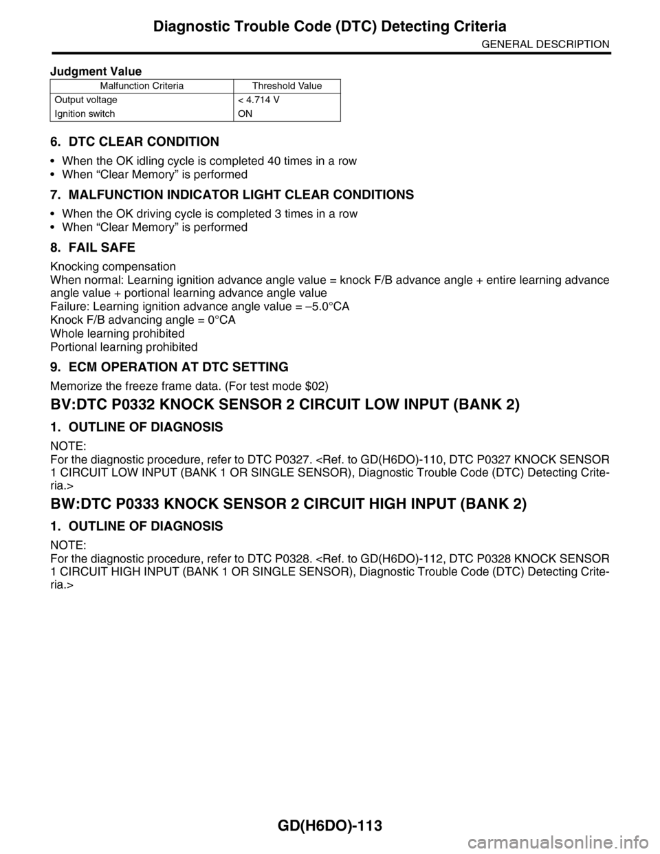
6. DTC CLEAR CONDITION
•When the OK idling cycle is completed 40 times in a row
•When “Clear Memory” is performed
7. MALFUNCTION INDICATOR LIGHT CLEAR CONDITIONS
•When the OK driving cycle is completed 3 times in a row
•When “Clear Memory” is performed
8. FAIL SAFE
Knocking compensation
When normal: Learning ignition advance angle value = knock F/B advance angle + entire learning advance
angle value + portional learning advance angle value
Failure: Learning ignition advance angle value = –5.0°CA
Knock F/B advancing angle = 0°CA
Whole learning prohibited
Portional learning prohibited
9. ECM OPERATION AT DTC SETTING
Memorize the freeze frame data. (For test mode $02)
BV:DTC P0332 KNOCK SENSOR 2 CIRCUIT LOW INPUT (BANK 2)
1. OUTLINE OF DIAGNOSIS
NOTE:
For the diagnostic procedure, refer to DTC P0327.
ria.>
BW:DTC P0333 KNOCK SENSOR 2 CIRCUIT HIGH INPUT (BANK 2)
1. OUTLINE OF DIAGNOSIS
NOTE:
For the diagnostic procedure, refer to DTC P0328.
ria.>
Judgment Value
Malfunction Criteria Threshold Value
Output voltage < 4.714 V
Ignition switch ON
Page 1732 of 2453
GD(H6DO)-120
Diagnostic Trouble Code (DTC) Detecting Criteria
GENERAL DESCRIPTION
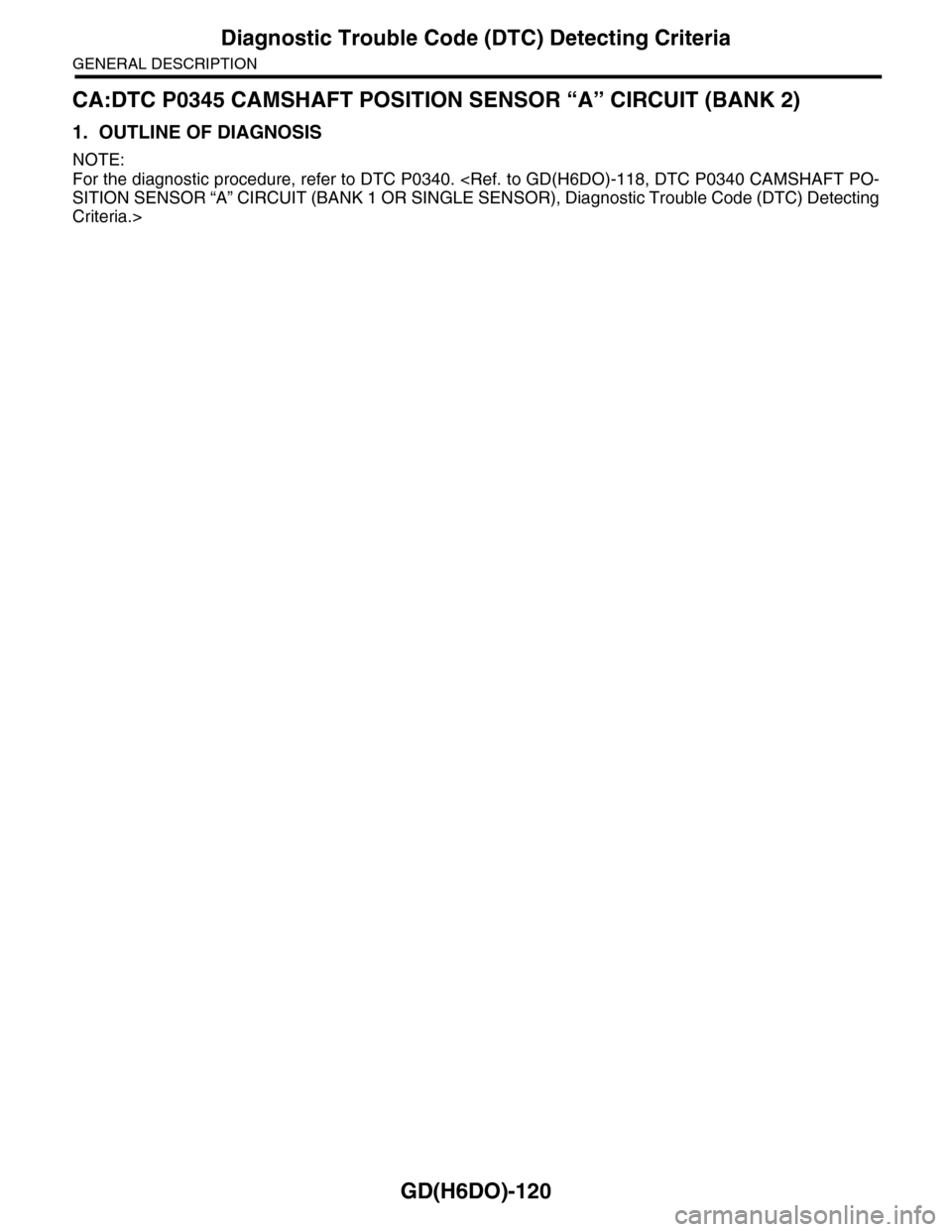
CA:DTC P0345 CAMSHAFT POSITION SENSOR “A” CIRCUIT (BANK 2)
1. OUTLINE OF DIAGNOSIS
NOTE:
For the diagnostic procedure, refer to DTC P0340.
Criteria.>