ac 25 procedure SUBARU TRIBECA 2009 1.G Service Workshop Manual
[x] Cancel search | Manufacturer: SUBARU, Model Year: 2009, Model line: TRIBECA, Model: SUBARU TRIBECA 2009 1.GPages: 2453, PDF Size: 46.32 MB
Page 1798 of 2453
GD(H6DO)-186
Diagnostic Trouble Code (DTC) Detecting Criteria
GENERAL DESCRIPTION
DH:DTC P1154 O2 SENSOR CIRCUIT RANGE/PERFORMANCE (LOW) (BANK 2
SENSOR 1)
1. OUTLINE OF DIAGNOSIS
NOTE:
For the diagnostic procedure, refer to DTC P1152.
Criteria.>
DI: DTC P1155 O2 SENSOR CIRCUIT RANGE/PERFORMANCE (HIGH) (BANK 2
SENSOR 1)
1. OUTLINE OF DIAGNOSIS
NOTE:
For the diagnostic procedure, refer to DTC P1153.
Criteria.>
Page 1808 of 2453
GD(H6DO)-196
Diagnostic Trouble Code (DTC) Detecting Criteria
GENERAL DESCRIPTION
DW:DTC P2092 OCV SOLENOID VALVE SIGNAL A CIRCUIT OPEN (BANK 2)
1. OUTLINE OF DIAGNOSIS
NOTE:
For the detection procedure, refer to DTC P2088.
DX:DTC P2093 OCV SOLENOID VALVE SIGNAL A CIRCUIT SHORT (BANK 2)
1. OUTLINE OF DIAGNOSIS
NOTE:
For the detection procedure, refer to DTC P2089.
Page 1812 of 2453
GD(H6DO)-200
Diagnostic Trouble Code (DTC) Detecting Criteria
GENERAL DESCRIPTION
Time Needed for Diagnosis: 5 seconds
Malfunction Indicator Light Illumination: Illuminates when malfunctions occur in 2 continuous driving cy-
cles.
6. DTC CLEAR CONDITION
•When the OK idling cycle is completed 40 times in a row
•When “Clear Memory” is performed
7. MALFUNCTION INDICATOR LIGHT CLEAR CONDITIONS
•When similar driving conditions are repeated 3 times and the result is OK.
•When “Clear Memory” is performed
8. FAIL SAFE
None
9. ECM OPERATION AT DTC SETTING
Memorize the freeze frame data. (For test mode $02)
EA:DTC P2098 POST CATALYST FUEL TRIM SYSTEM TOO LEAN (BANK 2)
1. OUTLINE OF DIAGNOSIS
NOTE:
For the detection procedure, refer to DTC P2096.
EB:DTC P2099 POST CATALYST FUEL TRIM SYSTEM TOO RICH (BANK 2)
1. OUTLINE OF DIAGNOSIS
NOTE:
For the detection procedure, refer to DTC P2097.
Page 1842 of 2453
IG(H6DO)-7
Ignition Coil & Ignitor Assembly
IGNITION
3. Ignition Coil & Ignitor Assem-
bly
A: REMOVAL
Direct ignition type has been adopted. Refer to
“Spark Plug” for removal procedure.
B: INSTALLATION
Install in the reverse order of removal.
Tightening torque:
16 N·m (1.6 kgf-m, 11.7 ft-lb)
C: INSPECTION
For inspection procedure, refer to “Diagnostics for
Engine Starting Failure.”
for Engine Starting Failure.>
Page 1850 of 2453
IN(H6DO)-8
Resonator Chamber
INTAKE (INDUCTION)
6. Resonator Chamber
A: REMOVAL
The resonator chamber and air cleaner case are in-
tegrated into one unit; therefore, refer to “Air Clean-
er Case” for removal procedure.
B: INSTALLATION
The resonator chamber and air cleaner case are in-
tegrated into one unit; therefore, refer to “Air Clean-
er Case” for installation procedure.
C: INSPECTION
Check for cracks or loose connections.
Page 1859 of 2453
LU(H6DO)-10
Oil Pump Relief Valve
LUBRICATION
5. Oil Pump Relief Valve
A: REMOVAL
1. REAR CHAIN COVER SIDE
Oil pump relief valve is integrated into oil pump cov-
er as one unit; therefore, refer to “Oil Pump” for re-
moval procedure.
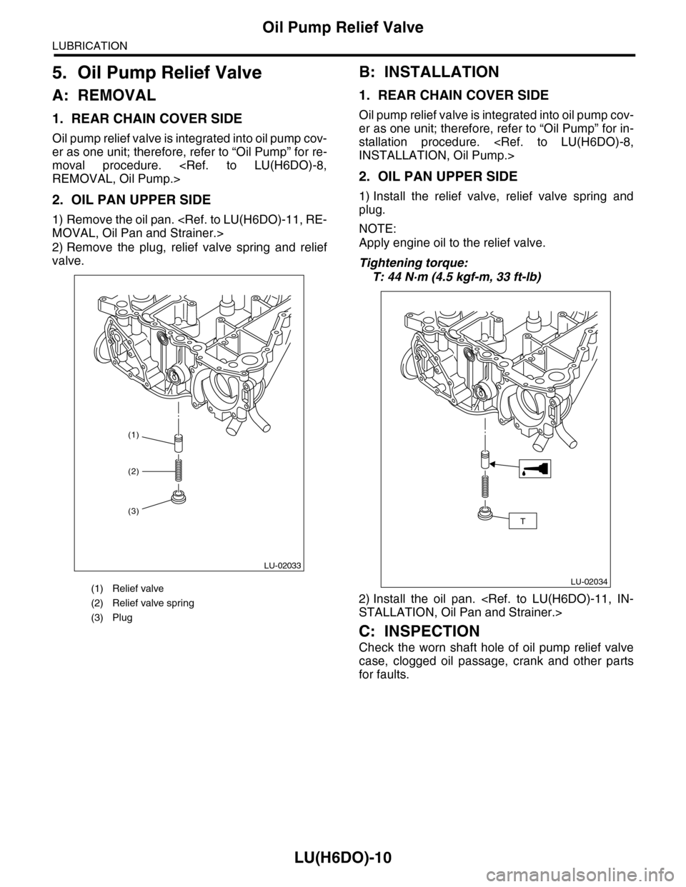
2. OIL PAN UPPER SIDE
1) Remove the oil pan.
2) Remove the plug, relief valve spring and relief
valve.
B: INSTALLATION
1. REAR CHAIN COVER SIDE
Oil pump relief valve is integrated into oil pump cov-
er as one unit; therefore, refer to “Oil Pump” for in-
stallation procedure.
2. OIL PAN UPPER SIDE
1) Install the relief valve, relief valve spring and
plug.
NOTE:
Apply engine oil to the relief valve.
Tightening torque:
T: 44 N·m (4.5 kgf-m, 33 ft-lb)
2) Install the oil pan.
C: INSPECTION
Check the worn shaft hole of oil pump relief valve
case, clogged oil passage, crank and other parts
for faults.
(1) Relief valve
(2) Relief valve spring
(3) Plug
(1)
LU-02033
(2)
(3)
LU-02034
T
Page 1886 of 2453
ME(H6DO)-20
General Description
MECHANICAL
2. GENERAL TOOL
E: PROCEDURE
It is possible to conduct the following service procedures with engine on vehicle, however, the procedures
described in this section are based on the condition that the engine is removed from vehicle.
•Camshaft
•Cylinder head
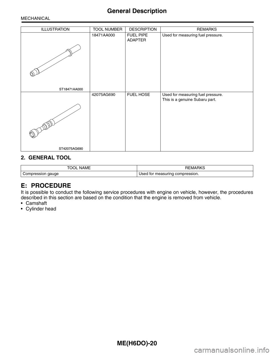
18471AA000 FUEL PIPE
ADAPTER
Used for measuring fuel pressure.
42075AG690 FUEL HOSE Used for measuring fuel pressure.
This is a genuine Subaru part.
TOOL NAME REMARKS
Compression gauge Used for measuring compression.
ILLUSTRATION TOOL NUMBER DESCRIPTION REMARKS
Page 1887 of 2453
ME(H6DO)-21
Compression
MECHANICAL
2. Compression
A: INSPECTION
CAUTION:
After warming-up, engine becomes very hot. Be
careful not to burn yourself during measure-
ment.
1) After warming-up the engine, turn the ignition
switch to OFF.
2) Make sure that the battery is fully charged.
3) Release the fuel pressure.
4) Remove all the spark plugs.
5) Check the starter motor for satisfactory perfor-
mance and operation.
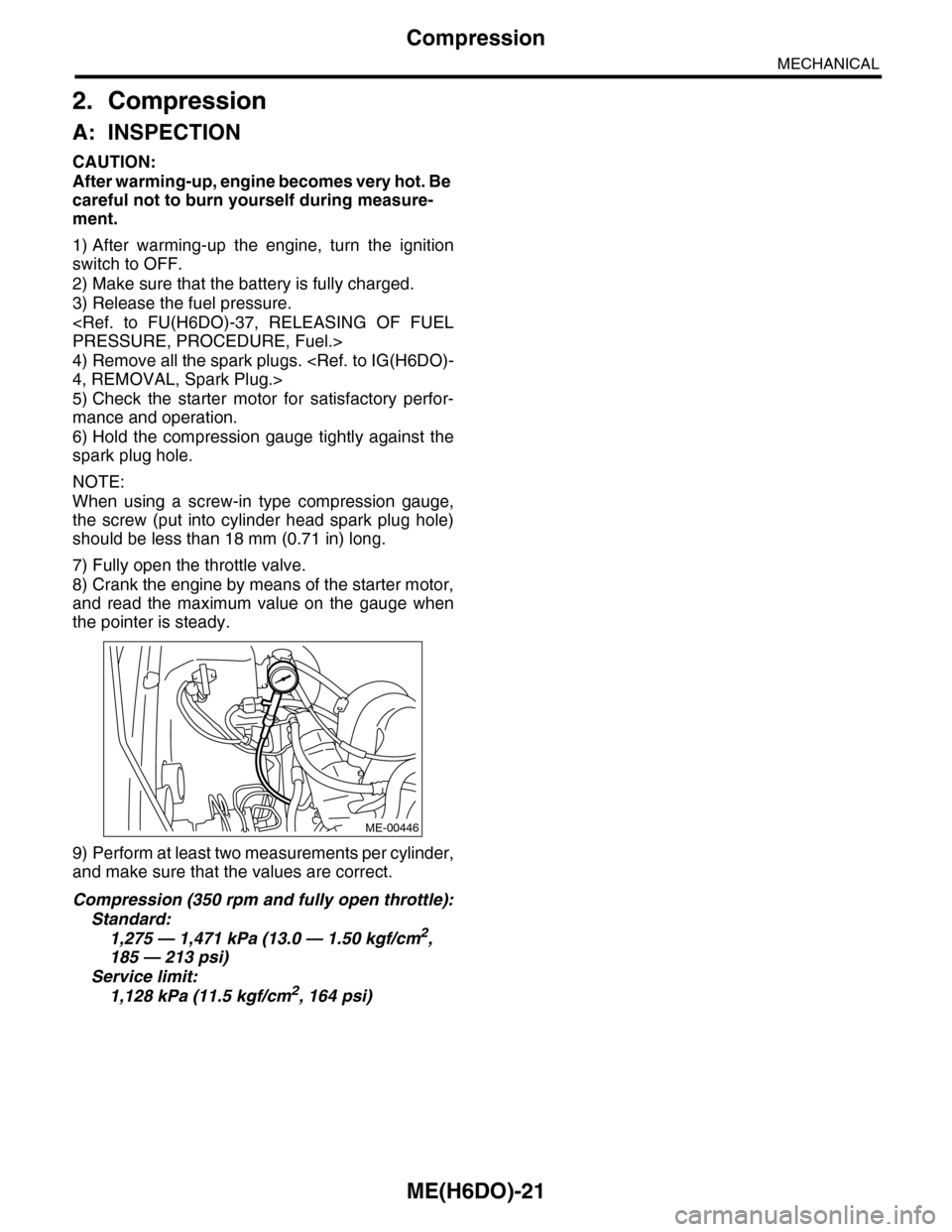
6) Hold the compression gauge tightly against the
spark plug hole.
NOTE:
When using a screw-in type compression gauge,
the screw (put into cylinder head spark plug hole)
should be less than 18 mm (0.71 in) long.
7) Fully open the throttle valve.
8) Crank the engine by means of the starter motor,
and read the maximum value on the gauge when
the pointer is steady.
9) Perform at least two measurements per cylinder,
and make sure that the values are correct.
Compression (350 rpm and fully open throttle):
Standard:
1,275 — 1,471 kPa (13.0 — 1.50 kgf/cm2,
185 — 213 psi)
Service limit:
1,128 kPa (11.5 kgf/cm2, 164 psi)
ME-00446
Page 1888 of 2453
ME(H6DO)-22
Idle Speed
MECHANICAL
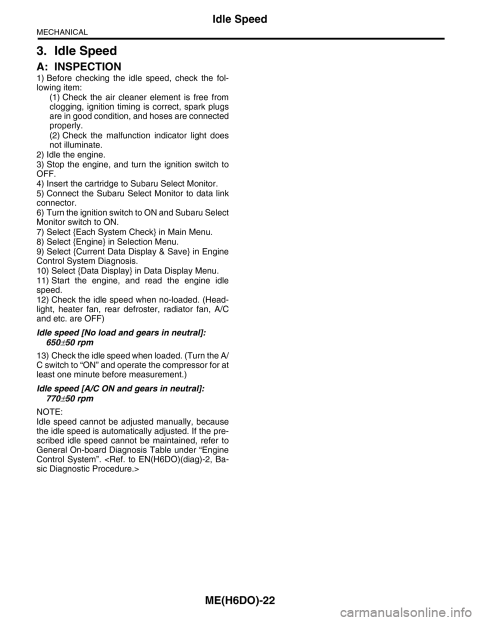
3. Idle Speed
A: INSPECTION
1) Before checking the idle speed, check the fol-
lowing item:
(1) Check the air cleaner element is free from
clogging, ignition timing is correct, spark plugs
are in good condition, and hoses are connected
properly.
(2) Check the malfunction indicator light does
not illuminate.
2) Idle the engine.
3) Stop the engine, and turn the ignition switch to
OFF.
4) Insert the cartridge to Subaru Select Monitor.
5) Connect the Subaru Select Monitor to data link
connector.
6) Turn the ignition switch to ON and Subaru Select
Monitor switch to ON.
7) Select {Each System Check} in Main Menu.
8) Select {Engine} in Selection Menu.
9) Select {Current Data Display & Save} in Engine
Control System Diagnosis.
10) Select {Data Display} in Data Display Menu.
11) Start the engine, and read the engine idle
speed.
12) Check the idle speed when no-loaded. (Head-
light, heater fan, rear defroster, radiator fan, A/C
and etc. are OFF)
Idle speed [No load and gears in neutral]:
650±50 rpm
13) Check the idle speed when loaded. (Turn the A/
C switch to “ON” and operate the compressor for at
least one minute before measurement.)
Idle speed [A/C ON and gears in neutral]:
770±50 rpm
NOTE:
Idle speed cannot be adjusted manually, because
the idle speed is automatically adjusted. If the pre-
scribed idle speed cannot be maintained, refer to
General On-board Diagnosis Table under “Engine
Control System”.
Page 1889 of 2453
ME(H6DO)-23
Ignition Timing
MECHANICAL
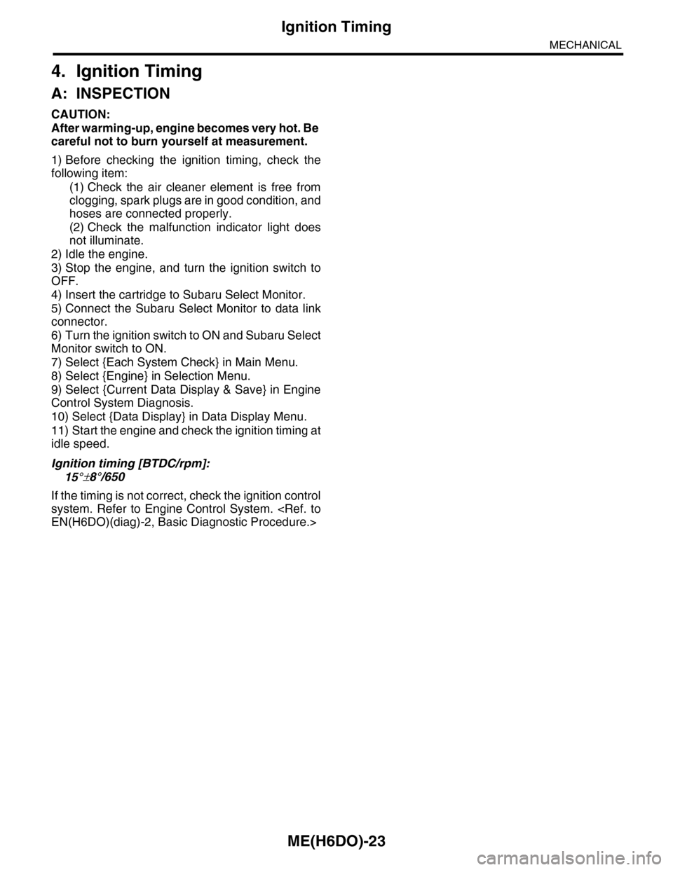
4. Ignition Timing
A: INSPECTION
CAUTION:
After warming-up, engine becomes very hot. Be
careful not to burn yourself at measurement.
1) Before checking the ignition timing, check the
following item:
(1) Check the air cleaner element is free from
clogging, spark plugs are in good condition, and
hoses are connected properly.
(2) Check the malfunction indicator light does
not illuminate.
2) Idle the engine.
3) Stop the engine, and turn the ignition switch to
OFF.
4) Insert the cartridge to Subaru Select Monitor.
5) Connect the Subaru Select Monitor to data link
connector.
6) Turn the ignition switch to ON and Subaru Select
Monitor switch to ON.
7) Select {Each System Check} in Main Menu.
8) Select {Engine} in Selection Menu.
9) Select {Current Data Display & Save} in Engine
Control System Diagnosis.
10) Select {Data Display} in Data Display Menu.
11) Start the engine and check the ignition timing at
idle speed.
Ignition timing [BTDC/rpm]:
15°±8°/650
If the timing is not correct, check the ignition control
system. Refer to Engine Control System.