ac 25 procedure SUBARU TRIBECA 2009 1.G Service Workshop Manual
[x] Cancel search | Manufacturer: SUBARU, Model Year: 2009, Model line: TRIBECA, Model: SUBARU TRIBECA 2009 1.GPages: 2453, PDF Size: 46.32 MB
Page 2015 of 2453
PM-32
Supplemental Restraint System
PERIODIC MAINTENANCE SERVICES
22.Supplemental Restraint System
A: INSPECTION
Check the airbag system in accordance with the result of the self-diagnosis.
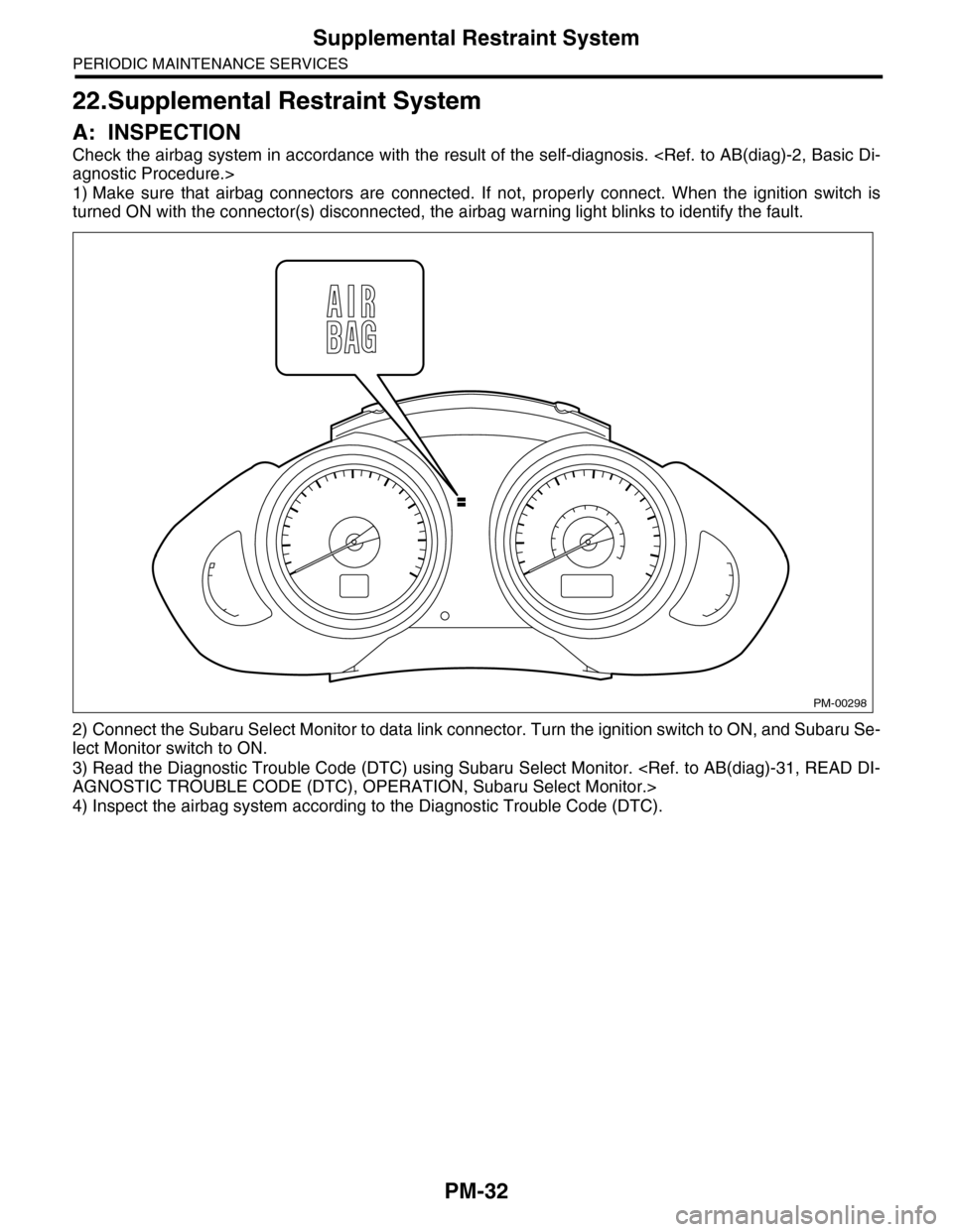
1) Make sure that airbag connectors are connected. If not, properly connect. When the ignition switch is
turned ON with the connector(s) disconnected, the airbag warning light blinks to identify the fault.
2) Connect the Subaru Select Monitor to data link connector. Turn the ignition switch to ON, and Subaru Se-
lect Monitor switch to ON.
3) Read the Diagnostic Trouble Code (DTC) using Subaru Select Monitor.
4) Inspect the airbag system according to the Diagnostic Trouble Code (DTC).
PM-00298
Page 2016 of 2453
PM-33
A/C Filter
PERIODIC MAINTENANCE SERVICES
23.A/C Filter
A: REPLACEMENT
For the A/C filter replacement procedures, refer to
the AC section.
Page 2046 of 2453
5AT-30
Stall Test
AUTOMATIC TRANSMISSION
5. Stall Test
A: INSPECTION
NOTE:
The stall test is extremely important in diagnosing
the condition of an automatic transmission and en-
gine. It should be conducted to measure the engine
stall speeds in “R” and “2nd of manual mode”.
Purposes of the stall test:
•Operational check of the automatic transmission
clutch
•Operational check of the torque converter clutch
•Engine performance check
1) Check that the throttle valve fully opens.
2) Check that the engine oil level is correct.
3) Check that the coolant level is correct.
4) Check that the ATF level is correct.
5) Check that the differential gear oil level is cor-
rect.
6) Raise the ATF temperature to 70 to 80°C (158 to
176°F) by driving a distance of 5 to 10 km (3 to 6
miles). Confirm the ATF temperature on Subaru
Select Monitor.
tor.>
7) Place the wheel chocks at the front and rear of
all wheels and apply the parking brake.
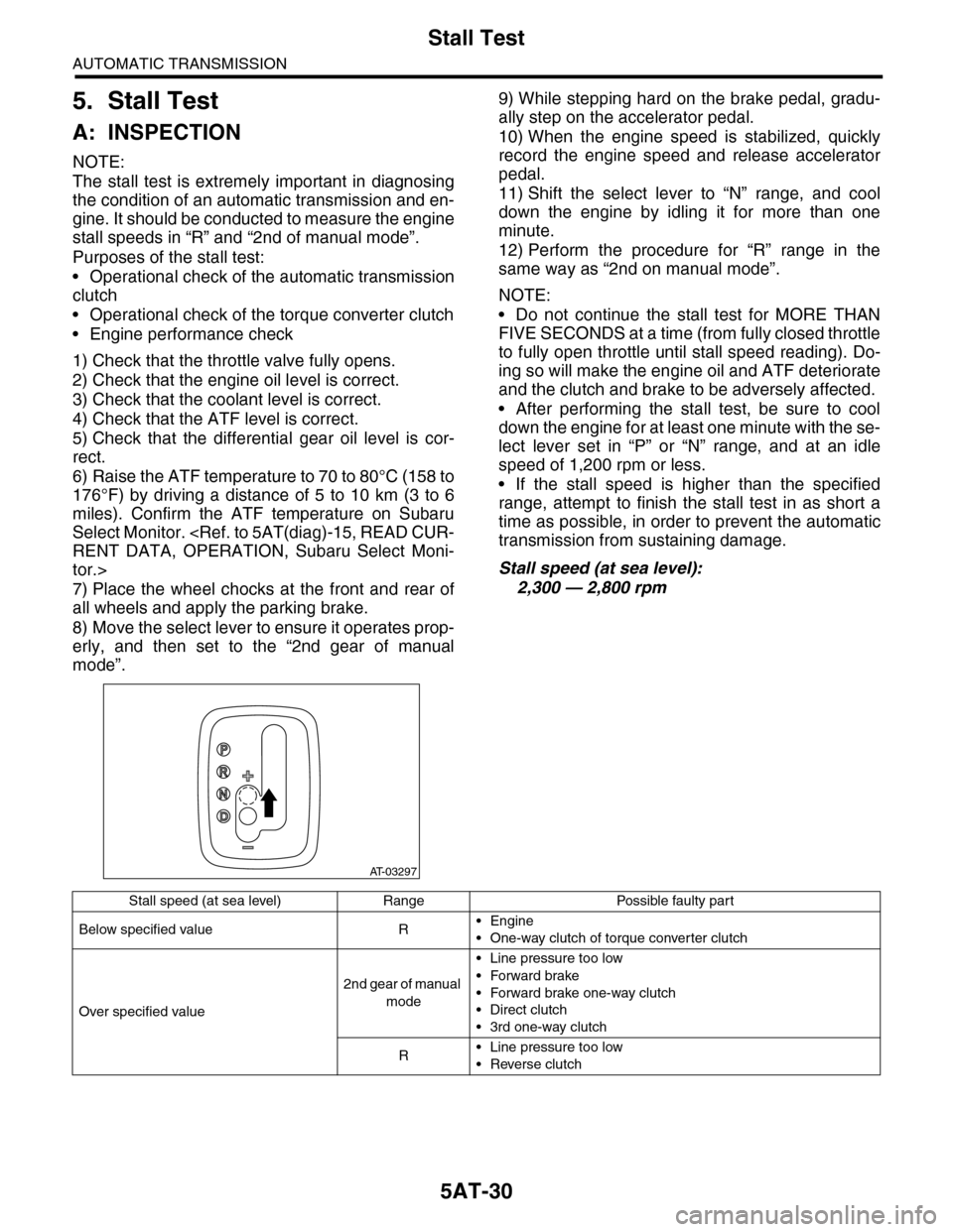
8) Move the select lever to ensure it operates prop-
erly, and then set to the “2nd gear of manual
mode”.
9) While stepping hard on the brake pedal, gradu-
ally step on the accelerator pedal.
10) When the engine speed is stabilized, quickly
record the engine speed and release accelerator
pedal.
11) Shift the select lever to “N” range, and cool
down the engine by idling it for more than one
minute.
12) Perform the procedure for “R” range in the
same way as “2nd on manual mode”.
NOTE:
•Do not continue the stall test for MORE THAN
FIVE SECONDS at a time (from fully closed throttle
to fully open throttle until stall speed reading). Do-
ing so will make the engine oil and ATF deteriorate
and the clutch and brake to be adversely affected.
•After performing the stall test, be sure to cool
down the engine for at least one minute with the se-
lect lever set in “P” or “N” range, and at an idle
speed of 1,200 rpm or less.
•If the stall speed is higher than the specified
range, attempt to finish the stall test in as short a
time as possible, in order to prevent the automatic
transmission from sustaining damage.
Stall speed (at sea level):
2,300 — 2,800 rpm
AT-03297
Stall speed (at sea level) Range Possible faulty part
Below specified value R•Engine
•One-way clutch of torque converter clutch
Over specified value
2nd gear of manual
mode
•Line pressure too low
•Forward brake
•Forward brake one-way clutch
•Direct clutch
•3rd one-way clutch
R•Line pressure too low
•Reverse clutch
Page 2052 of 2453
5AT-36
Automatic Transmission Assembly
AUTOMATIC TRANSMISSION
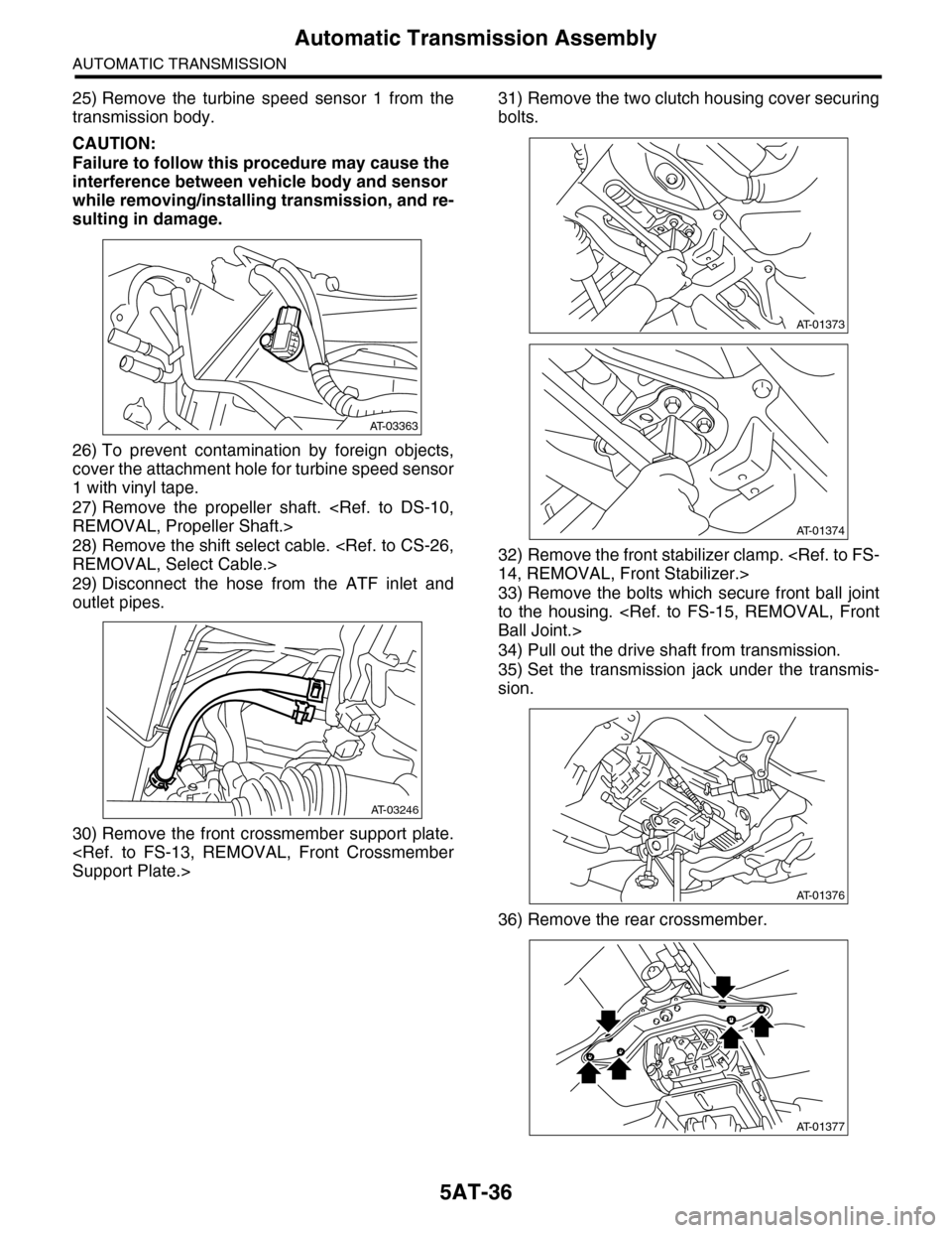
25) Remove the turbine speed sensor 1 from the
transmission body.
CAUTION:
Failure to follow this procedure may cause the
interference between vehicle body and sensor
while removing/installing transmission, and re-
sulting in damage.
26) To prevent contamination by foreign objects,
cover the attachment hole for turbine speed sensor
1 with vinyl tape.
27) Remove the propeller shaft.
28) Remove the shift select cable.
29) Disconnect the hose from the ATF inlet and
outlet pipes.
30) Remove the front crossmember support plate.
31) Remove the two clutch housing cover securing
bolts.
32) Remove the front stabilizer clamp.
33) Remove the bolts which secure front ball joint
to the housing.
34) Pull out the drive shaft from transmission.
35) Set the transmission jack under the transmis-
sion.
36) Remove the rear crossmember.
AT-03363
AT-03246
AT-01373
AT-01374
AT-01376
AT-01377
Page 2054 of 2453
5AT-38
Automatic Transmission Assembly
AUTOMATIC TRANSMISSION
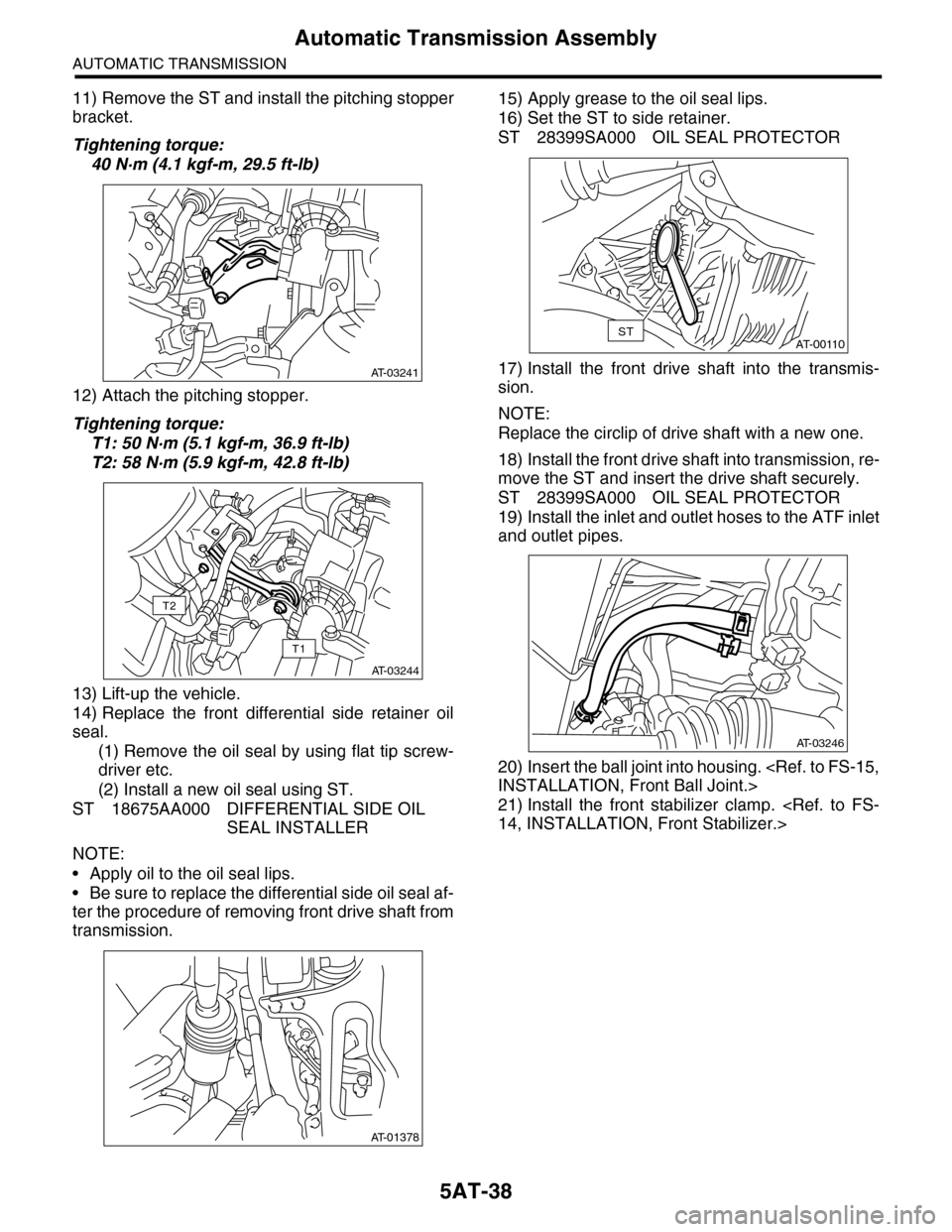
11) Remove the ST and install the pitching stopper
bracket.
Tightening torque:
40 N·m (4.1 kgf-m, 29.5 ft-lb)
12) Attach the pitching stopper.
Tightening torque:
T1: 50 N·m (5.1 kgf-m, 36.9 ft-lb)
T2: 58 N·m (5.9 kgf-m, 42.8 ft-lb)
13) Lift-up the vehicle.
14) Replace the front differential side retainer oil
seal.
(1) Remove the oil seal by using flat tip screw-
driver etc.
(2) Install a new oil seal using ST.
ST 18675AA000 DIFFERENTIAL SIDE OIL
SEAL INSTALLER
NOTE:
•Apply oil to the oil seal lips.
•Be sure to replace the differential side oil seal af-
ter the procedure of removing front drive shaft from
transmission.
15) Apply grease to the oil seal lips.
16) Set the ST to side retainer.
ST 28399SA000 OIL SEAL PROTECTOR
17) Install the front drive shaft into the transmis-
sion.
NOTE:
Replace the circlip of drive shaft with a new one.
18) Install the front drive shaft into transmission, re-
move the ST and insert the drive shaft securely.
ST 28399SA000 OIL SEAL PROTECTOR
19) Install the inlet and outlet hoses to the ATF inlet
and outlet pipes.
20) Insert the ball joint into housing.
21) Install the front stabilizer clamp.
AT-03241
AT-03244
T1
T2
AT-01378
AT-00110ST
AT-03246
Page 2056 of 2453
5AT-40
Automatic Transmission Assembly
AUTOMATIC TRANSMISSION
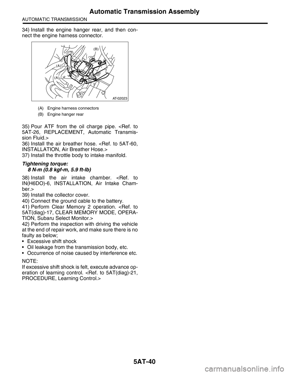
34) Install the engine hanger rear, and then con-
nect the engine harness connector.
35) Pour ATF from the oil charge pipe.
sion Fluid.>
36) Install the air breather hose.
37) Install the throttle body to intake manifold.
Tightening torque:
8 N·m (0.8 kgf-m, 5.9 ft-lb)
38) Install the air intake chamber.
ber.>
39) Install the collector cover.
40) Connect the ground cable to the battery.
41) Perform Clear Memory 2 operation.
TION, Subaru Select Monitor.>
42) Perform the inspection with driving the vehicle
at the end of repair work, and make sure there is no
faulty as below;
•Excessive shift shock
•Oil leakage from the transmission body, etc.
•Occurrence of noise caused by interference etc.
NOTE:
If excessive shift shock is felt, execute advance op-
eration of learning control.
(A) Engine harness connectors
(B) Engine hanger rear
(B)
(A)
(A)
AT-02023
Page 2062 of 2453
5AT-46
Inhibitor Switch
AUTOMATIC TRANSMISSION
13.Inhibitor Switch
A: INSPECTION
Inhibitor switch cannot be checked, because the in-
hibitor switch is installed on control valve assembly.
When a malfunction occurs, refer to 5AT (diag)
section.
(PRNDL INPUT), Diagnostic Procedure with Diag-
nostic Trouble Code (DTC).>
Page 2070 of 2453
5AT-54
Control Valve Body
AUTOMATIC TRANSMISSION
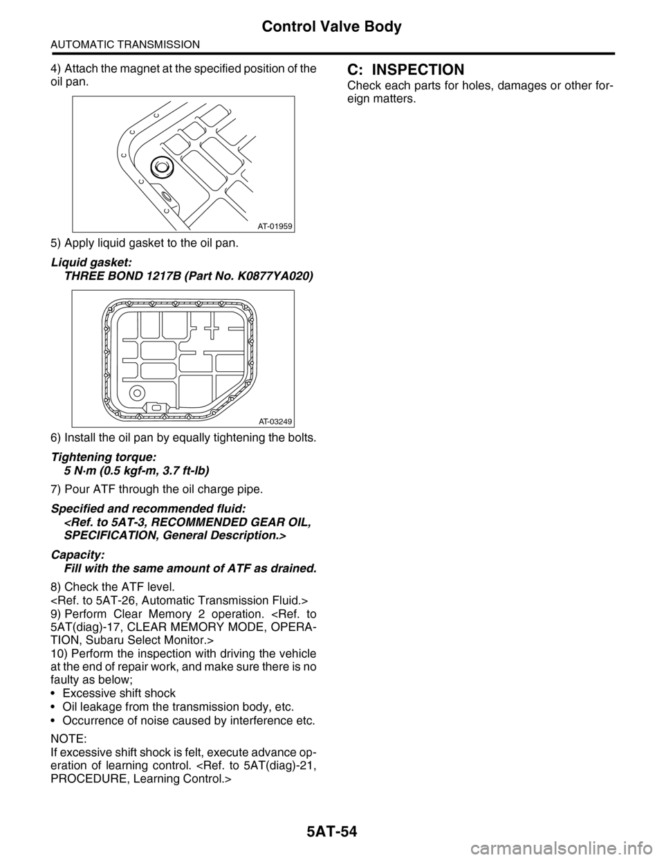
4) Attach the magnet at the specified position of the
oil pan.
5) Apply liquid gasket to the oil pan.
Liquid gasket:
THREE BOND 1217B (Part No. K0877YA020)
6) Install the oil pan by equally tightening the bolts.
Tightening torque:
5 N·m (0.5 kgf-m, 3.7 ft-lb)
7) Pour ATF through the oil charge pipe.
Specified and recommended fluid:
Capacity:
Fill with the same amount of ATF as drained.
8) Check the ATF level.
9) Perform Clear Memory 2 operation.
TION, Subaru Select Monitor.>
10) Perform the inspection with driving the vehicle
at the end of repair work, and make sure there is no
faulty as below;
•Excessive shift shock
•Oil leakage from the transmission body, etc.
•Occurrence of noise caused by interference etc.
NOTE:
If excessive shift shock is felt, execute advance op-
eration of learning control.
C: INSPECTION
Check each parts for holes, damages or other for-
eign matters.
AT-01959
AT-03249
Page 2072 of 2453
5AT-56
Transmission Control Module (TCM)
AUTOMATIC TRANSMISSION
19.Transmission Control Mod-
ule (TCM)
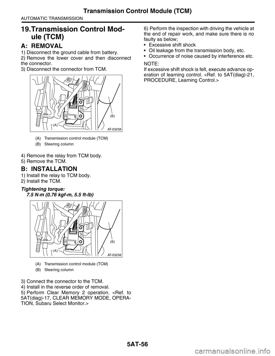
A: REMOVAL
1) Disconnect the ground cable from battery.
2) Remove the lower cover and then disconnect
the connector.
3) Disconnect the connector from TCM.
4) Remove the relay from TCM body.
5) Remove the TCM.
B: INSTALLATION
1) Install the relay to TCM body.
2) Install the TCM.
Tightening torque:
7.5 N·m (0.76 kgf-m, 5.5 ft-lb)
3) Connect the connector to the TCM.
4) Install in the reverse order of removal.
5) Perform Clear Memory 2 operation.
TION, Subaru Select Monitor.>
6) Perform the inspection with driving the vehicle at
the end of repair work, and make sure there is no
faulty as below;
•Excessive shift shock
•Oil leakage from the transmission body, etc.
•Occurrence of noise caused by interference etc.
NOTE:
If excessive shift shock is felt, execute advance op-
eration of learning control.
(A) Transmission control module (TCM)
(B) Steering column
(A) Transmission control module (TCM)
(B) Steering column
AT-03258(A)
(B)
AT-03258(A)
(B)
Page 2084 of 2453
5AT-68
Reduction Driven Gear
AUTOMATIC TRANSMISSION
27.Reduction Driven Gear
A: REMOVAL
1) Remove the transmission assembly from vehicle
body.
2) Remove the rear wheel speed sensor, and sep-
arate the extension case from transmission case.
3) Remove the center differential carrier.
4) Set the range select lever to the “P” range.
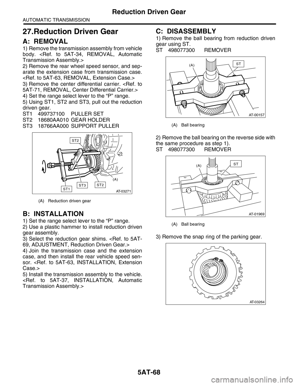
5) Using ST1, ST2 and ST3, pull out the reduction
driven gear.
ST1 499737100 PULLER SET
ST2 18680AA010 GEAR HOLDER
ST3 18766AA000 SUPPORT PULLER
B: INSTALLATION
1) Set the range select lever to the “P” range.
2) Use a plastic hammer to install reduction driven
gear assembly.
3) Select the reduction gear shims.
4) Join the transmission case and the extension
case, and then install the rear vehicle speed sen-
sor.
5) Install the transmission assembly to the vehicle.
C: DISASSEMBLY
1) Remove the ball bearing from reduction driven
gear using ST.
ST 498077300 REMOVER
2) Remove the ball bearing on the reverse side with
the same procedure as step 1).
ST 498077300 REMOVER
3) Remove the snap ring of the parking gear.
(A) Reduction driven gear
AT-03271
ST2ST1
ST2
ST3
(A)
(A) Ball bearing
(A) Ball bearing
AT-00157
(A)ST
AT-01969
(A)ST
AT-03264