cylinder SUBARU TRIBECA 2009 1.G Service Repair Manual
[x] Cancel search | Manufacturer: SUBARU, Model Year: 2009, Model line: TRIBECA, Model: SUBARU TRIBECA 2009 1.GPages: 2453, PDF Size: 46.32 MB
Page 1721 of 2453
GD(H6DO)-109
Diagnostic Trouble Code (DTC) Detecting Criteria
GENERAL DESCRIPTION
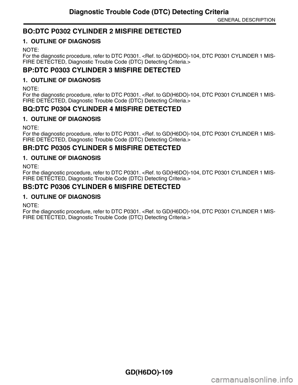
BO:DTC P0302 CYLINDER 2 MISFIRE DETECTED
1. OUTLINE OF DIAGNOSIS
NOTE:
For the diagnostic procedure, refer to DTC P0301.
BP:DTC P0303 CYLINDER 3 MISFIRE DETECTED
1. OUTLINE OF DIAGNOSIS
NOTE:
For the diagnostic procedure, refer to DTC P0301.
BQ:DTC P0304 CYLINDER 4 MISFIRE DETECTED
1. OUTLINE OF DIAGNOSIS
NOTE:
For the diagnostic procedure, refer to DTC P0301.
BR:DTC P0305 CYLINDER 5 MISFIRE DETECTED
1. OUTLINE OF DIAGNOSIS
NOTE:
For the diagnostic procedure, refer to DTC P0301.
BS:DTC P0306 CYLINDER 6 MISFIRE DETECTED
1. OUTLINE OF DIAGNOSIS
NOTE:
For the diagnostic procedure, refer to DTC P0301.
Page 1729 of 2453
GD(H6DO)-117
Diagnostic Trouble Code (DTC) Detecting Criteria
GENERAL DESCRIPTION
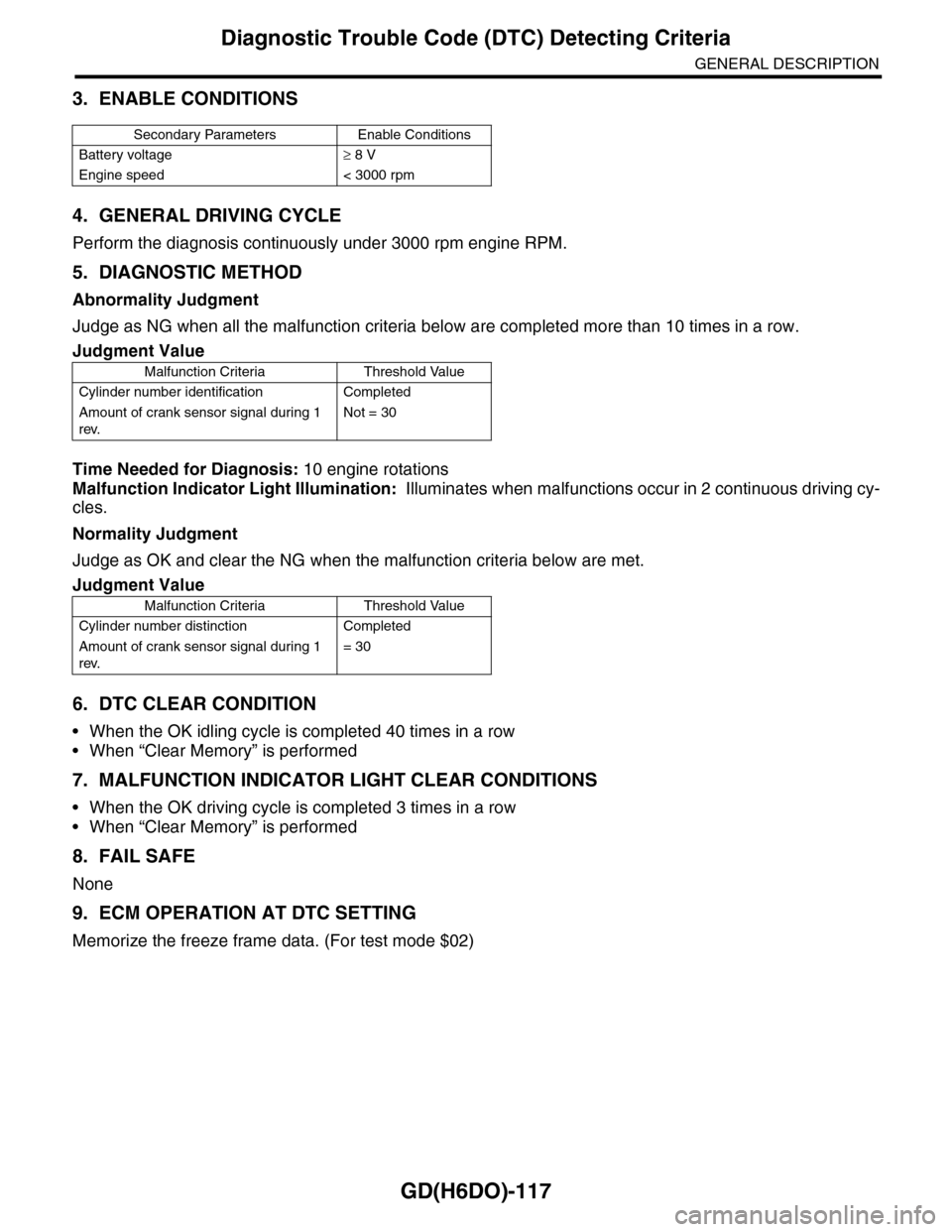
3. ENABLE CONDITIONS
4. GENERAL DRIVING CYCLE
Perform the diagnosis continuously under 3000 rpm engine RPM.
5. DIAGNOSTIC METHOD
Abnormality Judgment
Judge as NG when all the malfunction criteria below are completed more than 10 times in a row.
Time Needed for Diagnosis: 10 engine rotations
Malfunction Indicator Light Illumination: Illuminates when malfunctions occur in 2 continuous driving cy-
cles.
Normality Judgment
Judge as OK and clear the NG when the malfunction criteria below are met.
6. DTC CLEAR CONDITION
•When the OK idling cycle is completed 40 times in a row
•When “Clear Memory” is performed
7. MALFUNCTION INDICATOR LIGHT CLEAR CONDITIONS
•When the OK driving cycle is completed 3 times in a row
•When “Clear Memory” is performed
8. FAIL SAFE
None
9. ECM OPERATION AT DTC SETTING
Memorize the freeze frame data. (For test mode $02)
Secondary Parameters Enable Conditions
Battery voltage≥ 8 V
Engine speed < 3000 rpm
Judgment Value
Malfunction Criteria Threshold Value
Cylinder number identification Completed
Amount of crank sensor signal during 1
rev.
Not = 30
Judgment Value
Malfunction Criteria Threshold Value
Cylinder number distinction Completed
Amount of crank sensor signal during 1
rev.
= 30
Page 1781 of 2453
GD(H6DO)-169
Diagnostic Trouble Code (DTC) Detecting Criteria
GENERAL DESCRIPTION
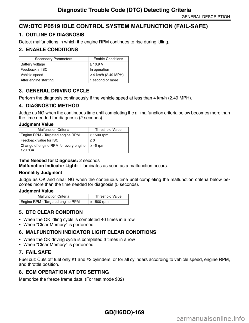
CW:DTC P0519 IDLE CONTROL SYSTEM MALFUNCTION (FAIL-SAFE)
1. OUTLINE OF DIAGNOSIS
Detect malfunctions in which the engine RPM continues to rise during idling.
2. ENABLE CONDITIONS
3. GENERAL DRIVING CYCLE
Perform the diagnosis continuously if the vehicle speed at less than 4 km/h (2.49 MPH).
4. DIAGNOSTIC METHOD
Judge as NG when the continuous time until completing the all malfunction criteria below becomes more than
the time needed for diagnosis (2 seconds).
Time Needed for Diagnosis: 2 seconds
Malfunction Indicator Light: Illuminates as soon as a malfunction occurs.
Normality Judgment
Judge as OK and clear NG when the continuous time until completing the malfunction criteria below be-
comes more than the time needed for diagnosis (5 seconds).
5. DTC CLEAR CONDITION
•When the OK idling cycle is completed 40 times in a row
•When “Clear Memory” is performed
6. MALFUNCTION INDICATOR LIGHT CLEAR CONDITIONS
•When the OK driving cycle is completed 3 times in a row
•When “Clear Memory” is performed
7. FAIL SAFE
Fuel cut: Cuts off fuel only #1 and #2 cylinders, or for all cylinders according to vehicle speed, engine RPM,
and throttle position.
8. ECM OPERATION AT DTC SETTING
Memorize the freeze frame data. (For test mode $02)
Secondary Parameters Enable Conditions
Battery voltage≥ 10.9 V
Feedback in ISC In operation
Ve h i c l e s p e e d < 4 k m / h ( 2 . 4 9 M P H )
After engine starting 1 second or more
Judgment Value
Malfunction Criteria Threshold Value
Engine RPM - Targeted engine RPM≥ 1500 rpm
Feedback value for ISC≤ 0
Change of engine RPM for every engine
120 °CA
≥ –5 rpm
Judgment Value
Malfunction Criteria Threshold Value
Engine RPM - Targeted engine RPM < 1500 rpm
Page 1860 of 2453
LU(H6DO)-11
Oil Pan and Strainer
LUBRICATION
6. Oil Pan and Strainer
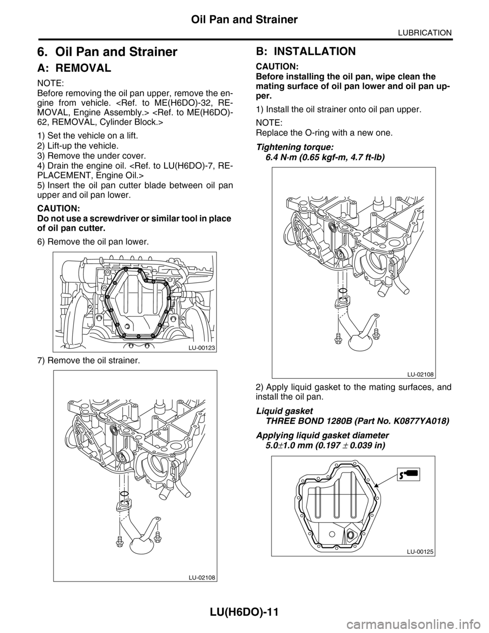
A: REMOVAL
NOTE:
Before removing the oil pan upper, remove the en-
gine from vehicle.
1) Set the vehicle on a lift.
2) Lift-up the vehicle.
3) Remove the under cover.
4) Drain the engine oil.
5) Insert the oil pan cutter blade between oil pan
upper and oil pan lower.
CAUTION:
Do not use a screwdriver or similar tool in place
of oil pan cutter.
6) Remove the oil pan lower.
7) Remove the oil strainer.
B: INSTALLATION
CAUTION:
Before installing the oil pan, wipe clean the
mating surface of oil pan lower and oil pan up-
per.
1) Install the oil strainer onto oil pan upper.
NOTE:
Replace the O-ring with a new one.
Tightening torque:
6.4 N·m (0.65 kgf-m, 4.7 ft-lb)
2) Apply liquid gasket to the mating surfaces, and
install the oil pan.
Liquid gasket
THREE BOND 1280B (Part No. K0877YA018)
Applying liquid gasket diameter
5.0±1.0 mm (0.197 ± 0.039 in)
LU-00123
LU-02108
LU-02108
LU-00125
Page 1868 of 2453
ME(H6DO)-2
General Description
MECHANICAL
1. General Description
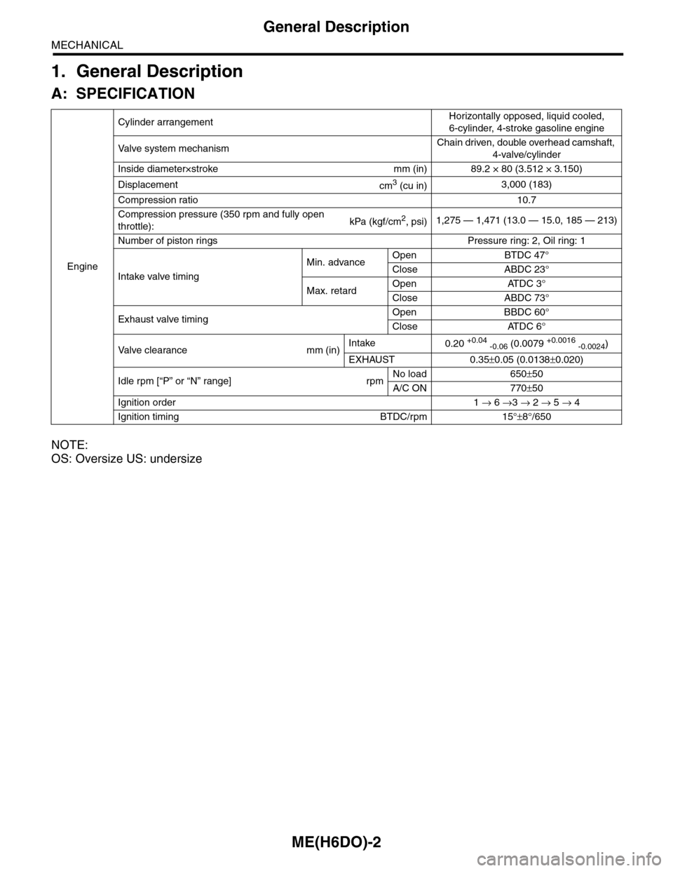
A: SPECIFICATION
NOTE:
OS: Oversize US: undersize
Engine
Cylinder arrangementHorizontally opposed, liquid cooled,
6-cylinder, 4-stroke gasoline engine
Va l ve s y s t e m m e c h a n i s mChain driven, double overhead camshaft,
4-valve/cylinder
Inside diameter×stroke mm (in) 89.2 × 80 (3.512 × 3.150)
Displacementcm3 (cu in)3,000 (183)
Compression ratio10.7
Compression pressure (350 rpm and fully open
throttle):kPa (kgf/cm2, psi)1,275 — 1,471 (13.0 — 15.0, 185 — 213)
Number of piston rings Pressure ring: 2, Oil ring: 1
Intake valve timing
Min. advanceOpen BTDC 47°
Close ABDC 23°
Max. retardOpen ATDC 3°
Close ABDC 73°
Exhaust valve timingOpen BBDC 60°
Close ATDC 6°
Va l ve c l e a r a n c e m m ( i n )Intake0.20 +0.04 -0.06 (0.0079 +0.0016 -0.0024)
EXHAUST 0.35±0.05 (0.0138±0.020)
Idle rpm [“P” or “N” range] rpmNo load 650±50
A/C ON 770±50
Ignition order 1 → 6 →3 → 2 → 5 → 4
Ignition timing BTDC/rpm 15°±8°/650
Page 1869 of 2453
ME(H6DO)-3
General Description
MECHANICAL
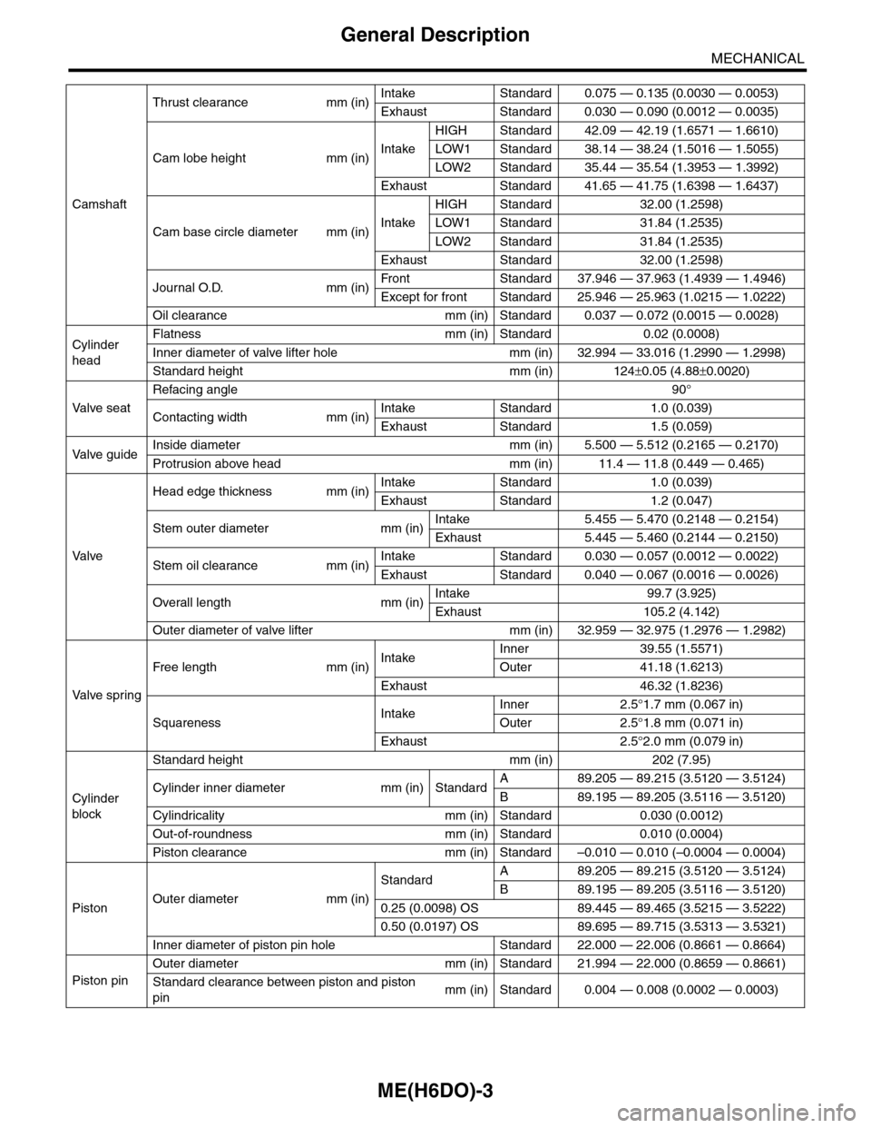
Camshaft
Thrust clearance mm (in)Intake Standard 0.075 — 0.135 (0.0030 — 0.0053)
Exhaust Standard 0.030 — 0.090 (0.0012 — 0.0035)
Cam lobe height mm (in)Intake
HIGH Standard 42.09 — 42.19 (1.6571 — 1.6610)
LOW1 Standard 38.14 — 38.24 (1.5016 — 1.5055)
LOW2 Standard 35.44 — 35.54 (1.3953 — 1.3992)
Exhaust Standard 41.65 — 41.75 (1.6398 — 1.6437)
Cam base circle diameter mm (in)Intake
HIGH Standard 32.00 (1.2598)
LOW1 Standard 31.84 (1.2535)
LOW2 Standard 31.84 (1.2535)
Exhaust Standard 32.00 (1.2598)
Journal O.D. mm (in)Fr o nt S ta n da r d 3 7. 9 46 — 3 7 . 96 3 ( 1 . 49 3 9 — 1. 4 9 46 )
Except for front Standard 25.946 — 25.963 (1.0215 — 1.0222)
Oil clearance mm (in) Standard 0.037 — 0.072 (0.0015 — 0.0028)
Cylinder
head
Flatness mm (in) Standard 0.02 (0.0008)
Inner diameter of valve lifter hole mm (in) 32.994 — 33.016 (1.2990 — 1.2998)
Standard height mm (in) 124±0.05 (4.88±0.0020)
Va l ve s e a t
Refacing angle90°
Contacting width mm (in)Intake Standard 1.0 (0.039)
Exhaust Standard 1.5 (0.059)
Va l ve g u i d eInside diameter mm (in) 5.500 — 5.512 (0.2165 — 0.2170)
Protrusion above head mm (in) 11.4 — 11.8 (0.449 — 0.465)
Va l ve
Head edge thickness mm (in)Intake Standard 1.0 (0.039)
Exhaust Standard 1.2 (0.047)
Stem outer diameter mm (in)Intake 5.455 — 5.470 (0.2148 — 0.2154)
Exhaust 5.445 — 5.460 (0.2144 — 0.2150)
Stem oil clearance mm (in)Intake Standard 0.030 — 0.057 (0.0012 — 0.0022)
Exhaust Standard 0.040 — 0.067 (0.0016 — 0.0026)
Overall length mm (in)Intake 99.7 (3.925)
Exhaust 105.2 (4.142)
Outer diameter of valve lifter mm (in) 32.959 — 32.975 (1.2976 — 1.2982)
Va l ve s p r i n g
Free length mm (in)IntakeInner 39.55 (1.5571)
Outer 41.18 (1.6213)
Exhaust 46.32 (1.8236)
SquarenessIntakeInner 2.5°1.7 mm (0.067 in)
Outer 2.5°1.8 mm (0.071 in)
Exhaust 2.5°2.0 mm (0.079 in)
Cylinder
block
Standard height mm (in) 202 (7.95)
Cylinder inner diameter mm (in) StandardA89.205 — 89.215 (3.5120 — 3.5124)
B89.195 — 89.205 (3.5116 — 3.5120)
Cylindricality mm (in) Standard 0.030 (0.0012)
Out-of-roundness mm (in) Standard 0.010 (0.0004)
Piston clearance mm (in) Standard –0.010 — 0.010 (–0.0004 — 0.0004)
PistonOuter diameter mm (in)
StandardA89.205 — 89.215 (3.5120 — 3.5124)
B89.195 — 89.205 (3.5116 — 3.5120)
0.25 (0.0098) OS 89.445 — 89.465 (3.5215 — 3.5222)
0.50 (0.0197) OS 89.695 — 89.715 (3.5313 — 3.5321)
Inner diameter of piston pin hole Standard 22.000 — 22.006 (0.8661 — 0.8664)
Piston pin
Outer diameter mm (in) Standard 21.994 — 22.000 (0.8659 — 0.8661)
Standard clearance between piston and piston
pinmm (in) Standard 0.004 — 0.008 (0.0002 — 0.0003)
Page 1874 of 2453
ME(H6DO)-8
General Description
MECHANICAL
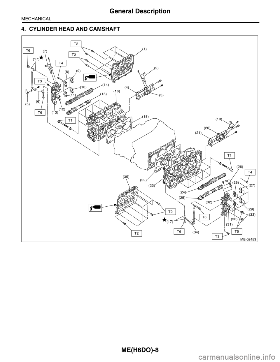
4. CYLINDER HEAD AND CAMSHAFT
ME-02453
(1)
(2)
(3)
(4)
(9)
(10)
(22)
(23)
(24)
(26)
(27)(28)
(25)
(32)
(8)
(18)
(16)
(13)(12)
(6)(5)
(14)
(15)
(19)
(20)
(21)
(7)
(11)
(31)
(34)
(35)
(30)
(29)
(33)
T3
T1
T4
T2
T2
T1
T4
T5
T2
T2T3
T6
T6
T6
T6
(17)
(17)
Page 1875 of 2453
ME(H6DO)-9
General Description
MECHANICAL
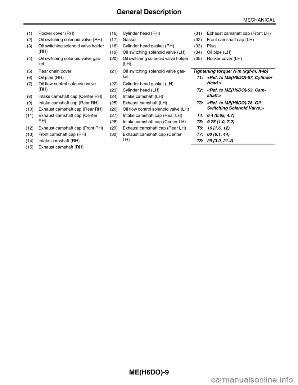
(1) Rocker cover (RH) (16) Cylinder head (RH) (31) Exhaust camshaft cap (Front LH)
(2) Oil switching solenoid valve (RH) (17) Gasket (32) Front camshaft cap (LH)
(3) Oil switching solenoid valve holder
(RH)
(18) Cylinder head gasket (RH) (33) Plug
(19) Oil switching solenoid valve (LH) (34) Oil pipe (LH)
(4) Oil switching solenoid valve gas-
ket
(20) Oil switching solenoid valve holder
(LH)
(35) Rocker cover (LH)
(5) Rear chain cover (21) Oil switching solenoid valve gas-
ket
Tightening torque: N·m (kgf-m, ft-lb)
(6) Oil pipe (RH)T1:
(RH)
(22) Cylinder head gasket (LH)
(23) Cylinder head (LH)T2:
(9) Intake camshaft cap (Rear RH) (25) Exhaust camshaft (LH)T3:
(11) Exhaust camshaft cap (Center
RH)
(27) Intake camshaft cap (Rear LH)T4:6.4 (0.65, 4.7)
(28) Intake camshaft cap (Center LH)T5: 9.75 (1.0, 7.2)
(12) Exhaust camshaft cap (Front RH) (29) Exhaust camshaft cap (Rear LH)T6:16 (1.6, 12)
(13) Front camshaft cap (RH) (30) Exhaust camshaft cap (Center
LH)
T7: 60 (6.1, 44)
(14) Intake camshaft (RH)T8: 29 (3.0, 21.4)
(15) Exhaust camshaft (RH)
Page 1876 of 2453
ME(H6DO)-10
General Description
MECHANICAL
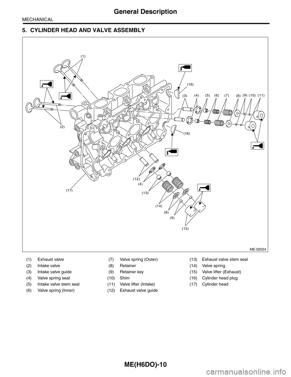
5. CYLINDER HEAD AND VALVE ASSEMBLY
(1) Exhaust valve (7) Valve spring (Outer) (13) Exhaust valve stem seal
(2) Intake valve (8) Retainer (14) Valve spring
(3) Intake valve guide (9) Retainer key (15) Valve lifter (Exhaust)
(4) Valve spring seat (10) Shim (16) Cylinder head plug
(5) Intake valve stem seal (11) Valve lifter (Intake) (17) Cylinder head
(6) Valve spring (Inner) (12) Exhaust valve guide
ME-02024
(16)
(16)
(17)
(3)
(12)
(13)
(4)
(14)
(8)
(9)
(15)
(4) (5) (6)(7)(8)(9)(11)(10)
(1)
(2)
Page 1877 of 2453
ME(H6DO)-11
General Description
MECHANICAL
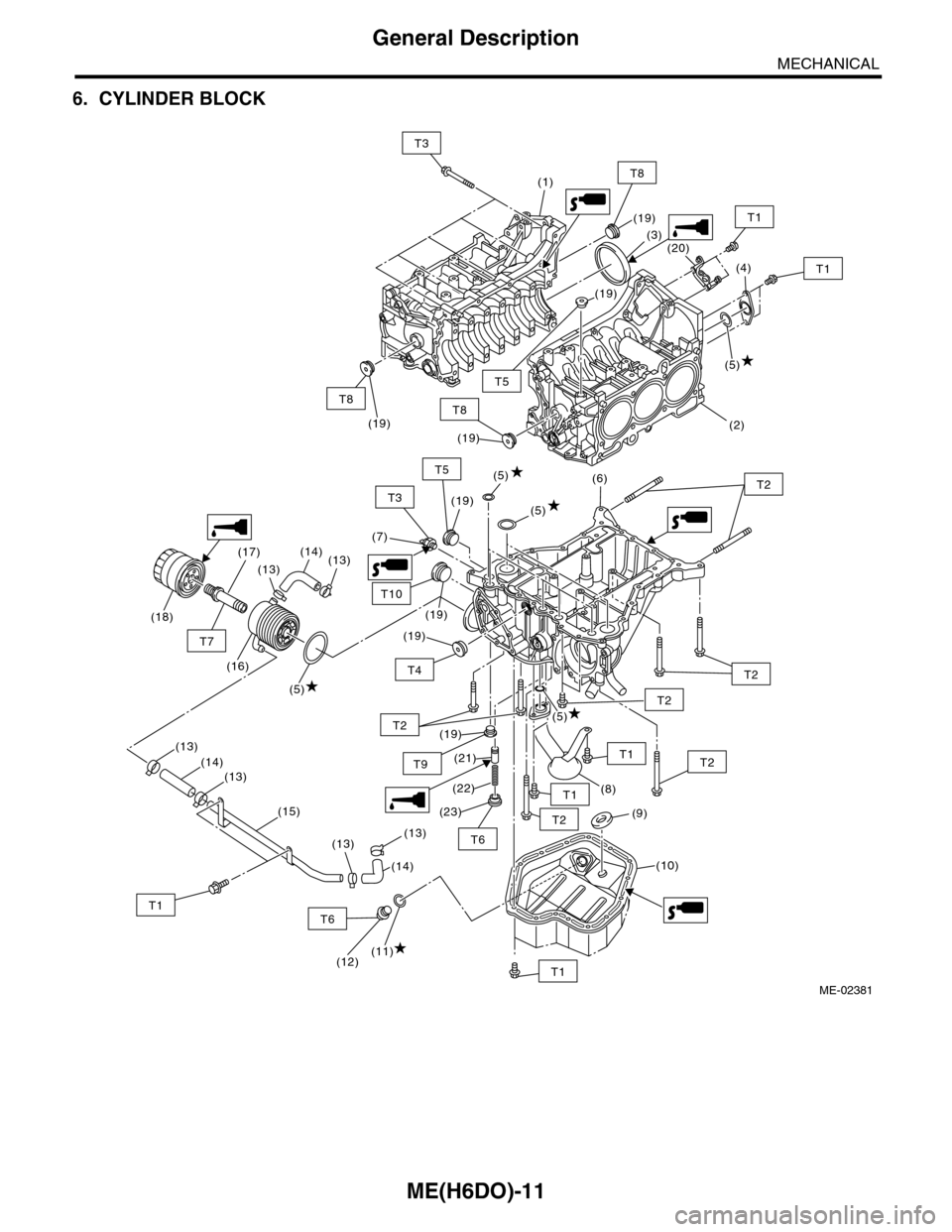
6. CYLINDER BLOCK
(5)
(6)
(7)
(9)
(5)
(8)
(19)
(19)
(10)
(19)
(19)
(21)
(22)
(23)
T1
T2
T2
T2
T1
T2
T2T5
T2
T9
ME-02381
T4
T6
T10
(5)
(1)
(3)
(4)
(5)
(2)
(19)
(19)
(20)
(19)(19)
T1
T1
T8
T3
T5
T8T8
(5)
(18)
(17)
(13)
(14)(13)
(16)
(13)
(14)(13)
(15)
(13)(13)
(11)(12)
(14)
T6T1
T7
T3
T1