SUZUKI GRAND VITARA 1987 Service Repair Manual
Manufacturer: SUZUKI, Model Year: 1987, Model line: GRAND VITARA, Model: SUZUKI GRAND VITARA 1987Pages: 962, PDF Size: 27.87 MB
Page 201 of 962
Coolant
The coolant recovery system is standard. The
coolant in the radiator expands with heat, and
the overflow is collected in the reservoir tank.
When the system cools down, the coolant is
drawn back into the radiator.
The cooling system has been filled at the factory
with a quality coolant that is either 50/50
mixture of water and GOLDEN CRUISER
1200 or 30/70 mixture of water and GOLDEN
CRUISER 1200.
The 50/50 mixture coolant solution provides
freezing protection to -36°C (-33”F), the
30/70 mixture coolant solution provides freezing.
protection to -16°C (3” F).
GOLDEN CRUISER 1200 - “Anti-freeze and
Summer Coolant” - its effects
1) Its freezing temperature is much lower and
depends on the concentration of GOLDEN
CRUISER 1200. It is an anti-freeze coolant.
2) It does not corrode the metal surfaces of the
cooling circuit.It is an anti-corrosion
coolant.
3) It does not develop foam or bubbles. It is a
foam-inhibited coolant.
When changing the engine coolant, use mixture
of 50% water and 50% GOLDEN CRUISER
1200 for the market where ambient tempera-
ture falls lower than -16°C (3°F) in winter and
mixture of 70% water and 30% GOLDEN
CRUISER 1200 for the market where am-
bient temperature doesn’t fall lower than -16°C
(3” F).
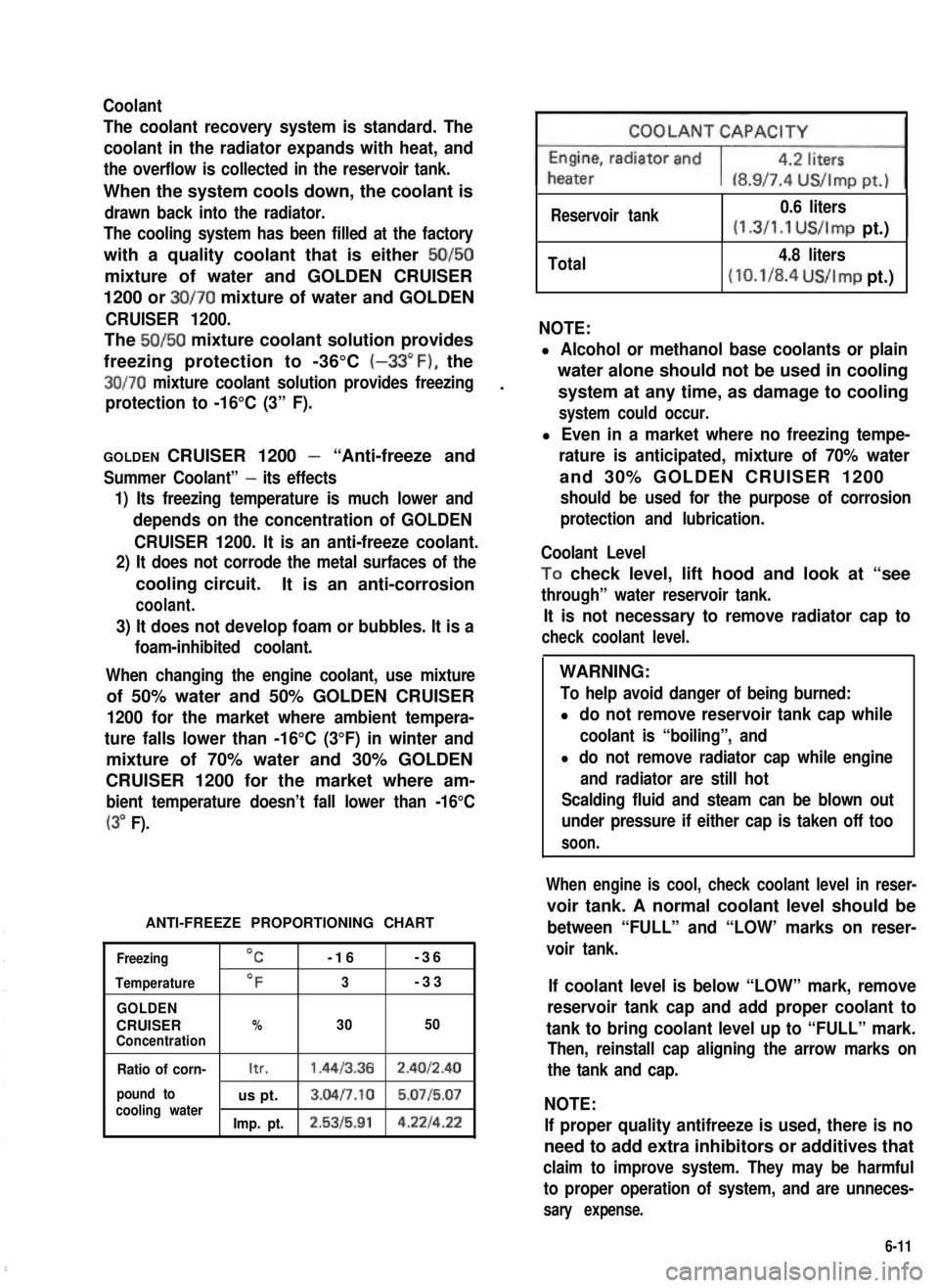
ANTI-FREEZE PROPORTIONING CHART
Freezing
Temperature
GOLDEN
CRUISERConcentration
OC-16-36
OF3-33
%3050
Ratio of corn-Itr.1.4413.362.4012.40
pound tous pt.3.04l7.10 5.0715.07cooling waterImp. pt.2.5315.914.221422
Reservoir tank0.6 liters
(1.3/1.1 US/Imp pt.)I
Total4.8 liters
(10.1/8.4 US/Imp pt.)
NOTE:
l Alcohol or methanol base coolants or plain
water alone should not be used in cooling
system at any time, as damage to cooling
system could occur.
l Even in a market where no freezing tempe-
rature is anticipated, mixture of 70% water
and 30% GOLDEN CRUISER 1200
should be used for the purpose of corrosion
protection and lubrication.
Coolant Level
,To check level, lift hood and look at “see
through” water reservoir tank.
It is not necessary to remove radiator cap to
check coolant level.
WARNING:
To help avoid danger of being burned:
l do not remove reservoir tank cap while
coolant is “boiling”, and
l do not remove radiator cap while engine
and radiator are still hot
Scalding fluid and steam can be blown out
under pressure if either cap is taken off too
soon.
When engine is cool, check coolant level in reser-
voir tank. A normal coolant level should be
between “FULL” and “LOW’ marks on reser-
voir tank.
If coolant level is below “LOW” mark, remove
reservoir tank cap and add proper coolant to
tank to bring coolant level up to “FULL” mark.
Then, reinstall cap aligning the arrow marks on
the tank and cap.
NOTE:
If proper quality antifreeze is used, there is no
need to add extra inhibitors or additives that
claim to improve system. They may be harmful
to proper operation of system, and are unneces-
sary expense.
6-11
Page 202 of 962
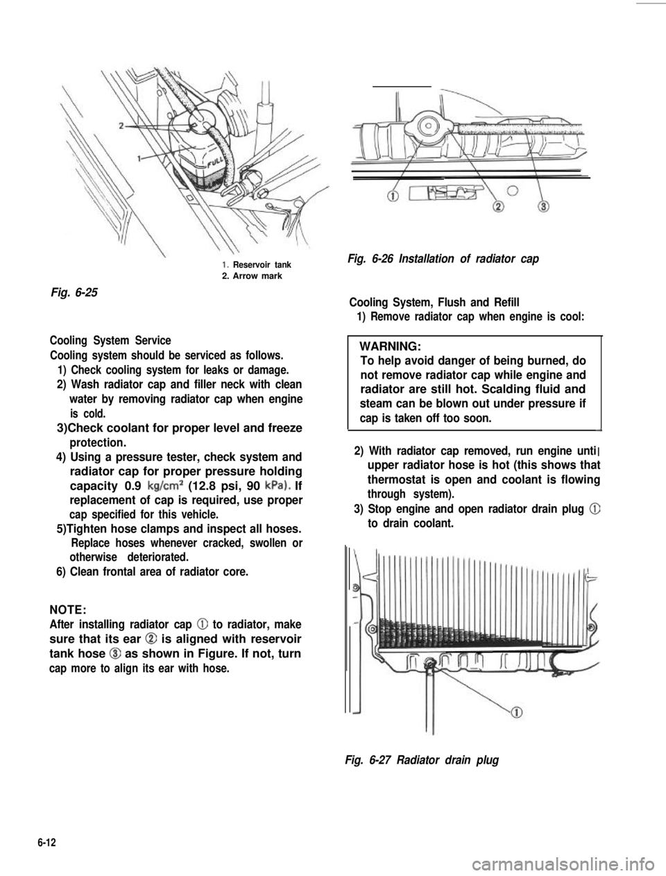
Fig. 6-25
1. Reservoir tank
2. Arrow mark
Cooling System Service
Cooling system should be serviced as follows.
1) Check cooling system for leaks or damage.
2) Wash radiator cap and filler neck with clean
water by removing radiator cap when engine
is cold.
3)Check coolant for proper level and freeze
protection.
4) Using a pressure tester, check system and
radiator cap for proper pressure holding
capacity 0.9 kg/cm2 (12.8 psi, 90 kPa). If
replacement of cap is required, use proper
cap specified for this vehicle.
5)Tighten hose clamps and inspect all hoses.
Replace hoses whenever cracked, swollen or
otherwise deteriorated.
6) Clean frontal area of radiator core.
NOTE:
After installing radiator cap 0 to radiator, make
sure that its ear @ is aligned with reservoir
tank hose @I as shown in Figure. If not, turn
cap more to align its ear with hose.
Fig. 6-26 Installation of radiator cap
Cooling System, Flush and Refill
1) Remove radiator cap when engine is cool:
WARNING:
To help avoid danger of being burned, do
not remove radiator cap while engine and
radiator are still hot. Scalding fluid and
steam can be blown out under pressure if
cap is taken off too soon.d
I2) With radiator cap removed, run engine unti. .upper radiator hose is hot (this shows that
thermostat is open and coolant is flowing
through system).
3) Stop engine and open radiator drain plug @
to drain coolant.
Fig. 6-27 Radiator drain plug
6-12
Page 203 of 962
4) Close drain plug. Add water until system is
filled and run engine until upper radiator
hose is hot again.
5) Repeat steps 3) and 4) several times until
drained liquid is nearly colorless.
6) Drain system and then close radiator drain
plug tightly.
7) Disconnect hose from water reservoir tank.
Remove tank and pour out any fluid. Scrub
and clean inside of tank with soap and water.
Flush it well with clean water and drain.
Reinstall tank and hose.
8)Add proper mixture coolant (refer to page
6-11 of GOLDEN CRUISER 1200 and _,
water to radiator and tank.
Fill radiator to the base of radiator filler
neck and reservoir tank to “FULL” level
mark. Reinstall reservoir tank cap, aligning
the arrow marks on the tank and cap.
9) Run engine, with rediator cap removed, until
radiator upper hose is hot.
10) With engine idling, add coolant to radiator
until level reaches the bottom of filler neck.
Install radiator cap, making sure that the ear
of cap lines up with reservoir tank hose.
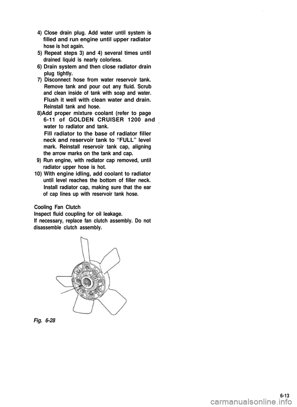
Cooling Fan Clutch
Inspect fluid coupling for oil leakage.
If necessary, replace fan clutch assembly. Do not
disassemble clutch assembly.
Fig. 6-28
6-13
Page 204 of 962
7-1.
7-2.
7-3.
7-4.
SECTION 7
CAR HEATER
CONTENTS
DESCRIPTION.. . . . . . . . . . . . . . . . . . . . . . . . . .. . . . . . . . . . . . . . . . . .7-27-
ELECTRICAL CIRCUIT
HEATER SERVICES........................................7-4
REMOVAL AND INSTALLATION..............................7-5
......................................7-3
7-1
Page 205 of 962
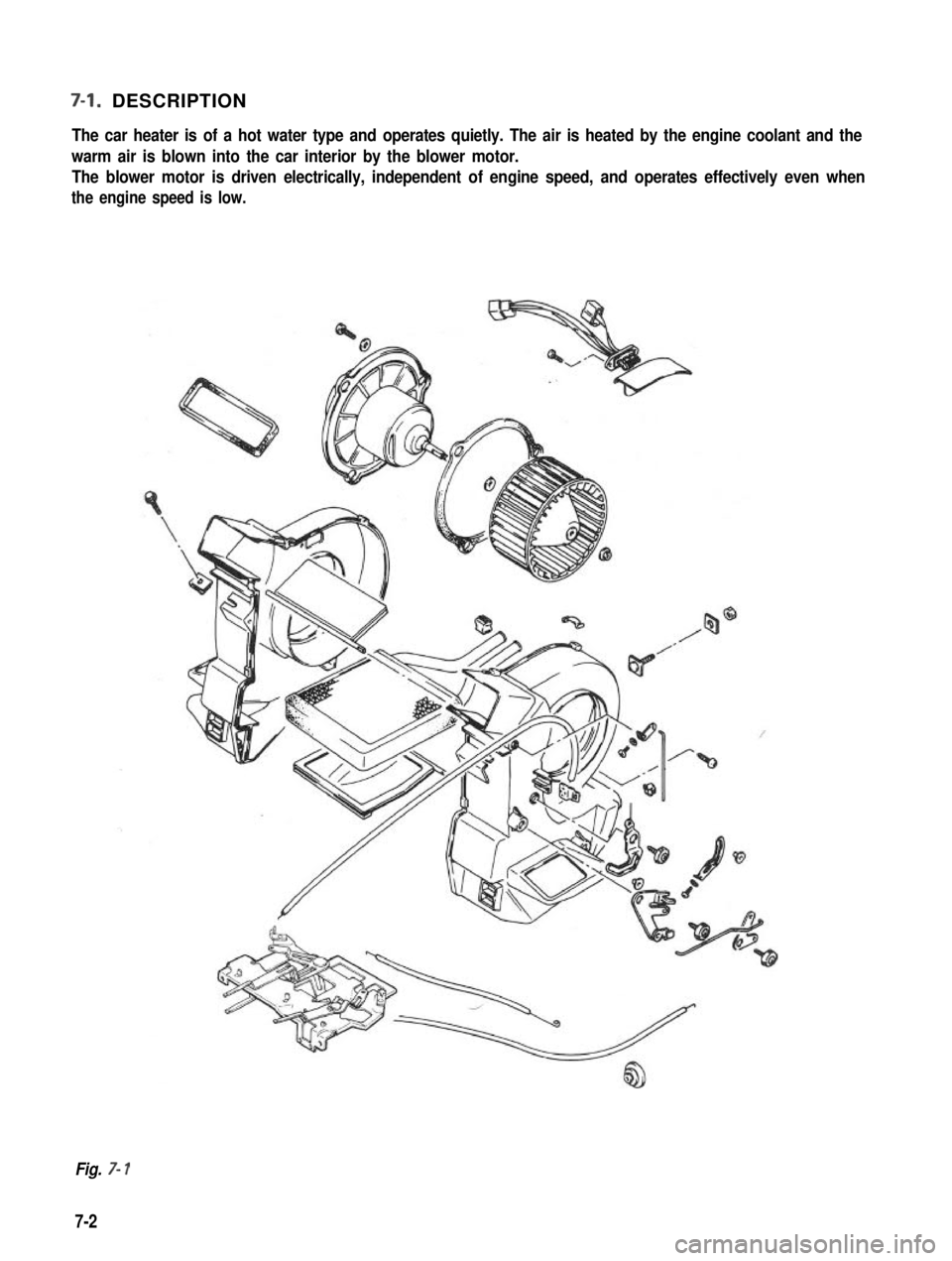
7-l. DESCRIPTION
The car heater is of a hot water type and operates quietly. The air is heated by the engine coolant and the
warm air is blown into the car interior by the blower motor. The blower motor is driven electrically, independent of engine speed, and operates effectively even when
the engine speed is low.
Fig. 7- 1
7-2
Page 206 of 962
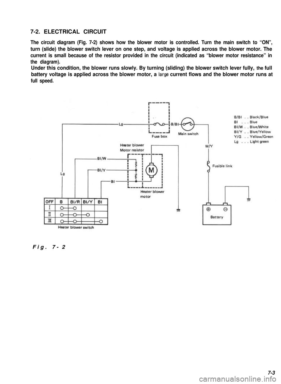
7-2. ELECTRICAL CIRCUIT
The circuit diagram (Fig. 7-2) shows how the blower motor is controlled. Turn the main switch to “ON”,
turn (slide) the blower switch lever on one step, and voltage is applied across the blower motor. The
current is small because of the resistor provided in the circuit (indicated as “blower motor resistance” in
the diagram).
Under this condition, the blower runs slowly. By turning (sliding) the blower switch lever fully, the full
battery voltage is applied across the blower motor, a large current flows and the blower motor runs at
full speed.
r-mm-1
ri
BlBl . .Black/Blue
LaBI . . . Blue
BIIW . .Blue/White
BUY . .Blue/Yellow
Y/G . .Yellow/Green
Heater blowerLa . . . Light green
Motor resistor
,,w~
motor
Heater blower switch
Fusible link
I
Fig. 7-2
7-3
Page 207 of 962
7-3. HEATER SERVICES
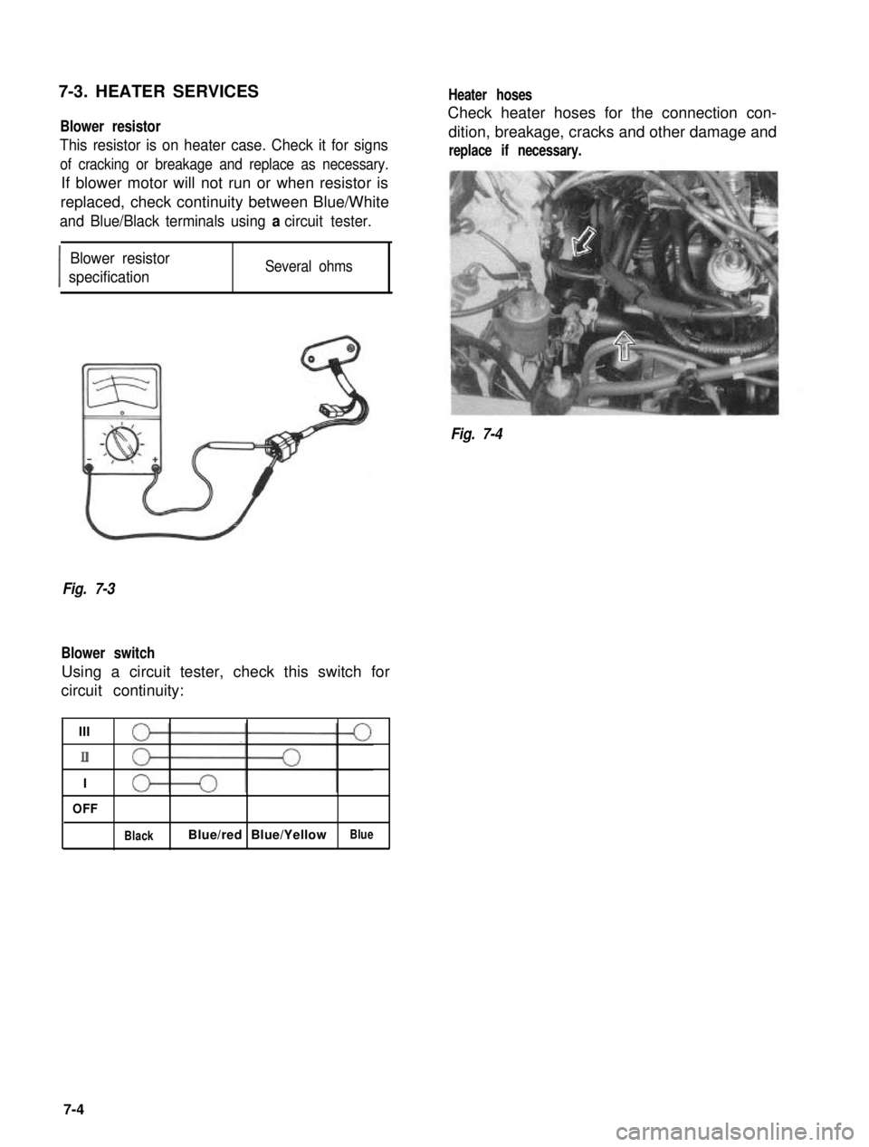
Blower resistor
This resistor is on heater case. Check it for signs
of cracking or breakage and replace as necessary.
If blower motor will not run or when resistor is
replaced, check continuity between Blue/White
and Blue/Black terminals using a circuit tester.
I
Blower resistor
specificationSeveral ohms
Heater hoses
Check heater hoses for the connection con-
dition, breakage, cracks and other damage and
replace if necessary.
Fig. 7-4
Fig. 7-3
Blower switch
Using a circuit tester, check this switch for
circuit continuity:
III
II
I
OFF
BlackBlue/red Blue/YellowBlue
7-4
Page 208 of 962
![SUZUKI GRAND VITARA 1987 Service Repair Manual 7-4. REMOVAL AND INSTALLATION
Removal
[Heater and blower motor]
1. Disconnect battery negative cable.
2. Drain cooling system.
WARNING:
To help avoid the danger of being burned, do
not remove the drai SUZUKI GRAND VITARA 1987 Service Repair Manual 7-4. REMOVAL AND INSTALLATION
Removal
[Heater and blower motor]
1. Disconnect battery negative cable.
2. Drain cooling system.
WARNING:
To help avoid the danger of being burned, do
not remove the drai](/img/20/57437/w960_57437-207.png)
7-4. REMOVAL AND INSTALLATION
Removal
[Heater and blower motor]
1. Disconnect battery negative cable.
2. Drain cooling system.
WARNING:
To help avoid the danger of being burned, do
not remove the drain plug and the radiator
cap while the engine and radiator are still hot.
Scalding fluid and steam can be blown out
under pressure if the plug and cap are taken
off too soon.
Fig 7-51. Drain plug2. Radiator
3. Disconnect heater inlet and outlet hoses
from heater unit pipes.
4. Remove instrument panel ass’y with speedo-
meter ass’y as follows.
1) Take off horn pad and remove steering
wheel using special tool @.
2) If equipped with radio and cigarette lighter,
disconnect radio and cigarette lighter lead
wires, and pull out radio case with radio
and cigarette lighter after loosening case
stay screw, and remove radio case bracket.
3) Pull out ashtray and loosen ashtray plate
screws.
4) Disconnect front food opening cable from
lock ass’y.
5) Loosen panel box stay screw and hood
opening cable lock nut on back side of
panel box cover.
6) Disconnect lead wires to control lever at
the coupler and heater control cables.
7) Pull out lever knobs and plate, and loosen
lever case screws.
8) Remove defroster and side ventilator hoses.
9) Disconnect lead wires to speedometer and
switches installed instrument panel at the
couplers.
10) Disconnect speedometer cable from speedo-
meter.
11) Release wire harness clamps installed to
instrument panel.
12) Loosen screws securing instrument panel.
13) Remove instrument panel.
NOTE:
l Before removing, recheck to ascertain all
hoses, wire harness, cables and screws are
disconnected from instrument paneL
l When removing heater lever case which is
fitted in steering column holder, be very
careful not to damage it
5. Remove steering column holder after loosen-
ing front door open stopper screws.
Fig. 7-7Fig. 7-6@ Special tool (Steering wheel
remover 09944-360 10)
7-5
Page 209 of 962
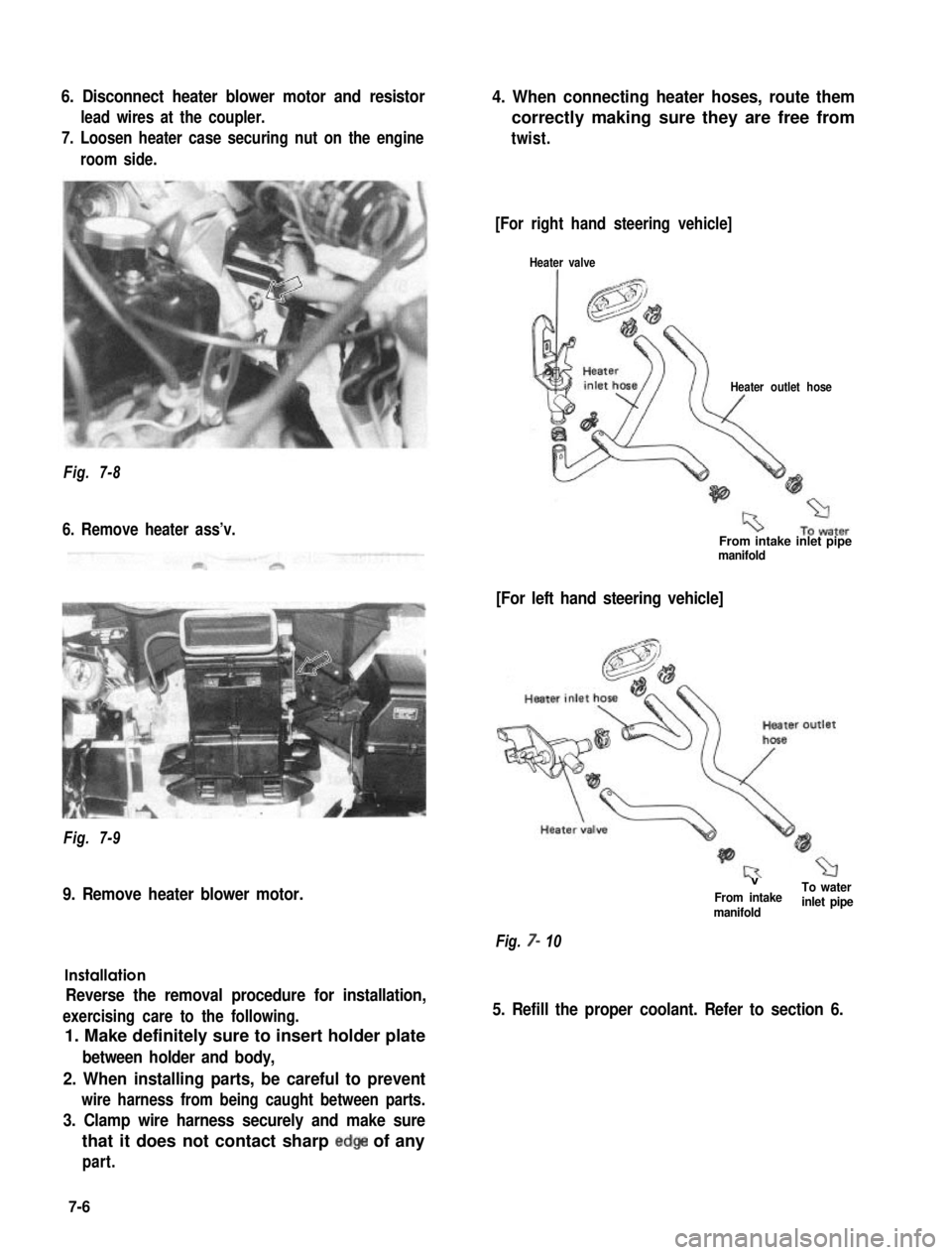
6. Disconnect heater blower motor and resistor
lead wires at the coupler.
7. Loosen heater case securing nut on the engine
room side.
4. When connecting heater hoses, route them
correctly making sure they are free from
twist.
Fig. 7-8
6. Remove heater ass’v.
Fig. 7-9
9. Remove heater blower motor.
Installation
Reverse the removal procedure for installation,
exercising care to the following.
1. Make definitely sure to insert holder plate
between holder and body,
2. When installing parts, be careful to prevent
wire harness from being caught between parts.
3. Clamp wire harness securely and make sure
that it does not contact sharp edge of any
part.
[For right hand steering vehicle]
Heater valve
Heater outlet hose
From intake inlet pipemanifold
[For left hand steering vehicle]
VTo waterFrom intakemanifoldinlet pipe
Fig. 7- 10
5. Refill the proper coolant. Refer to section 6.
7-6
Page 210 of 962
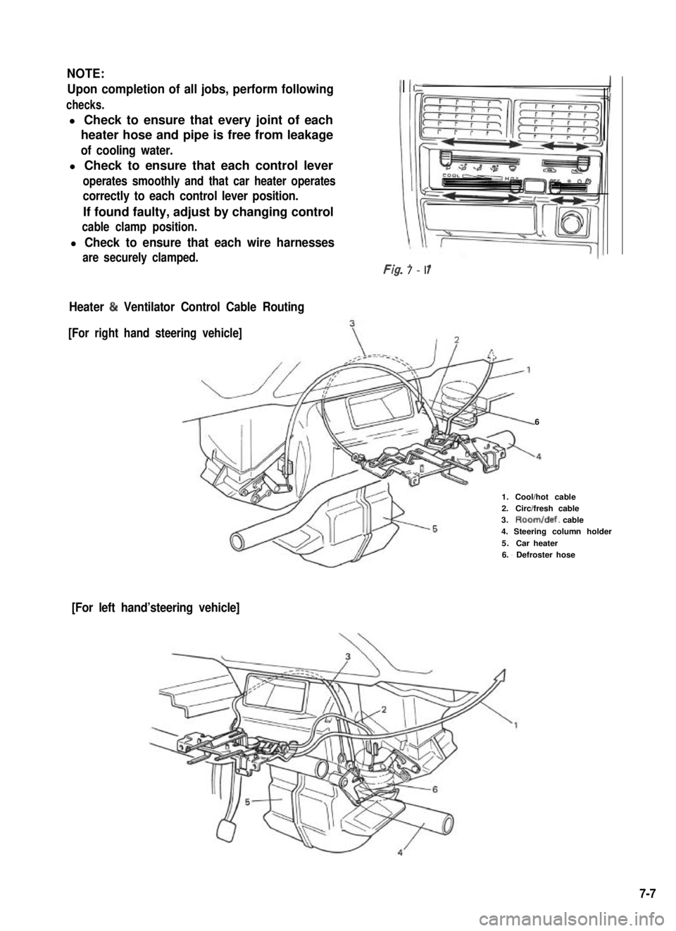
NOTE:
Upon completion of all jobs, perform following
checks.
l Check to ensure that every joint of each
heater hose and pipe is free from leakage
of cooling water.
l Check to ensure that each control lever
operates smoothly and that car heater operates
correctly to each control lever position.
If found faulty, adjust by changing control
cable clamp position.
l Check to ensure that each wire harnessesI
are securely clamped.Ff- -r/g. 7-l 1
Heater & Ventilator Control Cable Routing
[For right hand steering vehicle]
6
1.Cool/hot cable2.Circ/fresh cable3.Room/def. cable4. Steering column holder
5.Car heater6. I Defroster hose
[For left hand’steering vehicle]
7-7