relay SUZUKI GRAND VITARA 1999 2.G Workshop Manual
[x] Cancel search | Manufacturer: SUZUKI, Model Year: 1999, Model line: GRAND VITARA, Model: SUZUKI GRAND VITARA 1999 2.GPages: 656, PDF Size: 14.31 MB
Page 341 of 656
6E2-8 ENGINE AND EMISSION CONTROL SYSTEM (SEQUENTIAL MULTIPORT FUEL INJECTION FOR H27 ENGINE)
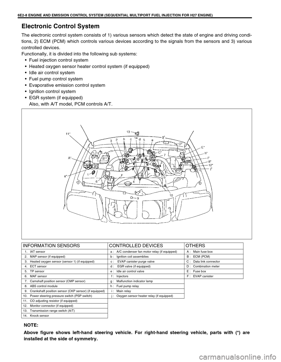
Electronic Control System
The electronic control system consists of 1) various sensors which detect the state of engine and driving condi-
tions, 2) ECM (PCM) which controls various devices according to the signals from the sensors and 3) various
controlled devices.
Functionally, it is divided into the following sub systems:
•Fuel injection control system
•Heated oxygen sensor heater control system (if equipped)
•Idle air control system
•Fuel pump control system
•Evaporative emission control system
•Ignition control system
•EGR system (if equipped)
Also, with A/T model, PCM controls A/T.
INFORMATION SENSORS CONTROLLED DEVICES OTHERS
1. IAT sensor a : A/C condenser fan motor relay (if equipped) A : Main fuse box
2. MAP sensor (if equipped) b : Ignition coil assemblies B : ECM (PCM)
3. Heated oxygen sensor (sensor 1) (if equipped) c : EVAP canister purge valve C : Data link connector
4. ECT sensor d : EGR valve (if equipped) D : Combination meter
5. TP sensor e : Idle air control valve E : Fuse box
6. MAF sensor f : Injectors F : EVAP canister
7. Camshaft position sensor (CMP sensor) g : Malfunction indicator lamp
8. ABS control module h : Fuel pump relay
9. Crankshaft position sensor (CKP sensor) (if equipped) i : Main relay
10. Power steering pressure switch (PSP switch) j : Oxygen sensor heater relay (if equipped)
11. CO adjusting resistor (if equipped)
12. Monitor connector (if equipped)
13. Transmission range switch (A/T)
14. Knock sensor
NOTE:
Above figure shows left-hand steering vehicle. For right-hand steering vehicle, parts with (*) are
installed at the side of symmetry.
Page 343 of 656
6E2-10 ENGINE AND EMISSION CONTROL SYSTEM (SEQUENTIAL MULTIPORT FUEL INJECTION FOR H27 ENGINE)
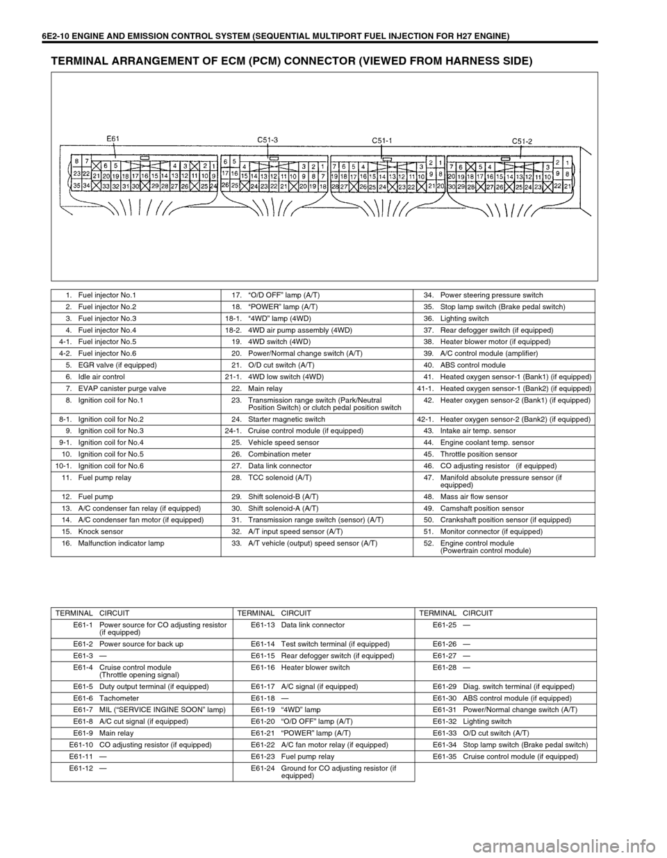
TERMINAL ARRANGEMENT OF ECM (PCM) CONNECTOR (VIEWED FROM HARNESS SIDE)
1. Fuel injector No.1 17.“O/D OFF” lamp (A/T) 34. Power steering pressure switch
2. Fuel injector No.2 18.“POWER” lamp (A/T) 35. Stop lamp switch (Brake pedal switch)
3. Fuel injector No.3 18-1.“4WD” lamp (4WD) 36. Lighting switch
4. Fuel injector No.4 18-2. 4WD air pump assembly (4WD) 37. Rear defogger switch (if equipped)
4-1. Fuel injector No.5 19. 4WD switch (4WD) 38. Heater blower motor (if equipped)
4-2. Fuel injector No.6 20. Power/Normal change switch (A/T) 39. A/C control module (amplifier)
5. EGR valve (if equipped) 21. O/D cut switch (A/T) 40. ABS control module
6. Idle air control 21-1. 4WD low switch (4WD) 41. Heated oxygen sensor-1 (Bank1) (if equipped)
7. EVAP canister purge valve 22. Main relay 41-1. Heated oxygen sensor-1 (Bank2) (if equipped)
8. Ignition coil for No.1 23. Transmission range switch (Park/Neutral
Position Switch) or clutch pedal position switch42. Heater oxygen sensor-2 (Bank1) (if equipped)
8-1. Ignition coil for No.2 24. Starter magnetic switch 42-1. Heater oxygen sensor-2 (Bank2) (if equipped)
9. Ignition coil for No.3 24-1. Cruise control module (if equipped) 43. Intake air temp. sensor
9-1. Ignition coil for No.4 25. Vehicle speed sensor 44. Engine coolant temp. sensor
10. Ignition coil for No.5 26. Combination meter 45. Throttle position sensor
10-1. Ignition coil for No.6 27. Data link connector 46. CO adjusting resistor (if equipped)
11. Fuel pump relay 28. TCC solenoid (A/T) 47. Manifold absolute pressure sensor (if
equipped)
12. Fuel pump 29. Shift solenoid-B (A/T) 48. Mass air flow sensor
13. A/C condenser fan relay (if equipped) 30. Shift solenoid-A (A/T) 49. Camshaft position sensor
14. A/C condenser fan motor (if equipped) 31. Transmission range switch (sensor) (A/T) 50. Crankshaft position sensor (if equipped)
15. Knock sensor 32. A/T input speed sensor (A/T) 51. Monitor connector (if equipped)
16. Malfunction indicator lamp 33. A/T vehicle (output) speed sensor (A/T) 52. Engine control module
(Powertrain control module)
TERMINAL CIRCUIT TERMINAL CIRCUIT TERMINAL CIRCUIT
E61-1 Power source for CO adjusting resistor
(if equipped)E61-13 Data link connector E61-25—
E61-2 Power source for back up E61-14 Test switch terminal (if equipped) E61-26—
E61-3—E61-15 Rear defogger switch (if equipped) E61-27—
E61-4 Cruise control module
(Throttle opening signal)E61-16 Heater blower switch E61-28—
E61-5 Duty output terminal (if equipped) E61-17 A/C signal (if equipped) E61-29 Diag. switch terminal (if equipped)
E61-6 Tachometer E61-18—E61-30 ABS control module (if equipped)
E61-7 MIL (“SERVICE INGINE SOON” lamp) E61-19“4WD” lamp E61-31 Power/Normal change switch (A/T)
E61-8 A/C cut signal (if equipped) E61-20“O/D OFF” lamp (A/T) E61-32 Lighting switch
E61-9 Main relay E61-21“POWER” lamp (A/T) E61-33 O/D cut switch (A/T)
E61-10 CO adjusting resistor (if equipped) E61-22 A/C fan motor relay (if equipped) E61-34 Stop lamp switch (Brake pedal switch)
E61-11—E61-23 Fuel pump relay E61-35 Cruise control module (if equipped)
E61-12—E61-24 Ground for CO adjusting resistor (if
equipped)
Page 345 of 656
6E2-12 ENGINE AND EMISSION CONTROL SYSTEM (SEQUENTIAL MULTIPORT FUEL INJECTION FOR H27 ENGINE)
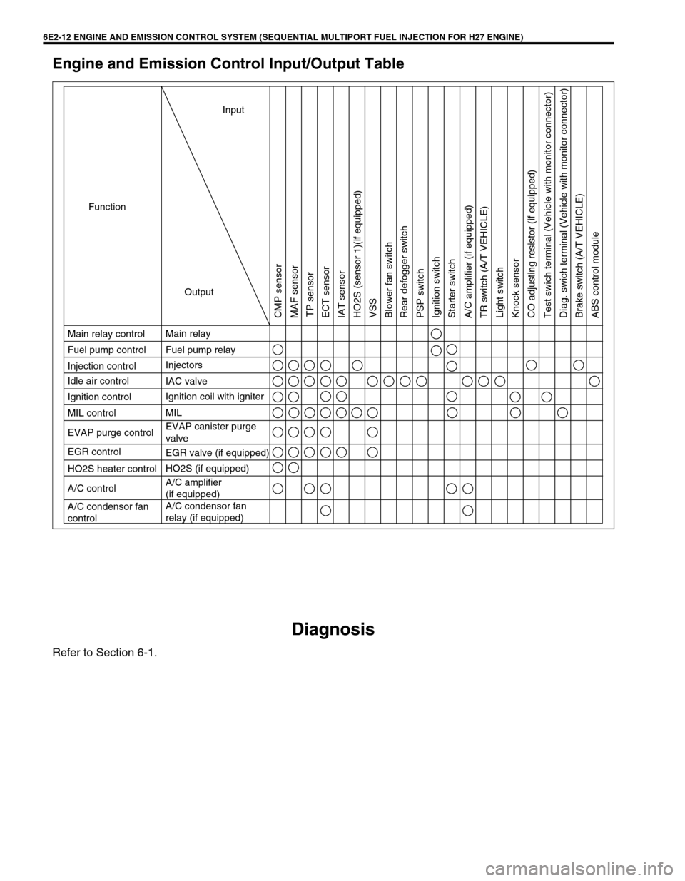
Engine and Emission Control Input/Output Table
Diagnosis
Refer to Section 6-1.
Ignition coil with igniter
HO2S heater control
Input
Output Function
Main relay control
Fuel pump control
Injection control
Ignition control
MIL control Idle air control
EVAP purge control
EGR control
A/C control
A/C condensor fan
controlMain relay
Fuel pump relay
Injectors
MIL
EVAP canister purge
valve IAC valve
EGR valve (if equipped)
HO2S (if equipped)
A/C amplifier
(if equipped)
A/C condensor fan
relay (if equipped)
CMP sensor
MAF sensor
TP sensor
ECT sensor
IAT sensor
HO2S (sensor 1)(if equipped)
VSS
Blower fan switch
Rear defogger switch
PSP switch
Ignition switch
Starter switch
A/C amplifier (if equipped)
TR switch (A/T VEHICLE)
Light switch
Knock sensor
CO adjusting resistor (if equipped)
Test swich terminal (Vehicle with monitor connector)
Diag. swich terminal (Vehicle with monitor connector)
Brake switch (A/T VEHICLE)
ABS control module
Page 361 of 656
6E2-28 ENGINE AND EMISSION CONTROL SYSTEM (SEQUENTIAL MULTIPORT FUEL INJECTION FOR H27 ENGINE)
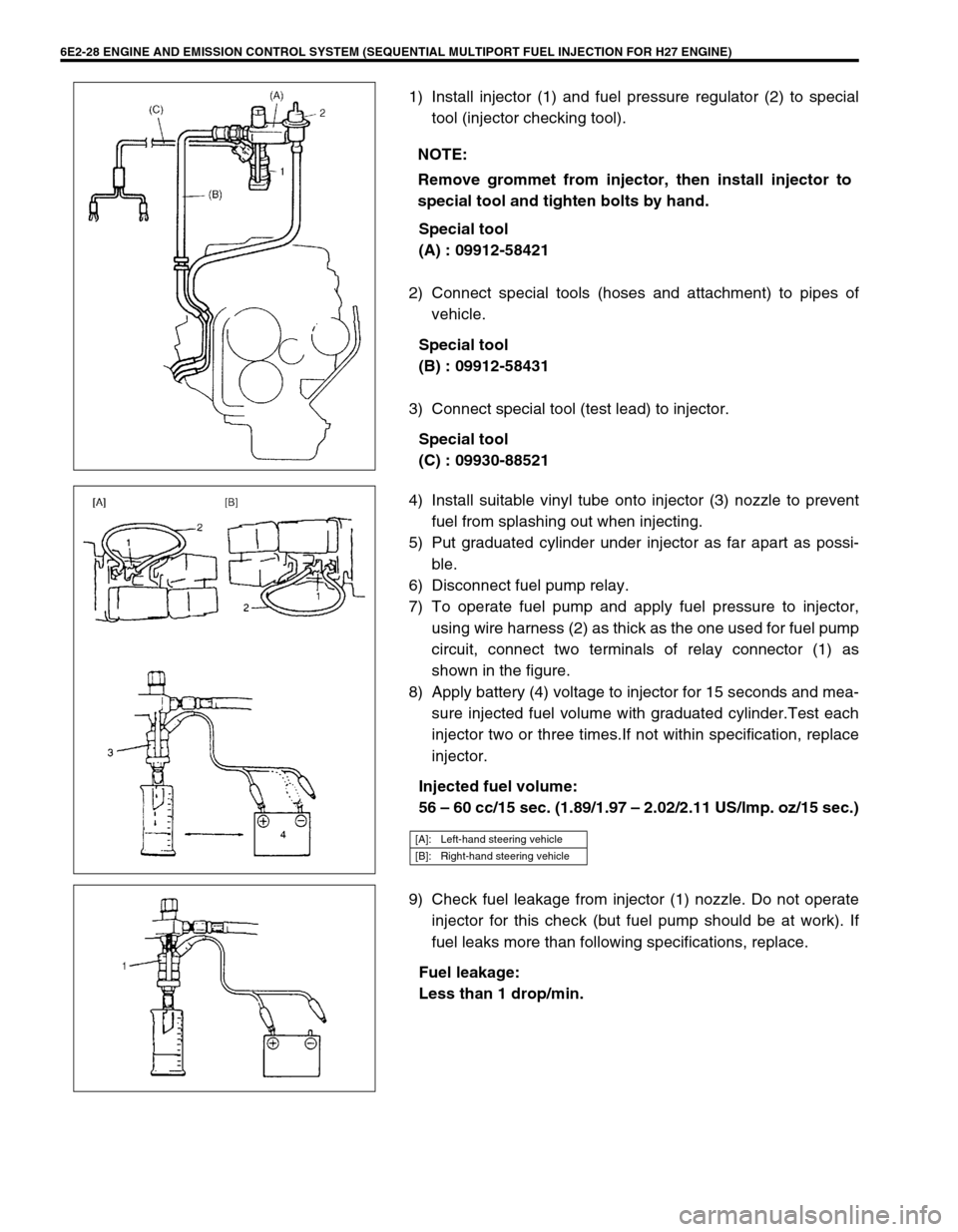
1) Install injector (1) and fuel pressure regulator (2) to special
tool (injector checking tool).
Special tool
(A) : 09912-58421
2) Connect special tools (hoses and attachment) to pipes of
vehicle.
Special tool
(B) : 09912-58431
3) Connect special tool (test lead) to injector.
Special tool
(C) : 09930-88521
4) Install suitable vinyl tube onto injector (3) nozzle to prevent
fuel from splashing out when injecting.
5) Put graduated cylinder under injector as far apart as possi-
ble.
6) Disconnect fuel pump relay.
7) To operate fuel pump and apply fuel pressure to injector,
using wire harness (2) as thick as the one used for fuel pump
circuit, connect two terminals of relay connector (1) as
shown in the figure.
8) Apply battery (4) voltage to injector for 15 seconds and mea-
sure injected fuel volume with graduated cylinder.Test each
injector two or three times.If not within specification, replace
injector.
Injected fuel volume:
56 – 60 cc/15 sec. (1.89/1.97 – 2.02/2.11 US/lmp. oz/15 sec.)
9) Check fuel leakage from injector (1) nozzle. Do not operate
injector for this check (but fuel pump should be at work). If
fuel leaks more than following specifications, replace.
Fuel leakage:
Less than 1 drop/min. NOTE:
Remove grommet from injector, then install injector to
special tool and tighten bolts by hand.
[A]: Left-hand steering vehicle
[B]: Right-hand steering vehicle
Page 374 of 656
ENGINE AND EMISSION CONTROL SYSTEM (SEQUENTIAL MULTIPORT FUEL INJECTION FOR H27 ENGINE) 6E2-41
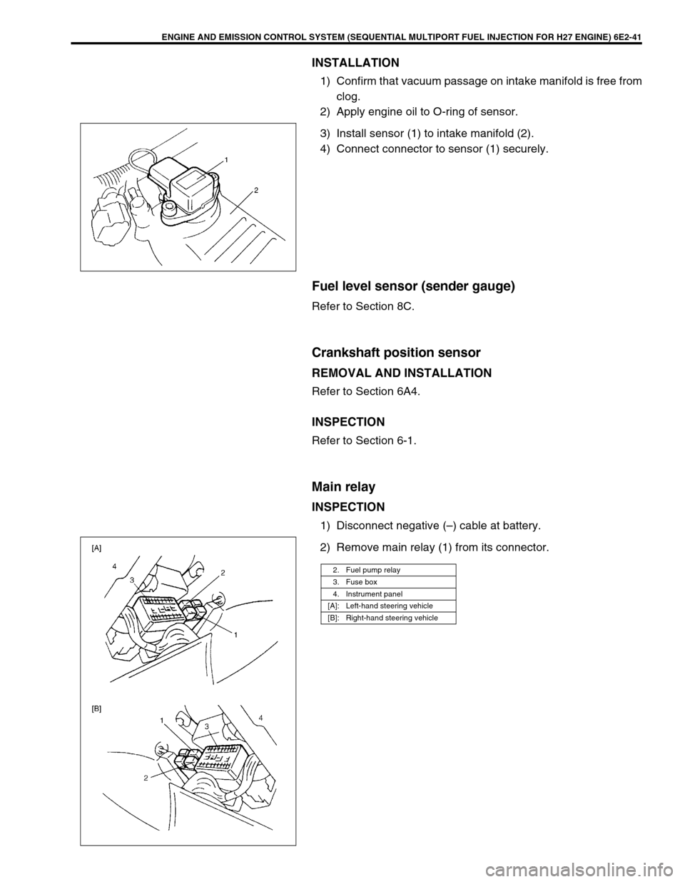
INSTALLATION
1) Confirm that vacuum passage on intake manifold is free from
clog.
2) Apply engine oil to O-ring of sensor.
3) Install sensor (1) to intake manifold (2).
4) Connect connector to sensor (1) securely.
Fuel level sensor (sender gauge)
Refer to Section 8C.
Crankshaft position sensor
REMOVAL AND INSTALLATION
Refer to Section 6A4.
INSPECTION
Refer to Section 6-1.
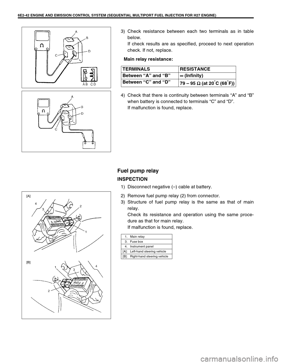
Main relay
INSPECTION
1) Disconnect negative (–) cable at battery.
2) Remove main relay (1) from its connector.
2. Fuel pump relay
3. Fuse box
4. Instrument panel
[A]: Left-hand steering vehicle
[B]: Right-hand steering vehicle
Page 375 of 656
6E2-42 ENGINE AND EMISSION CONTROL SYSTEM (SEQUENTIAL MULTIPORT FUEL INJECTION FOR H27 ENGINE)
3) Check resistance between each two terminals as in table
below.
If check results are as specified, proceed to next operation
check. If not, replace.
Main relay resistance:
4) Check that there is continuity between terminals “A” and “B”
when battery is connected to terminals “C” and “D”.
If malfunction is found, replace.
Fuel pump relay
INSPECTION
1) Disconnect negative (–) cable at battery.
2) Remove fuel pump relay (2) from connector.
3) Structure of fuel pump relay is the same as that of main
relay.
Check its resistance and operation using the same proce-
dure as that for main relay.
If malfunction is found, replace. TERMINALS RESISTANCE
Between “A” and “B”∞
∞∞ ∞ (Infinity)
Between “C” and “D”
79 – 95 Ω
ΩΩ Ω (at 20
°C (68°F))
1. Main relay
3. Fuse box
4. Instrument panel
[A]: Left-hand steering vehicle
[B]: Right-hand steering vehicle
Page 386 of 656
IGNITION SYSTEM (FOR H27 ENGINE) 6F2-3
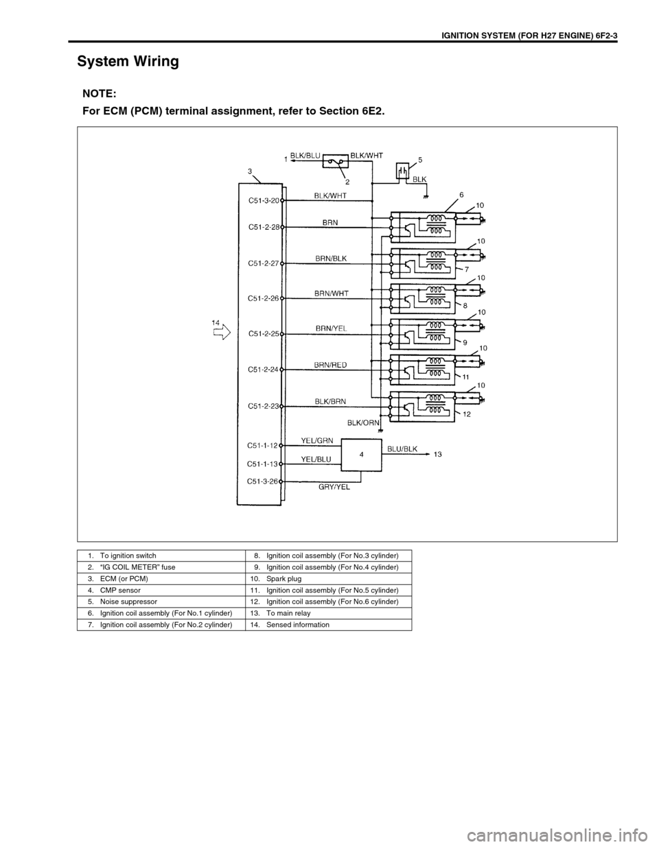
System Wiring
NOTE:
For ECM (PCM) terminal assignment, refer to Section 6E2.
1. To ignition switch 8. Ignition coil assembly (For No.3 cylinder)
2.“IG COIL METER” fuse 9. Ignition coil assembly (For No.4 cylinder)
3. ECM (or PCM) 10. Spark plug
4. CMP sensor 11. Ignition coil assembly (For No.5 cylinder)
5. Noise suppressor 12. Ignition coil assembly (For No.6 cylinder)
6. Ignition coil assembly (For No.1 cylinder) 13. To main relay
7. Ignition coil assembly (For No.2 cylinder) 14. Sensed information
Page 413 of 656
7B1-4 AUTOMATIC TRANSMISSION (4 A/T)
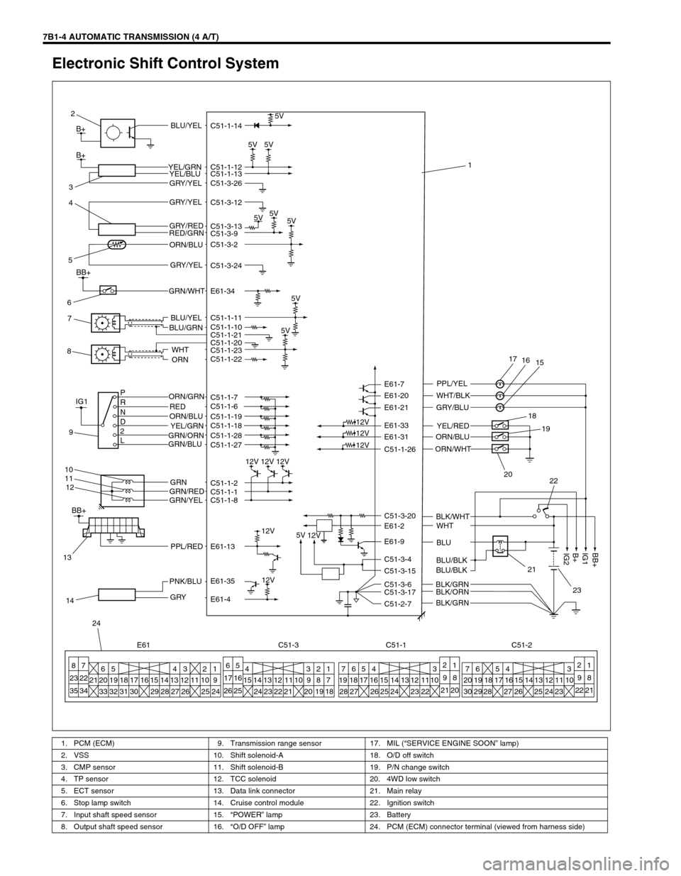
Electronic Shift Control System
1. PCM (ECM) 9. Transmission range sensor 17. MIL (“SERVICE ENGINE SOON” lamp)
2. VSS 10. Shift solenoid-A 18. O/D off switch
3. CMP sensor 11. Shift solenoid-B 19. P/N change switch
4. TP sensor 12. TCC solenoid 20. 4WD low switch
5. ECT sensor 13. Data link connector 21. Main relay
6. Stop lamp switch 14. Cruise control module 22. Ignition switch
7. Input shaft speed sensor 15.“POWER” lamp 23. Battery
8. Output shaft speed sensor 16.“O/D OFF” lamp 24. PCM (ECM) connector terminal (viewed from harness side)
5V
5V5V
5V5V
5V
5V 5V C51-1-14
C51-1-12
C51-1-13
C51-3-26
C51-3-12
C51-3-13
C51-3-9
C51-3-2
C51-3-24
C51-1-11
C51-1-10
C51-1-20 C51-1-21
C51-1-23
C51-1-22
C51-1-7
C51-1-6
C51-1-19
C51-1-18
C51-1-28
C51-1-27
C51-1-2
C51-1-1
C51-1-8
E61-13
E61-35
E61-4C51-1-26 E61-31 E61-33 E61-21 E61-20 E61-7
C51-3-20
E61-2
E61-9
C51-3-4
C51-3-15
C51-3-6
C51-3-17
C51-2-7
12V
12V 12V 12V
12V
12V
12V
12V
5V
12V
BLU/YEL
YEL/GRN
YEL/BLU
GRY/YEL
GRY/YEL
GRY/RED
RED/GRN
ORN/BLU
GRY/YEL
BLU/YEL
BLU/GRN
WHT
ORN
ORN/GRN
RED P
R
N
D
2
LORN/BLU
YEL/GRN
GRN/ORN
GRN/BLU
GRN
GRN/RED
GRN/YEL
PPL/RED
PNK/BLU
GRY
PPL/YEL
WHT/BLK
GRY/BLU
YEL/RED
ORN/BLU
WHT
BLU
BLU/BLK
BLU/BLK
BLK/GRN
BLK/ORN
BLK/GRNBLK/WHT ORN/WHT
8
7
23 22
35 346
20 21
335
19
3218
3117
3016 15
2914
284
13
273
12
26112
10
256
5
17 16
26 252
1
98
21 202
1
98
22 21 1
9
247
20
306
19
2918
27 17
2816 15
2614
25 5
13 4
12
24113
10
23 7
19
28654 3
18
2717 16
2615 14
2513
2412
2311
2210 4
15 14
2413
2312
2211 10 9 8 7
213
202
191
18
24
E61 C51-3 C51-1 C51-2 14
13
B+
B+
17
16
15
18
19
20
22
21
23
BB+
IG1
B+
IG2
1 2
3
4
5
7 6
8
IG1
9
10
11
12
BB+
E61-34 GRN/WHT
BB+
Page 418 of 656
AUTOMATIC TRANSMISSION (4 A/T) 7B1-9
Precaution in Diagnosing Trouble
•Don’t disconnect couplers from PCM (ECM), battery cable
from battery, PCM ground wire harness from engine or main
fuse before checking the diagnosis information (DTC, freeze
frame data, etc.) stored in PCM memory. Such disconnec-
tion will clear memorized information in PCM memory.
•Using SUZUKI scan tool or also generic scan tool for vehicle
without monitor connector, the diagnostic information stored
in PCM memory can be checked and cleared as well. Before
its use, be sure to read Operator’s (Instruction) Manual sup-
plied with it carefully to have good understanding of its func-
tions and usage.
•Priorities for diagnosing troubles
If two or more diagnostic trouble codes (DTCs) are stored,
proceed to the flow table of the DTC which was detected
earliest in the order and follow the instruction in that table.
If no instructions are given, troubleshoot diagnostic trouble
codes according to the following priorities.
–Diagnostic trouble codes (DTCs) other than DTC P0171/
P0172/P0174/P0175 (Fuel system too lean/too rich), DTC
P0300/P0301/P0302/P0303/P0304/P0305/P0306 (Misfire
detected) and DTC P0400 (EGR flow malfunction)
–DTC P0171/P0172/P0174/P0175 (Fuel system too lean/too
rich) and DTC P0400 (EGR flow malfunction)
–DTC P0300/P0301/P0302/P0303/P0304/P0305/P0306
(Misfire detected)
•Be sure to read “PRECAUTIONS FOR ELECTRICAL CIR-
CUIT SERVICE” in Section 0A before inspection and
observe what is written there.
•PCM replacement
When substituting a known-good PCM, check for following
conditions.
Neglecting this check may result in damage to a good PCM.
–All relays and actuators have resistance of specified value.
–MAF sensor, MDP sensor, TP sensor and fuel tank pres-
sure sensor are in good condition. Also, the power circuit of
these sensors is not shorted to the ground.
Page 510 of 656
BODY ELECTRICAL SYSTEM 8-1
6F1
6F2
6G
6H
6K
7A
8
6K
7C1
7D
7E
7F
8A
8D
8E
9
10
10A
10B
SECTION 8
BODY ELECTRICAL SYSTEM
Wiring System
(Harnesses, Connectors, Fuses, Relay, Switches, Grounds, System Circuit Diagram) .......... Section 8A
Lighting System .............................................................................................................................. Section 8B
Instrumententation and Driver Information .................................................................................. Section 8C
Windows, Mirrors, Security and Locks ......................................................................................... Section 8D
Immobilizer Control System............................................................................................................Section 8F
CONTENTS
General Description .......................................... 8-3
WARNING:
For vehicles equipped with Supplemental Restraint (Air Bag) System:
Service on and around the air bag system components or wiring must be performed only by an
authorized SUZUKI dealer. Refer to “Air Bag System Components and Wiring Location View” under
“General Description” in air bag system section in order to confirm whether you are performing ser-
vice on or near the air bag system components or wiring. Please observe all WARNINGS and “Ser-
vice Precautions” under “On-Vehicle Service” in air bag system section before performing service
on or around the air bag system components or wiring. Failure to follow WARNINGS could result in
unintentional activation of the system or could render the system inoperative. Either of these two
conditions may result in severe injury.
Technical service work must be started at least 90 seconds after the ignition switch is turned to the
“LOCK” position and the negative cable is disconnected from the battery. Otherwise, the system
may be activated by reserve energy in the Sensing and Diagnostic Module (SDM).
NOTE:
For the descriptions (items) not found in this section, refer to the same section of the Service Manual
mentioned in FOREWORD of this manual.