relay SUZUKI GRAND VITARA 1999 2.G Repair Manual
[x] Cancel search | Manufacturer: SUZUKI, Model Year: 1999, Model line: GRAND VITARA, Model: SUZUKI GRAND VITARA 1999 2.GPages: 656, PDF Size: 14.31 MB
Page 518 of 656
WINDOWS, MIRRORS, SECURITY AND LOCKS 8D-1
8D
SECTION 8D
WINDOWS, MIRRORS, SECURITY AND LOCKS
CONTENTS
General Description ....................................... 8D-2
Rear Wiper and Washer (If Equipped) ......... 8D-2
On-Vehicle Service......................................... 8D-3
Windshield Wipers ....................................... 8D-3
Front wiper and washer ............................ 8D-3Rear Window Wiper and Washer
(For Vehicle with Cruise Control System) .... 8D-4
Rear Wiper and Washer Switch ............... 8D-4
Rear Window Wiper and Washer
(For Vehicle without Cruise Control
System) ........................................................ 8D-4
Rear Wiper Intermittent Relay...................... 8D-4
WARNING:
For vehicles equipped with Supplemental Restraint (Air Bag) System:
Service on and around the air bag system components or wiring must be performed only by an
authorized SUZUKI dealer. Refer to “Air Bag System Components and Wiring Location View” under
“General Description” in air bag system section in order to confirm whether you are performing ser-
vice on or near the air bag system components or wiring. Please observe all WARNINGS and “Ser-
vice Precautions” under “On-Vehicle Service” in air bag system section before performing service
on or around the air bag system components or wiring. Failure to follow WARNINGS could result in
unintentional activation of the system or could render the system inoperative. Either of these two
conditions may result in severe injury.
Technical service work must be started at least 90 seconds after the ignition switch is turned to the
“LOCK” position and the negative cable is disconnected from the battery. Otherwise, the system
may be activated by reserve energy in the Sensing and Diagnostic Module (SDM).
NOTE:
For the descriptions (items) not found in this section, refer to the same section of the Service Manual
mentioned in FOREWORD of this manual.
Page 521 of 656
8D-4 WINDOWS, MIRRORS, SECURITY AND LOCKS
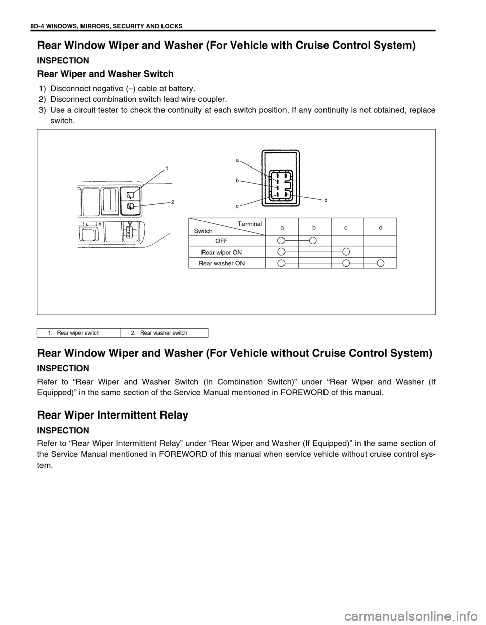
Rear Window Wiper and Washer (For Vehicle with Cruise Control System)
INSPECTION
Rear Wiper and Washer Switch
1) Disconnect negative (–) cable at battery.
2) Disconnect combination switch lead wire coupler.
3) Use a circuit tester to check the continuity at each switch position. If any continuity is not obtained, replace
switch.
Rear Window Wiper and Washer (For Vehicle without Cruise Control System)
INSPECTION
Refer to “Rear Wiper and Washer Switch (In Combination Switch)” under “Rear Wiper and Washer (If
Equipped)” in the same section of the Service Manual mentioned in FOREWORD of this manual.
Rear Wiper Intermittent Relay
INSPECTION
Refer to “Rear Wiper Intermittent Relay” under “Rear Wiper and Washer (If Equipped)” in the same section of
the Service Manual mentioned in FOREWORD of this manual when service vehicle without cruise control sys-
tem.
1. Rear wiper switch 2. Rear washer switch
Terminal
Switch
OFF
Rear wiper ON
Rear washer ONabc d
1
2
a
b
cd
Page 522 of 656
CRUISE CONTROL SYSTEM 8E-1
6F1
6F2
6G
6H
6K
7A
7A1
7B1
7C1
7D
7E
8E
8A
8B
8C
8D
8B
9
10
10A
10B
SECTION 8E
CRUISE CONTROL SYSTEM
CONTENTS
General Description ....................................... 8E-2
Cautions in Servicing ................................... 8E-2
Symbols and Marks ...................................... 8E-2
Abbreviations ............................................... 8E-2
Wiring Color Symbols ................................... 8E-2
Joint Connector ............................................ 8E-2
Fuse Box and Relay ..................................... 8E-2
Power Supply Diagram ................................ 8E-2
Cruise Control System ................................. 8E-3
Cruise control system circuit .................... 8E-3
Components and functions....................... 8E-4
Cancel Conditions .................................... 8E-5
Diagnosis ........................................................ 8E-5
Diagnosis Table ........................................... 8E-5
Note on System Circuit Inspection ............... 8E-7
Cruise Main Switch Indicator Lamp
Circuit Check ................................................ 8E-8
“Cruise” Indicator Lamp Circuit Check ......... 8E-9
Cruise Main Switch, Coast/Set,
Resume/Accel and Cancel Switches
Circuits Check ............................................ 8E-10
VSS Circuit Check ...................................... 8E-11
Stop Lamp Switch (with Pedal Position
Switch) Circuits Check ............................... 8E-12Transmission Range Switch Circuit Check 8E-13
Clutch Pedal Position Switch Circuit Check 8E-14
Throttle Valve Opening Signal Circuit
Check ......................................................... 8E-15
Overdrive and TCC off Command Signal
Circuit Check.............................................. 8E-16
Cruise Control Module Power and Ground
Circuits Check ............................................ 8E-16
Cruise Control Module and Its Circuit
Inspection................................................... 8E-17
Cruise Cable Play Inspection and
Adjustment ................................................. 8E-19
On-Vehicle Service ...................................... 8E-19
Cruise Main Switch .................................... 8E-19
Coast/Set, Resume/Accel and Cancel
Switches..................................................... 8E-20
Vehicle Speed Sensor (VSS) ..................... 8E-20
Transmission Range Switch ...................... 8E-20
Clutch Pedal Position (CPP) Switch .......... 8E-21
Stop Lamp Switch (with Pedal Position
Switch) ....................................................... 8E-22
Cruise Control Actuator Assembly
(with Control Module) ................................. 8E-23
Cruise Cable .............................................. 8E-24
WARNING:
For vehicles equipped with Supplemental Restraint (Air Bag) System:
Service on and around the air bag system components or wiring must be performed only by an
authorized SUZUKI dealer. Refer to “Air Bag System Components and Wiring Location View” under
“General Description” in air bag system section in order to confirm whether you are performing ser-
vice on or near the air bag system components or wiring. Please observe all WARNINGS and “Ser-
vice Precautions” under “On-Vehicle Service” in air bag system section before performing service
on or around the air bag system components or wiring. Failure to follow WARNINGS could result in
unintentional activation of the system or could render the system inoperative. Either of these two
conditions may result in severe injury.
Technical service work must be started at least 90 seconds after the ignition switch is turned to the
“LOCK” position and the negative cable is disconnected from the battery. Otherwise, the system
may be activated by reserve energy in the Sensing and Diagnostic Module (SDM).
Page 523 of 656
8E-2 CRUISE CONTROL SYSTEM
General Description
Cautions in Servicing
Refer to Section 8.
Symbols and Marks
Refer to Section 8A.
Abbreviations
Refer to Section 8A.
Wiring Color Symbols
Refer to Section 8.
Joint Connector
Refer to Section 8.
Fuse Box and Relay
Refer to Section 8A.
Power Supply Diagram
Refer to Section 8A.
Page 536 of 656
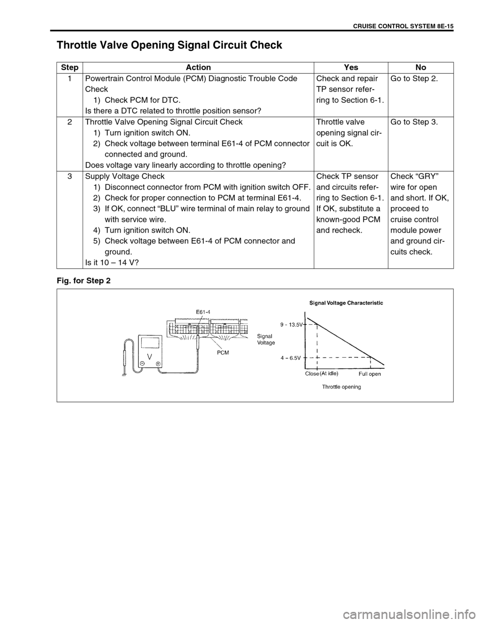
CRUISE CONTROL SYSTEM 8E-15
Throttle Valve Opening Signal Circuit Check
Fig. for Step 2Step Action Yes No
1 Powertrain Control Module (PCM) Diagnostic Trouble Code
Check
1) Check PCM for DTC.
Is there a DTC related to throttle position sensor?Check and repair
TP sensor refer-
ring to Section 6-1.Go to Step 2.
2 Throttle Valve Opening Signal Circuit Check
1) Turn ignition switch ON.
2) Check voltage between terminal E61-4 of PCM connector
connected and ground.
Does voltage vary linearly according to throttle opening?Throttle valve
opening signal cir-
cuit is OK.Go to Step 3.
3 Supply Voltage Check
1) Disconnect connector from PCM with ignition switch OFF.
2) Check for proper connection to PCM at terminal E61-4.
3) If OK, connect “BLU” wire terminal of main relay to ground
with service wire.
4) Turn ignition switch ON.
5) Check voltage between E61-4 of PCM connector and
ground.
Is it 10 – 14 V?Check TP sensor
and circuits refer-
ring to Section 6-1.
If OK, substitute a
known-good PCM
and recheck.Check “GRY”
wire for open
and short. If OK,
proceed to
cruise control
module power
and ground cir-
cuits check.