SUZUKI GRAND VITARA 2022 Owners Manual
Manufacturer: SUZUKI, Model Year: 2022, Model line: GRAND VITARA, Model: SUZUKI GRAND VITARA 2022Pages: 482, PDF Size: 21 MB
Page 161 of 482
3-21
OPERATING YOUR VEHICLE
54P00-01E
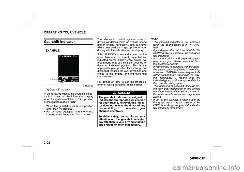
Gearshift indicator
61MM0A133
(1) Gearshift indicator
In the following cases, the gearshift indica-
tor is indicated on the information display
when the ignition switch is in “ON” position
or the ignition mode is “ON”.
• When the gearshift lever is in a position
other than “N” (Neutral).
• For vehicles equipped with the cruise
control, when the system is not in use.The electronic control system monitors
driving conditions (such as vehicle speed
and/or engine revolution), and it shows
which gear position is appropriate for your
driving with the indication on the display.
If the UP/DOWN arrow and a gear position
other than what is currently selected are
indicated on the display while driving, we
recommend that you shift the gear up or
down to indicated position. This is the
appropriate gear position for a driving con-
dition that reduces the over revolution and
stress to the engine, and improves fuel
consumption.
For details on how to use the transaxle,
refer to “Using transaxle” in this section.NOTE:
• The gearshift indicator is not indicated
when the gear position is in “N” (Neu-
tral).
• If you depress the clutch pedal while UP/
DOWN arrow is indicated, the indication
will disappear.
• In ordinary driving, UP arrow will disap-
pear when you release your foot from
the accelerator pedal.
If your vehicle is equipped with the adap-
tive cruise control and while it is working,
however, UP/DOWN arrow may be indi-
cated continuously depending on driv-
ing conditions. It means that the
indicated gear position is appropriate for
the current cruising speed.
• The indication of gearshift indicator tim-
ing may differ depending on the vehicle
condition and/or driving situation even in
the same vehicle speed and engine rev-
olution.
• If any of the electrical systems such as
the radar brake support system or the
ESP
® is working, the gearshift indicator
will disappear temporarily.
(1)
EXAMPLE
WA R N I N G
The gearshift indicator is designed to
indicate the appropriate gear position
for your driving, however, this indica-
tor does not relieve the driver of any
responsibility to operate gear
changes attentively.
To drive safely, do not focus your
attention on the gearshift indicator,
pay attention to your driving situation
and shift up or down if necessary.
Page 162 of 482
3-22
OPERATING YOUR VEHICLE
54P00-01E
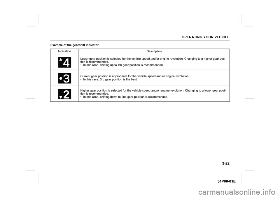
Example of the gearshift indicator
Indication Description
Lower gear position is selected for the vehicle speed and/or engine revolution. Changing to a higher gear posi-
tion is recommended.
• In this case, shifting up to 4th gear position is recommended.
Current gear position is appropriate for the vehicle speed and/or engine revolution.
• In this case, 3rd gear position is the best.
Higher gear position is selected for the vehicle speed and/or engine revolution. Changing to a lower gear posi-
tion is recommended.
• In this case, shifting down to 2nd gear position is recommended.
Page 163 of 482
3-23
OPERATING YOUR VEHICLE
54P00-01E
Four-mode 4WD system
(if equipped)
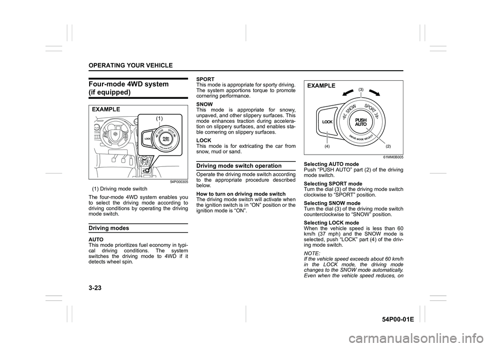
54P000305
(1) Driving mode switch
The four-mode 4WD system enables you
to select the driving mode according to
driving conditions by operating the driving
mode switch.
Driving modes
AUTO
This mode prioritizes fuel economy in typi-
cal driving conditions. The system
switches the driving mode to 4WD if it
detects wheel spin.SPORT
This mode is appropriate for sporty driving.
The system apportions torque to promote
cornering performance.
SNOW
This mode is appropriate for snowy,
unpaved, and other slippery surfaces. This
mode enhances traction during accelera-
tion on slippery surfaces, and enables sta-
ble cornering on slippery surfaces.
LOCK
This mode is for extricating the car from
snow, mud or sand.
Driving mode switch operation
Operate the driving mode switch according
to the appropriate procedure described
below.
How to turn on driving mode switch
The driving mode switch will activate when
the ignition switch is in “ON” position or the
ignition mode is “ON”.
61MM0B005
Selecting AUTO mode
Push “PUSH AUTO” part (2) of the driving
mode switch.
Selecting SPORT mode
Turn the dial (3) of the driving mode switch
clockwise to “SPORT” position.
Selecting SNOW mode
Turn the dial (3) of the driving mode switch
counterclockwise to “SNOW” position.
Selecting LOCK mode
When the vehicle speed is less than 60
km/h (37 mph) and the SNOW mode is
selected, push “LOCK” part (4) of the driv-
ing mode switch.
NOTE:
If the vehicle speed exceeds about 60 km/h
in the LOCK mode, the driving mode
changes to the SNOW mode automatically.
Even when the vehicle speed reduces, on
LOCKPUSH
AUTOSNOWSPORT
DRIVEMODESELECT
(1)
EXAMPLE
LOCKPUSH
AUTO
SNOWSPORT
DRIVEMODESELECT
(3)
(4)(2)
EXAMPLE
Page 164 of 482
3-24
OPERATING YOUR VEHICLE
54P00-01E
the other hand, the driving mode does not
return to the LOCK mode automatically. You
should select the LOCK mode according to
the driving conditions.
NOTE:
• The information display shows current
driving mode.
• When the ignition switch is turned to
“ON” position or the engine switch is
pressed to change the ignition mode to
“ON”, the AUTO mode is selected auto-
matically.
• The driving mode switch can be oper-
ated when the vehicle is either stopped
or moving.
• Check that the front wheels are in the
straight ahead position when operating
the driving mode switch.
• While making turns or accelerating and
decelerating, operating the driving mode
switch, turning the ignition switch to
“ACC” or “LOCK” position or pressing
the engine switch to change the ignition
mode to “ACC” or “LOCK” may cause a
shock, but this is not a system malfunc-
tion.
• When you operate your vehicle under
conditions that involve wheel spin, such
as driving off-road in the sand or water
or when a wheel has run off the road, the
difference in the amount of revolution
between front wheels and rear wheels
increases (wheels run idle). If this state
continues, the oil temperature of the
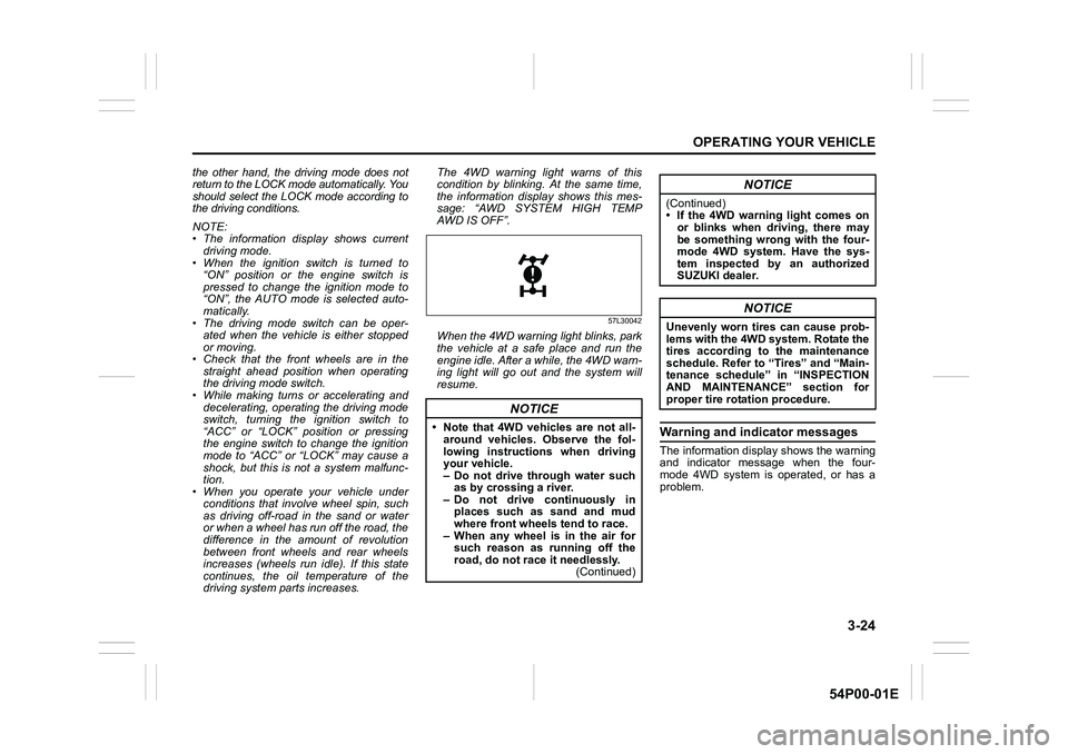
driving system parts increases. The 4WD warning light warns of this
condition by blinking. At the same time,
the information display shows this mes-
sage: “AWD SYSTEM HIGH TEMP
AWD IS OFF”.
57L30042
When the 4WD warning light blinks, park
the vehicle at a safe place and run the
engine idle. After a while, the 4WD warn-
ing light will go out and the system will
resume.
Warning and indicator messages
The information display shows the warning
and indicator message when the four-
mode 4WD system is operated, or has a
problem.
NOTICE
• Note that 4WD vehicles are not all-
around vehicles. Observe the fol-
lowing instructions when driving
your vehicle.
– Do not drive through water such
as by crossing a river.
– Do not drive continuously in
places such as sand and mud
where front wheels tend to race.
– When any wheel is in the air for
such reason as running off the
road, do not race it needlessly.
(Continued)
NOTICE
(Continued)
• If the 4WD warning light comes on
or blinks when driving, there may
be something wrong with the four-
mode 4WD system. Have the sys-
tem inspected by an authorized
SUZUKI dealer.
NOTICE
Unevenly worn tires can cause prob-
lems with the 4WD system. Rotate the
tires according to the maintenance
schedule. Refer to “Tires” and “Main-
tenance schedule” in “INSPECTION
AND MAINTENANCE” section for
proper tire rotation procedure.
Page 165 of 482
3-25
OPERATING YOUR VEHICLE
54P00-01E
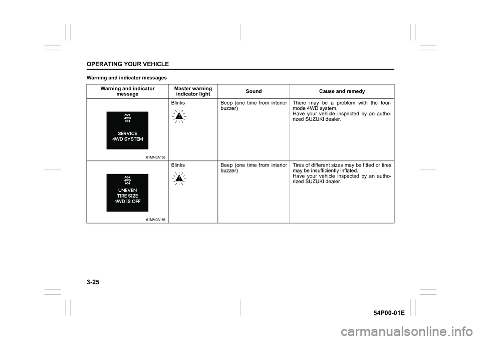
Warning and indicator messages
Warning and indicator
messageMaster warning
indicator lightSound Cause and remedy
61MM0A185
Blinks Beep (one time from interior
buzzer) There may be a problem with the four-
mode 4WD system.
Have your vehicle inspected by an autho-
rized SUZUKI dealer.
61MM0A186
Blinks Beep (one time from interior
buzzer) Tires of different sizes may be fitted or tires
may be insufficiently inflated.
Have your vehicle inspected by an autho-
rized SUZUKI dealer.
Page 166 of 482
3-26
OPERATING YOUR VEHICLE
54P00-01E
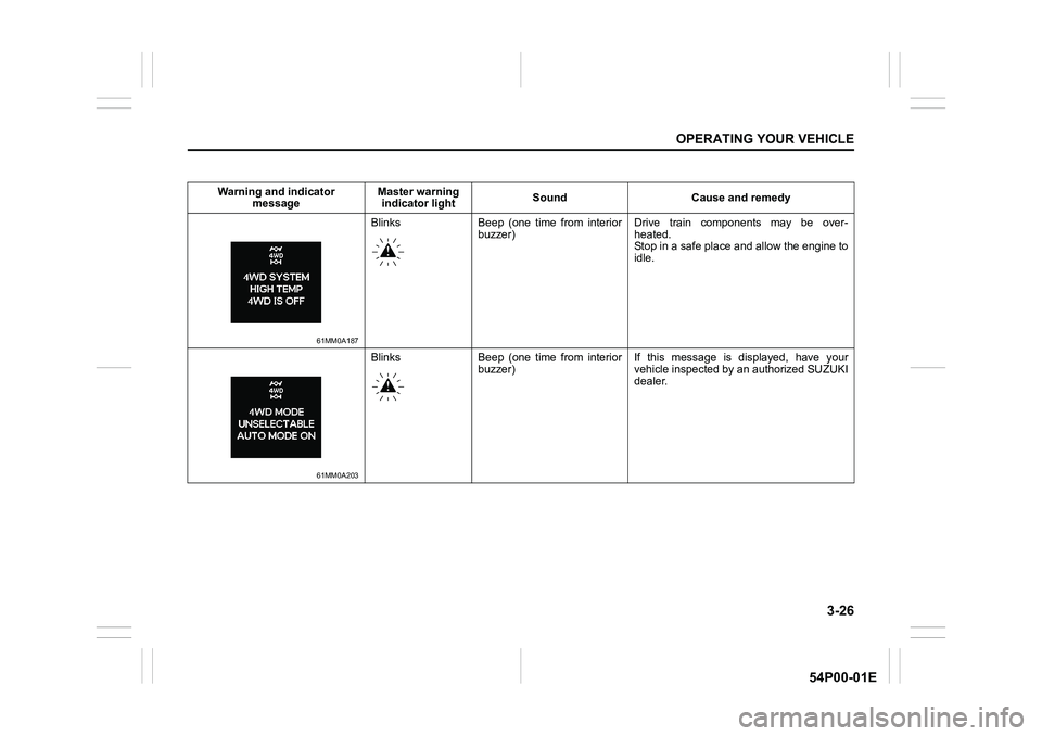
Warning and indicator
messageMaster warning
indicator lightSound Cause and remedy
61MM0A187
Blinks Beep (one time from interior
buzzer) Drive train components may be over-
heated.
Stop in a safe place and allow the engine to
idle.
61MM0A203
Blinks Beep (one time from interior
buzzer) If this message is displayed, have your
vehicle inspected by an authorized SUZUKI
dealer.
Page 167 of 482
3-27
OPERATING YOUR VEHICLE
54P00-01E
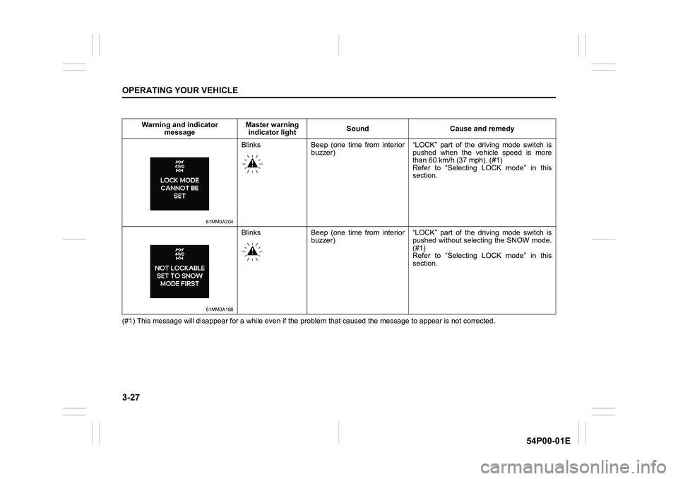
(#1) This message will disappear for a while even if the problem that caused the message to appear is not corrected. Warning and indicator
messageMaster warning
indicator lightSound Cause and remedy
61MM0A204
Blinks Beep (one time from interior
buzzer) “LOCK” part of the driving mode switch is
pushed when the vehicle speed is more
than 60 km/h (37 mph). (#1)
Refer to “Selecting LOCK mode” in this
section.
61MM0A188
Blinks Beep (one time from interior
buzzer) “LOCK” part of the driving mode switch is
pushed without selecting the SNOW mode.
(#1)
Refer to “Selecting LOCK mode” in this
section.
Page 168 of 482
3-28
OPERATING YOUR VEHICLE
54P00-01E
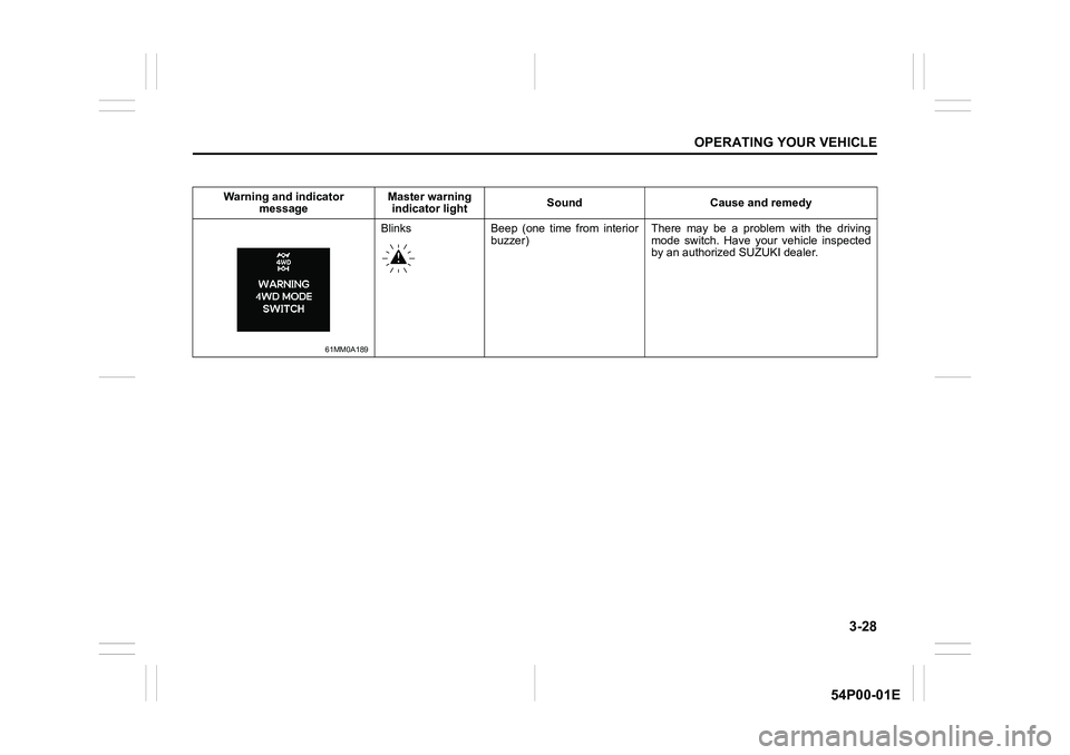
Warning and indicator
messageMaster warning
indicator lightSound Cause and remedy
61MM0A189
Blinks Beep (one time from interior
buzzer) There may be a problem with the driving
mode switch. Have your vehicle inspected
by an authorized SUZUKI dealer.
Page 169 of 482
3-29
OPERATING YOUR VEHICLE
54P00-01E
ENG A-STOP system
(engine auto stop start
system) (if equipped)
The ENG A-STOP system (engine auto
stop start system) automatically stops and
restarts the engine without operating the
ignition switch or the engine switch when
the vehicle is stopped, such as at a traffic
signal or in a traffic jam, to reduce exhaust
gases and fuel consumption.
• When the vehicle will be stopped for a
long time or when you will leave the
vehicle unattended, turn the ignition
switch to “LOCK” position or press the
engine switch to stop the engine.
NOTE:
If your vehicle is equipped with the auto air
conditioning system, you can change the
auto engine stop condition via the informa-
tion display. Refer to “Information display”
in “BEFORE DRIVING” section.
72M2042
The ENG A-STOP system is automatically
activated when the ignition switch is turned
to “ON” position or the engine switch is
pressed to change the ignition mode to
“ON”.
The system activation also requires the fol-
lowing conditions:
• Driver’s seat belt is fastened.
• Driver’s door is closed.
• Engine hood is closed.
For more details, refer to the explanation
below.
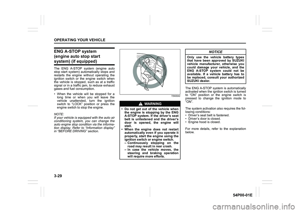
WA R N I N G
• Do not get out of the vehicle when
the engine is stopping by the ENG
A-STOP system. If the driver’s seat
belt is unfastened and the driver’s
door is opened, the engine will
stall.
• When the engine does not restart
automatically even if you operate it
properly, start the engine using the
ignition switch or engine switch.
– Continuously stopping on the
road may result in rear crash.
– In case the vehicle moves, the
steering and braking operation
will require more efforts.
NOTICE
Only use the vehicle battery types
that have been approved by SUZUKI
vehicle manufacturer, otherwise you
could damage your vehicle, and the
ENG A-STOP system could not be
available. If a vehicle battery has to
be replaced, consult your authorized
SUZUKI dealer.
Page 170 of 482
3-30
OPERATING YOUR VEHICLE
54P00-01E
Automatically stopping engine
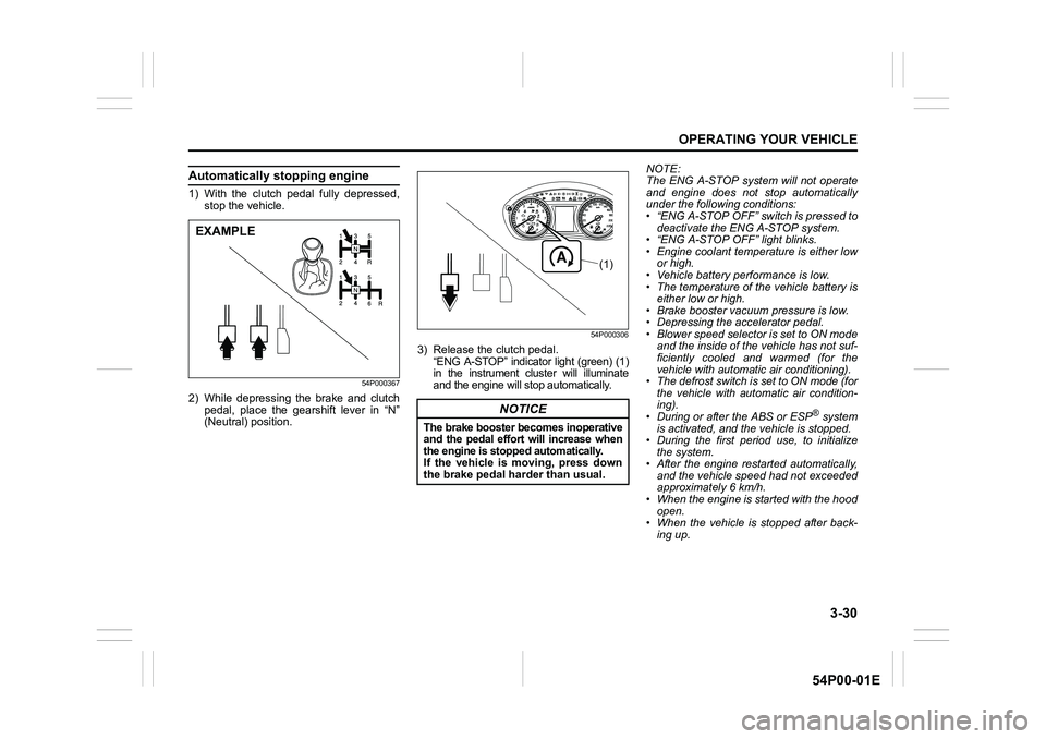
1) With the clutch pedal fully depressed,
stop the vehicle.
54P000367
2) While depressing the brake and clutch
pedal, place the gearshift lever in “N”
(Neutral) position.
54P000306
3) Release the clutch pedal.
“ENG A-STOP” indicator light (green) (1)
in the instrument cluster will illuminate
and the engine will stop automatically.NOTE:
The ENG A-STOP system will not operate
and engine does not stop automatically
under the following conditions:
• “ENG A-STOP OFF” switch is pressed to
deactivate the ENG A-STOP system.
• “ENG A-STOP OFF” light blinks.
• Engine coolant temperature is either low
or high.
• Vehicle battery performance is low.
• The temperature of the vehicle battery is
either low or high.
• Brake booster vacuum pressure is low.
• Depressing the accelerator pedal.
• Blower speed selector is set to ON mode
and the inside of the vehicle has not suf-
ficiently cooled and warmed (for the
vehicle with automatic air conditioning).
• The defrost switch is set to ON mode (for
the vehicle with automatic air condition-
ing).
• During or after the ABS or ESP
® system
is activated, and the vehicle is stopped.
• During the first period use, to initialize
the system.
• After the engine restarted automatically,
and the vehicle speed had not exceeded
approximately 6 km/h.
• When the engine is started with the hood
open.
• When the vehicle is stopped after back-
ing up.
EXAMPLE
NOTICE
The brake booster becomes inoperative
and the pedal effort will increase when
the engine is stopped automatically.
If the vehicle is moving, press down
the brake pedal harder than usual.
(1)