water pump SUZUKI JIMNY 2005 3.G Service Owner's Manual
[x] Cancel search | Manufacturer: SUZUKI, Model Year: 2005, Model line: JIMNY, Model: SUZUKI JIMNY 2005 3.GPages: 687, PDF Size: 13.38 MB
Page 592 of 687

Downloaded from www.Manualslib.com manuals search engine ENGINE COOLING 6B-15
Water Pump
COMPONENTS
REMOVAL
1) Drain cooling system.
Refer to Step 6) of “Cooling System Flush and Refill” in this
section.
2) Remove the radiator shroud.
3) Remove radiator referring to “Radiator” in this section.
4) Loosen water pump drive belt tension.
Then remove water pump pulley (2) with fan clutch (3) and
pump drive belt.
5) Remove water pump assembly (1).
1. Water pump 4. Radiator cooling fan 7. Radiator cooling fan mounting bolt
2. Water pump pulley 5. Water pump mounting bolts Tightening Torque
3. Radiator cooling fan clutch 6. Water pump pulley and fan clutch mounting nuts
1. Drain plug
Page 593 of 687
Downloaded from www.Manualslib.com manuals search engine 6B-16 ENGINE COOLING
INSPECTION
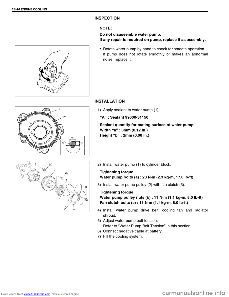
Rotate water pump by hand to check for smooth operation.
If pump does not rotate smoothly or makes an abnormal
noise, replace it.
INSTALLATION
1) Apply sealant to water pump (1).
“A” : Sealant 99000-31150
Sealant quantity for mating surface of water pump
Width “a” : 3mm (0.12 in.)
Height “b” : 2mm (0.08 in.)
2) Install water pump (1) to cylinder block.
Tightening torque
Water pump bolts (a) : 23 N·m (2.3 kg-m, 17.0 lb-ft)
3) Install water pump pulley (2) with fan clutch (3).
Tightening torque
Water pump pulley nuts (b) : 11 N·m (1.1 kg-m, 8.0 lb-ft)
Fan clutch bolts (c) : 11 N·m (1.1 kg-m, 8.0 lb-ft)
4) Install water pump drive belt, cooling fan and radiator
shroud.
5) Adjust water pump belt tension.
Refer to “Water Pump Belt Tension” in this section.
6) Connect negative cable at battery.
7) Fill the cooling system.NOTE:
Do not disassemble water pump.
If any repair is required on pump, replace it as assembly.
Page 594 of 687

Downloaded from www.Manualslib.com manuals search engine ENGINE COOLING 6B-17
Required Service Material
Tightening Torque Specification
MaterialRecommended SUZUKI product
(Part Number)Use
Ethylene glycol base
coolant (Anti-freeze /
Anti-corrosion coolant)–Additive to engine cooling system for improving
cooling efficiency and for protection against
rusting.
SealantSUZUKI BOND NO.1207C
(99000 – 31150)To apply to water pump mating surface.
Fastening partTightening torque
Nm kg-m lb-ft
Water pump bolt 23 2.3 17.0
Thermostat cap bolt 11 1.1 8.0
Thermostat case bolt 25 2.5 18.0
Fun clutch bolt 11 1.1 8.0
Page 601 of 687
Downloaded from www.Manualslib.com manuals search engine 6C-6 ENGINE FUEL
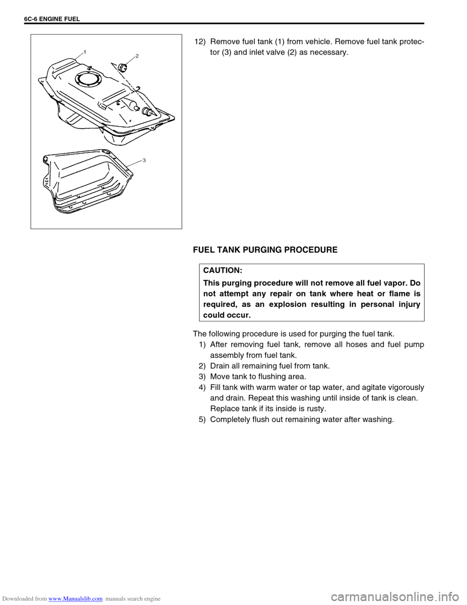
12) Remove fuel tank (1) from vehicle. Remove fuel tank protec-
tor (3) and inlet valve (2) as necessary.
FUEL TANK PURGING PROCEDURE
The following procedure is used for purging the fuel tank.
1) After removing fuel tank, remove all hoses and fuel pump
assembly from fuel tank.
2) Drain all remaining fuel from tank.
3) Move tank to flushing area.
4) Fill tank with warm water or tap water, and agitate vigorously
and drain. Repeat this washing until inside of tank is clean.
Replace tank if its inside is rusty.
5) Completely flush out remaining water after washing.
CAUTION:
This purging procedure will not remove all fuel vapor. Do
not attempt any repair on tank where heat or flame is
required, as an explosion resulting in personal injury
could occur.
Page 640 of 687
Downloaded from www.Manualslib.com manuals search engine ENGINE AND EMISSION CONTROL SYSTEM 6E-35
Crankshaft position sensor
INSPECTION
Check crankshaft position sensor referring to step 2 and 6 of
“DTC P0335 (No.23) Flow Table” in Section 6. If malfunction is
found, replace.
REMOVAL
1) Disconnect negative cable at battery.
2) Remove generator drive belt, loosen pivot bolt and move
generator outward.
3) Disconnect connector from crankshaft position sensor.
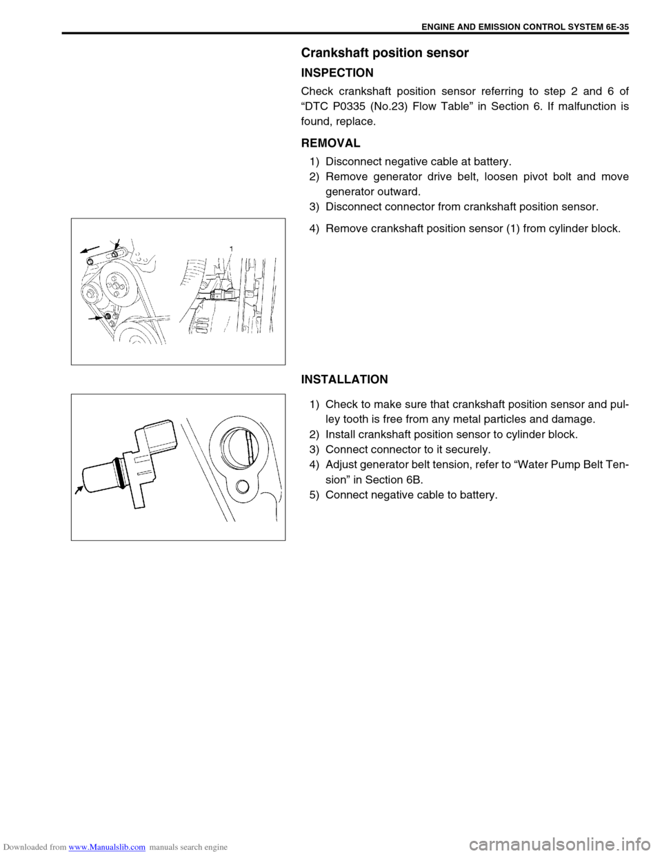
4) Remove crankshaft position sensor (1) from cylinder block.
INSTALLATION
1) Check to make sure that crankshaft position sensor and pul-
ley tooth is free from any metal particles and damage.
2) Install crankshaft position sensor to cylinder block.
3) Connect connector to it securely.
4) Adjust generator belt tension, refer to “Water Pump Belt Ten-
sion” in Section 6B.
5) Connect negative cable to battery.
Page 678 of 687
Downloaded from www.Manualslib.com manuals search engine CHARGING SYSTEM 6H-11
Dismounting
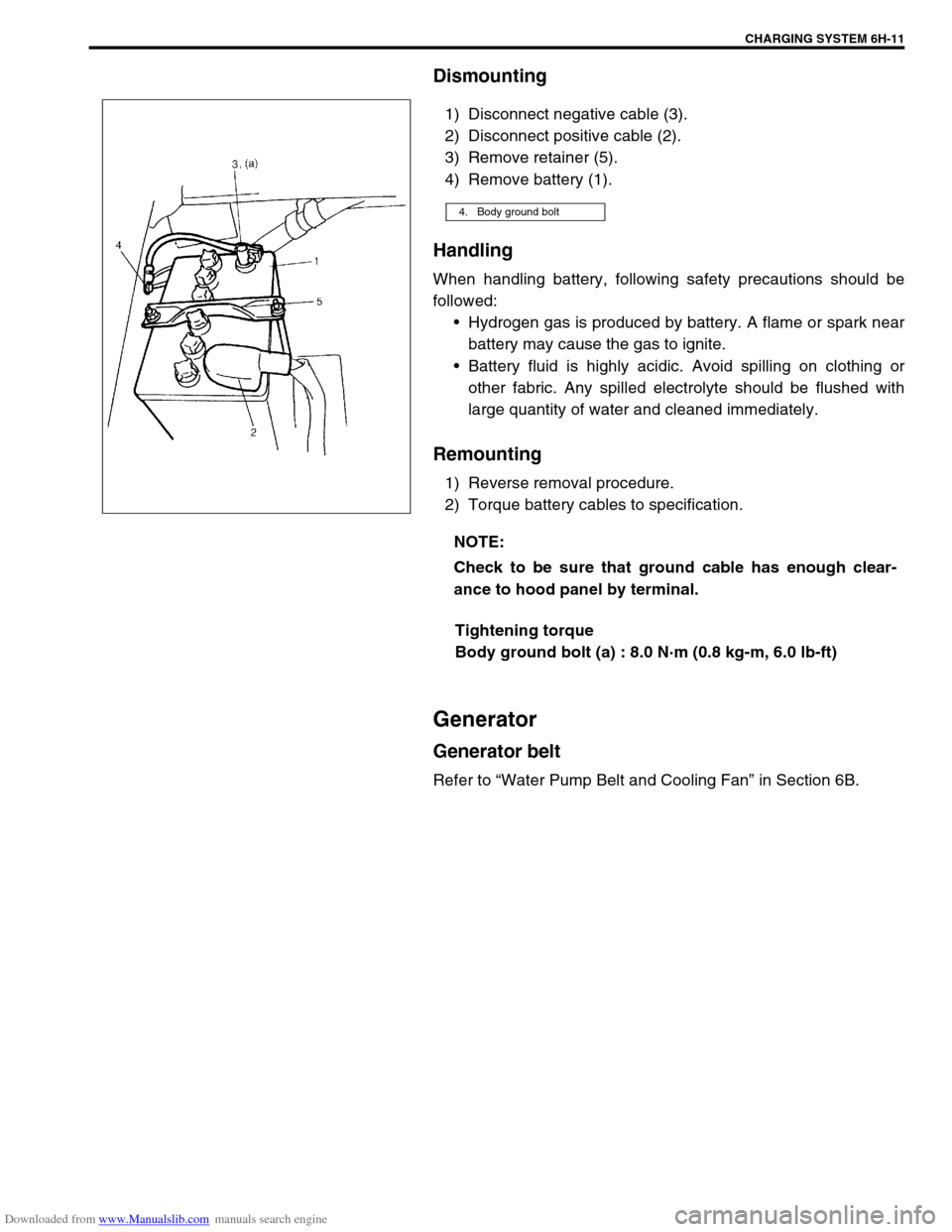
1) Disconnect negative cable (3).
2) Disconnect positive cable (2).
3) Remove retainer (5).
4) Remove battery (1).
Handling
When handling battery, following safety precautions should be
followed:
Hydrogen gas is produced by battery. A flame or spark near
battery may cause the gas to ignite.
Battery fluid is highly acidic. Avoid spilling on clothing or
other fabric. Any spilled electrolyte should be flushed with
large quantity of water and cleaned immediately.
Remounting
1) Reverse removal procedure.
2) Torque battery cables to specification.
Tightening torque
Body ground bolt (a) : 8.0 N·m (0.8 kg-m, 6.0 lb-ft)
Generator
Generator belt
Refer to “Water Pump Belt and Cooling Fan” in Section 6B.
4. Body ground bolt
NOTE:
Check to be sure that ground cable has enough clear-
ance to hood panel by terminal.
Page 679 of 687

Downloaded from www.Manualslib.com manuals search engine 6H-12 CHARGING SYSTEM
Unit Repair Overhaul
Generator
Dismounting
1) Disconnect negative (–) cable (2) at battery (1).
2) Remove bolts (2) and then canister (1) together with its
bracket.
3) Disconnect “B” terminal wire (3) and coupler (2) from gener-
ator (1).
4) Remove generator belt. Refer to “Water Pump Belt and
Cooling Fan” in Section 6B.
5) Remove generator.
1. Generator adjusting bolt
2. Generator pivot bolt
3.“B” terminal
Page 680 of 687
Downloaded from www.Manualslib.com manuals search engine CHARGING SYSTEM 6H-13
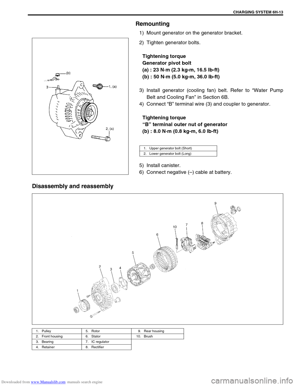
Remounting
1) Mount generator on the generator bracket.
2) Tighten generator bolts.
Tightening torque
Generator pivot bolt
(a) : 23 N·m (2.3 kg-m, 16.5 lb-ft)
(b) : 50 N·m (5.0 kg-m, 36.0 lb-ft)
3) Install generator (cooling fan) belt. Refer to “Water Pump
Belt and Cooling Fan” in Section 6B.
4) Connect “B” terminal wire (3) and coupler to generator.
Tightening torque
“B” terminal outer nut of generator
(b) : 8.0 N·m (0.8 kg-m, 6.0 lb-ft)
5) Install canister.
6) Connect negative (–) cable at battery.
Disassembly and reassembly
1. Upper generator bolt (Short)
2. Lower generator bolt (Long)
1. Pulley 5. Rotor 9. Rear housing
2. Front housing 6. Stator 10. Brush
3. Bearing 7. IC regulator
4. Retainer 8. Rectifier