lock SUZUKI JIMNY 2005 3.G Service Repair Manual
[x] Cancel search | Manufacturer: SUZUKI, Model Year: 2005, Model line: JIMNY, Model: SUZUKI JIMNY 2005 3.GPages: 687, PDF Size: 13.38 MB
Page 205 of 687
Downloaded from www.Manualslib.com manuals search engine 3D-32 FRONT SUSPENSION
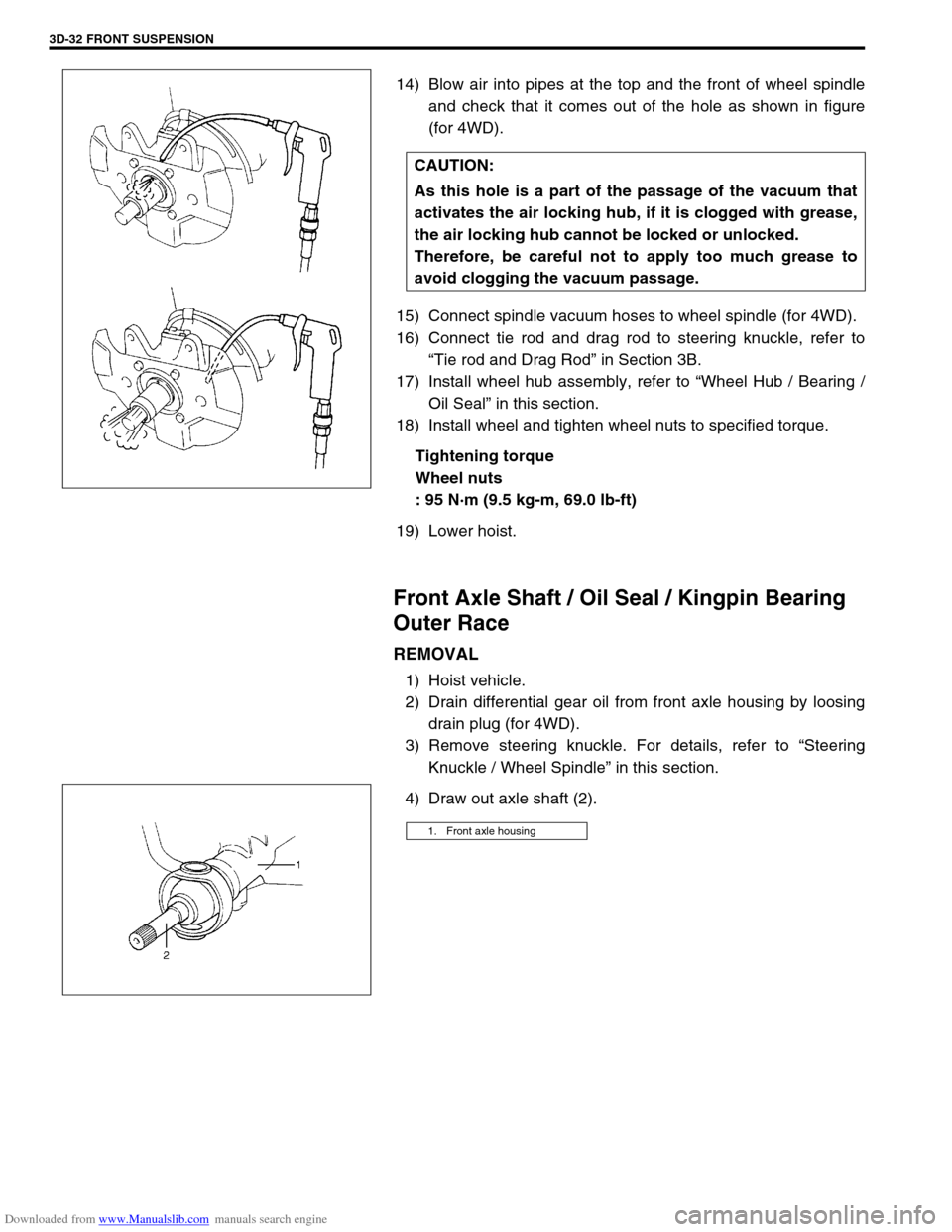
14) Blow air into pipes at the top and the front of wheel spindle
and check that it comes out of the hole as shown in figure
(for 4WD).
15) Connect spindle vacuum hoses to wheel spindle (for 4WD).
16) Connect tie rod and drag rod to steering knuckle, refer to
“Tie rod and Drag Rod” in Section 3B.
17) Install wheel hub assembly, refer to “Wheel Hub / Bearing /
Oil Seal” in this section.
18) Install wheel and tighten wheel nuts to specified torque.
Tightening torque
Wheel nuts
: 95 N·m (9.5 kg-m, 69.0 lb-ft)
19) Lower hoist.
Front Axle Shaft / Oil Seal / Kingpin Bearing
Outer Race
REMOVAL
1) Hoist vehicle.
2) Drain differential gear oil from front axle housing by loosing
drain plug (for 4WD).
3) Remove steering knuckle. For details, refer to “Steering
Knuckle / Wheel Spindle” in this section.
4) Draw out axle shaft (2).CAUTION:
As this hole is a part of the passage of the vacuum that
activates the air locking hub, if it is clogged with grease,
the air locking hub cannot be locked or unlocked.
Therefore, be careful not to apply too much grease to
avoid clogging the vacuum passage.
1. Front axle housing
Page 209 of 687

Downloaded from www.Manualslib.com manuals search engine 3D-36 FRONT SUSPENSION
Leading Arm / Bushing
REMOVAL
1) Hoist vehicle.
2) Remove air locking hub vacuum pipe clamp bolts (2) (for
4WD).
3) Support front axle housing by using floor jack.
4) Remove shock absorber lower mounting bolt, refer to “Front
Shock Absorber” in this section.
5) Remove mounting bolts and leading arm (1).
6) Remove bushings by using hydraulic press and special
tools.
Special tool
(A) : 09924-74510
(B) : 09951-16030
(C) : 09951-26010
1. Leading arm (right side)
Page 210 of 687

Downloaded from www.Manualslib.com manuals search engine FRONT SUSPENSION 3D-37
INSTALLATION
1) Install bushings (1) by using hydraulic press and special
tools, noting the following point.
Install bushings (1) so that either face of bushing are aligned
with housing edge of leading arm (2), also the length
between the aligned side end of bushing and leading arm (2)
are within specification below.
Special tool
(A) : 09913-85210
(B) : 09951-26010
Specification for leading arm bushing protrusion
“a” : 8.5 – 10.5 mm (0.33 – 0.41 in.)
“b” : 6.0 – 9.0 mm (0.24 – 0.35 in.)
2) Install leading arm (1) to vehicle body and axle housing,
referring to figure for proper installing direction of bolts.
Nuts should not be tightened.
3) Install shock absorber lower mounting bolt, refer to “Front
Shock Absorber” in this section.
4) Install air locking hub vacuum pipe clamp bolts and tighten
them to specified torque (for 4WD).
Tightening torque
Vacuum pipe clamp bolts
(b) : 5.5 N·m (0.55 kg-m, 4.0 lb-ft)
5) Lower hoist and with vehicle in non-loaded condition, tighten
nuts of leading arm to specified torque.
Tightening torque
Leading arm nuts
(a) : 90 N·m (9.0 kg-m, 65.0 lb-ft)
2. Vacuum hose
3. Body outside
[A] : Front
[B] : Rear
Page 211 of 687
Downloaded from www.Manualslib.com manuals search engine 3D-38 FRONT SUSPENSION
Front Axle Housing
REMOVAL
1) Hoist vehicle.
2) Remove front wheels.
3) Drain front differential gear oil (for 4WD).
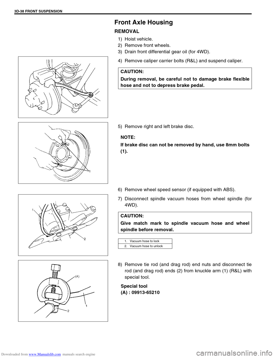
4) Remove caliper carrier bolts (R&L) and suspend caliper.
5) Remove right and left brake disc.
6) Remove wheel speed sensor (if equipped with ABS).
7) Disconnect spindle vacuum hoses from wheel spindle (for
4WD).
8) Remove tie rod (and drag rod) end nuts and disconnect tie
rod (and drag rod) ends (2) from knuckle arm (1) (R&L) with
special tool.
Special tool
(A) : 09913-65210 CAUTION:
During removal, be careful not to damage brake flexible
hose and not to depress brake pedal.
NOTE:
If brake disc can not be removed by hand, use 8mm bolts
(1).
CAUTION:
Give match mark to spindle vacuum hose and wheel
spindle before removal.
1. Vacuum hose to lock
2. Vacuum hose to unlock
Page 212 of 687
Downloaded from www.Manualslib.com manuals search engine FRONT SUSPENSION 3D-39
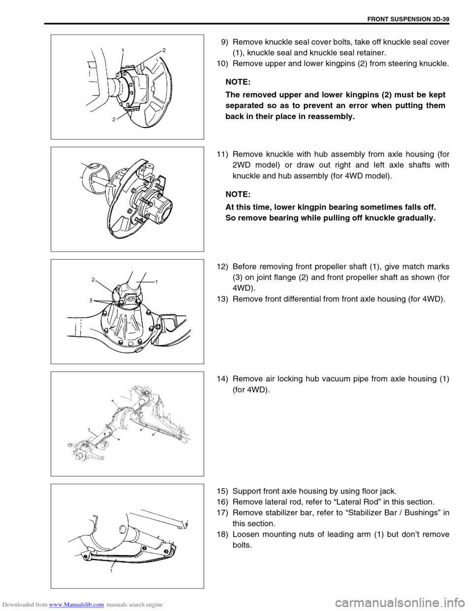
9) Remove knuckle seal cover bolts, take off knuckle seal cover
(1), knuckle seal and knuckle seal retainer.
10) Remove upper and lower kingpins (2) from steering knuckle.
11) Remove knuckle with hub assembly from axle housing (for
2WD model) or draw out right and left axle shafts with
knuckle and hub assembly (for 4WD model).
12) Before removing front propeller shaft (1), give match marks
(3) on joint flange (2) and front propeller shaft as shown (for
4WD).
13) Remove front differential from front axle housing (for 4WD).
14) Remove air locking hub vacuum pipe from axle housing (1)
(for 4WD).
15) Support front axle housing by using floor jack.
16) Remove lateral rod, refer to “Lateral Rod” in this section.
17) Remove stabilizer bar, refer to “Stabilizer Bar / Bushings” in
this section.
18) Loosen mounting nuts of leading arm (1) but don’t remove
bolts. NOTE:
The removed upper and lower kingpins (2) must be kept
separated so as to prevent an error when putting them
back in their place in reassembly.
NOTE:
At this time, lower kingpin bearing sometimes falls off.
So remove bearing while pulling off knuckle gradually.
Page 214 of 687
Downloaded from www.Manualslib.com manuals search engine FRONT SUSPENSION 3D-41
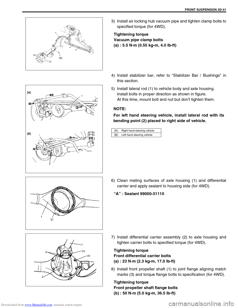
3) Install air locking hub vacuum pipe and tighten clamp bolts to
specified torque (for 4WD).
Tightening torque
Vacuum pipe clamp bolts
(a) : 5.5 N·m (0.55 kg-m, 4.0 lb-ft)
4) Install stabilizer bar, refer to “Stabilizer Bar / Bushings” in
this section.
5) Install lateral rod (1) to vehicle body and axle housing.
Install bolts in proper direction as shown in figure.
At this time, mount bolt and nut but don't tighten them.
6) Clean mating surfaces of axle housing (1) and differential
carrier and apply sealant to housing side (for 4WD).
“A” : Sealant 99000-31110
7) Install differential carrier assembly (2) to axle housing and
tighten carrier bolts to specified torque (for 4WD).
Tightening torque
Front differential carrier bolts
(a) : 23 N·m (2.3 kg-m, 17.0 lb-ft)
8) Install front propeller shaft (1) to joint flange aligning match
marks (3) and torque flange bolts to specification (for 4WD).
Tightening torque
Front propeller shaft flange bolts
(b) : 50 N·m (5.0 kg-m, 36.5 lb-ft)
NOTE:
For left hand steering vehicle, install lateral rod with its
bending point (2) placed to right side of vehicle.
[A] : Right hand steering vehicle
[B] : Left hand steering vehicle
Page 217 of 687

Downloaded from www.Manualslib.com manuals search engine 3D-44 FRONT SUSPENSION
Tightening Torque Specifications
Required Service Material
Fastening partTightening torque
Nm kg-m lb-ft
Stabilizer mount bracket bolt 20 2.0 14.5
Stabilizer ball joint nut 50 5.0 36.5
Shock absorber lock nut 29 2.9 21.0
Shock absorber lower nut 90 9.0 65.0
Brake caliper carrier bolt 85 8.5 61.5
Wheel bearing lock nut 220 22.0 160.0
Wheel bearing lock washer screw 1.5 0.15 1.0
Air locking hub bolt 48 4.8 35.0
Wheel spindle bolt 50 5.0 36.5
Kingpin bolt 25 2.5 18.0
Knuckle seal cover bolt 10 1.0 7.5
Tie-rod end nut
43 4.3 31.5
Drag-rod end nut (Knuckle side)
Lateral rod bolt and nut
90 9.0 65.0
Leading arm nut
Front differential carrier bolt 23 2.3 17.0
Front propeller shaft flange bolt 50 5.0 36.5
Wheel nut 95 9.5 69.0
Vacuum pipe clamp bolt 5.5 0.55 4.0
MaterialRecommended SUZUKI product
(Part Number)Use
Lithium grease SUZUKI SUPER GREASE (A)
(99000-25010)Knuckle seal / axle shaft oil seal
Recess of wheel spindles
Wheel hub oil seal
Wheel bearing
Spindle thrust washer
Spindle bush (inside and flange
part)
Spindle oil seal
SUZUKI SUPER GREASE (C)
(99000-25030)Kingpin bearing
Axle shaft joint (for 4WD)
Sealant SUZUKI BOND NO. 1215
(99000-31110)Mating surfaces of wheel spindle
and knuckle
Mating surface of differential carrier
and axle housing
Sealing compound SUZUKI SEALING COMPOUND
366E
(99000-31090)Mating surface of wheel spindle and
knuckle
Kingpin
Mating surfaces of hub cap and
wheel hub
Page 249 of 687
Downloaded from www.Manualslib.com manuals search engine 3F-6 WHEELS AND TIRES
Maintenance and Minor Adjustments
Wheel and Tire
Wheel repairs that use welding, heating, or peening are not approved. All damaged wheels should be replaced.
Studs
If a broken stud is found, see Section 3E (rear) or Section 3D (front) for Note and Replacement procedure.
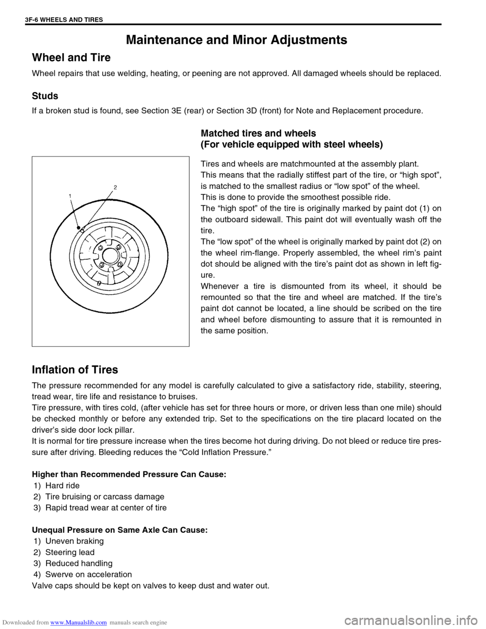
Matched tires and wheels
(For vehicle equipped with steel wheels)
Tires and wheels are matchmounted at the assembly plant.
This means that the radially stiffest part of the tire, or “high spot”,
is matched to the smallest radius or “low spot” of the wheel.
This is done to provide the smoothest possible ride.
The “high spot” of the tire is originally marked by paint dot (1) on
the outboard sidewall. This paint dot will eventually wash off the
tire.
The “low spot” of the wheel is originally marked by paint dot (2) on
the wheel rim-flange. Properly assembled, the wheel rim’s paint
dot should be aligned with the tire’s paint dot as shown in left fig-
ure.
Whenever a tire is dismounted from its wheel, it should be
remounted so that the tire and wheel are matched. If the tire’s
paint dot cannot be located, a line should be scribed on the tire
and wheel before dismounting to assure that it is remounted in
the same position.
Inflation of Tires
The pressure recommended for any model is carefully calculated to give a satisfactory ride, stability, steering,
tread wear, tire life and resistance to bruises.
Tire pressure, with tires cold, (after vehicle has set for three hours or more, or driven less than one mile) should
be checked monthly or before any extended trip. Set to the specifications on the tire placard located on the
driver’s side door lock pillar.
It is normal for tire pressure increase when the tires become hot during driving. Do not bleed or reduce tire pres-
sure after driving. Bleeding reduces the “Cold Inflation Pressure.”
Higher than Recommended Pressure Can Cause:
1) Hard ride
2) Tire bruising or carcass damage
3) Rapid tread wear at center of tire
Unequal Pressure on Same Axle Can Cause:
1) Uneven braking
2) Steering lead
3) Reduced handling
4) Swerve on acceleration
Valve caps should be kept on valves to keep dust and water out.
Page 250 of 687
Downloaded from www.Manualslib.com manuals search engine WHEELS AND TIRES 3F-7
Lower than Recommended Pressure Can Cause:
1) Tire squeal on turns
2) Hard steering
3) Rapid and uneven wear on the edges of the tread
4) Tire rim bruises and rupture
5) Tire cord breakage
6) High tire temperatures
7) Reduced handling
8) High fuel consumption
Tire placard
The tire placard is located on the driver’s side door lock pillar and should be referred to for tire information. The
placard lists the maximum load, tire size and cold tire pressure where applicable.
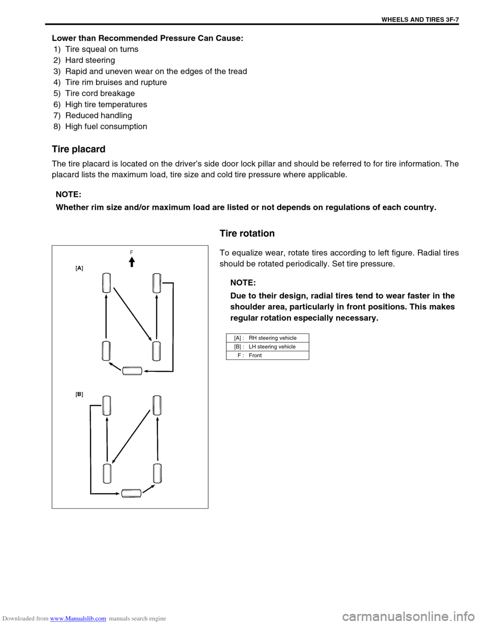
Tire rotation
To equalize wear, rotate tires according to left figure. Radial tires
should be rotated periodically. Set tire pressure. NOTE:
Whether rim size and/or maximum load are listed or not depends on regulations of each country.
NOTE:
Due to their design, radial tires tend to wear faster in the
shoulder area, particularly in front positions. This makes
regular rotation especially necessary.
[A] : RH steering vehicle
[B] : LH steering vehicle
F : Front
Page 262 of 687
Downloaded from www.Manualslib.com manuals search engine BRAKES 5-1
6F1
6F2
6G
6H
6K
7A
7A1
7B1
7C1
7D
7E
5
9
10
10A
10B
9
10
10A
10B
SECTION 5
BRAKES
CONTENTS
General Description ......................................... 5-3
Diagnosis .......................................................... 5-4
Road Testing Brakes ...................................... 5-4
Brake Fluid Leaks .......................................... 5-4
Substandard or Contaminated Brake Fluid .... 5-4
Diagnosis Table ............................................. 5-5
Brake Pedal Free Height Adjustment ............. 5-8
Brake Pedal Play Check ................................ 5-8
Stop Light Switch Adjustment ........................ 5-8
Excessive Pedal Travel Check ....................... 5-9
Front Brake Disc Check ................................. 5-9
Front Brake Pad Check .................................. 5-9
Rear Brake Shoe Check .............................. 5-10
Master Cylinder and Brake Fluid Level
Check ........................................................... 5-10
Rear Drum Brake Shoe Adjustment ............. 5-11
Parking Brake Inspection and Adjustment ... 5-11
Booster Operation Check ............................. 5-12Fluid Pressure Test
(If Equipped with LSPV) ............................... 5-15
On-Vehicle Service ........................................ 5-17
Air Bleeding of Brake System ...................... 5-17
Brake Hose and Pipe Inspection.................. 5-18
Front Disc Brake .......................................... 5-19
Brake pad ................................................. 5-20
Caliper assembly...................................... 5-22
Brake Disc.................................................... 5-26
Rear Brake ................................................... 5-29
Brake drum............................................... 5-29
Brake shoe ............................................... 5-32
Wheel Cylinder............................................. 5-33
Brake back plate ...................................... 5-34
Master Cylinder .............................................. 5-36
Master Cylinder Reservoir ........................... 5-36
Master Cylinder Assembly ........................... 5-37 WARNING:
For lifting point of vehicle, refer to Section 0A.
WARNING:
For vehicles equipped with Supplement Restraint (Air Bag) System:
Service on and around the air bag system components or wiring must be performed only by an
authorized SUZUKI dealer. Refer to “Air Bag System Components and Wiring Location View” under
“General Description” in air bag system section in order to confirm whether you are performing ser-
vice on or near the air bag system components or wiring. Please observe all WARNINGS and “Ser-
vice Precautions” under “On-Vehicle Service” in air bag system section before performing service
on or around the air bag system components or wiring. Failure to follow WARNINGS could result in
unintentional activation of the system or could render the system inoperative. Either of these two
conditions may result in severe injury.
Technical service work must be started at least 90 seconds after the ignition switch is turned to the
“LOCK” position and the negative cable is disconnected from the battery. Otherwise, the system
may be activated by reserve energy in the Sensing and Diagnostic Module (SDM).
NOTE:
When inspecting and servicing vehicle equipped with ABS, be sure to refer to section 5E first.
All brake fasteners are important attaching parts in that they could affect the performance of vital
parts and systems, and/or could result in major repair expense. They must be replaced with one of
same part number or with an equivalent part if replacement becomes necessary. Do not use a
replacement part of lesser quality or substitute design. Torque values must be used as specified
during reassembly to assure proper retention of all parts. There is to be no welding as it may result
in extensive damage and weakening of the metal.