harness SUZUKI SWIFT 2000 1.G RG413 Service User Guide
[x] Cancel search | Manufacturer: SUZUKI, Model Year: 2000, Model line: SWIFT, Model: SUZUKI SWIFT 2000 1.GPages: 698, PDF Size: 16.01 MB
Page 57 of 698
1A-6 HEATER AND VENTILATION
REMOVAL
1) Disconnect negative (–) cable at battery.
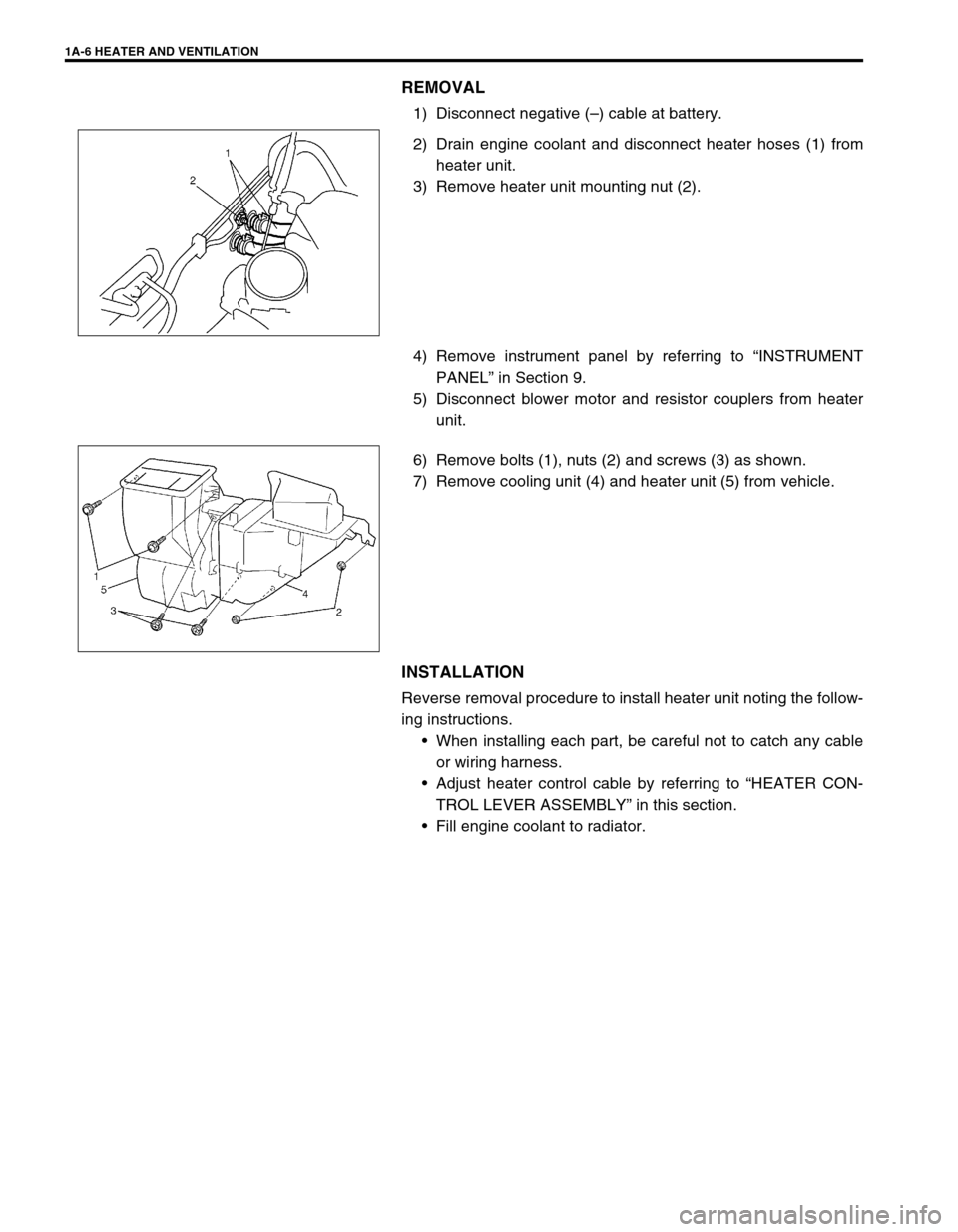
2) Drain engine coolant and disconnect heater hoses (1) from
heater unit.
3) Remove heater unit mounting nut (2).
4) Remove instrument panel by referring to “INSTRUMENT
PANEL” in Section 9.
5) Disconnect blower motor and resistor couplers from heater
unit.
6) Remove bolts (1), nuts (2) and screws (3) as shown.
7) Remove cooling unit (4) and heater unit (5) from vehicle.
INSTALLATION
Reverse removal procedure to install heater unit noting the follow-
ing instructions.
When installing each part, be careful not to catch any cable
or wiring harness.
Adjust heater control cable by referring to “HEATER CON-
TROL LEVER ASSEMBLY” in this section.
Fill engine coolant to radiator.
Page 83 of 698
1B-18 AIR CONDITIONING (OPTIONAL)
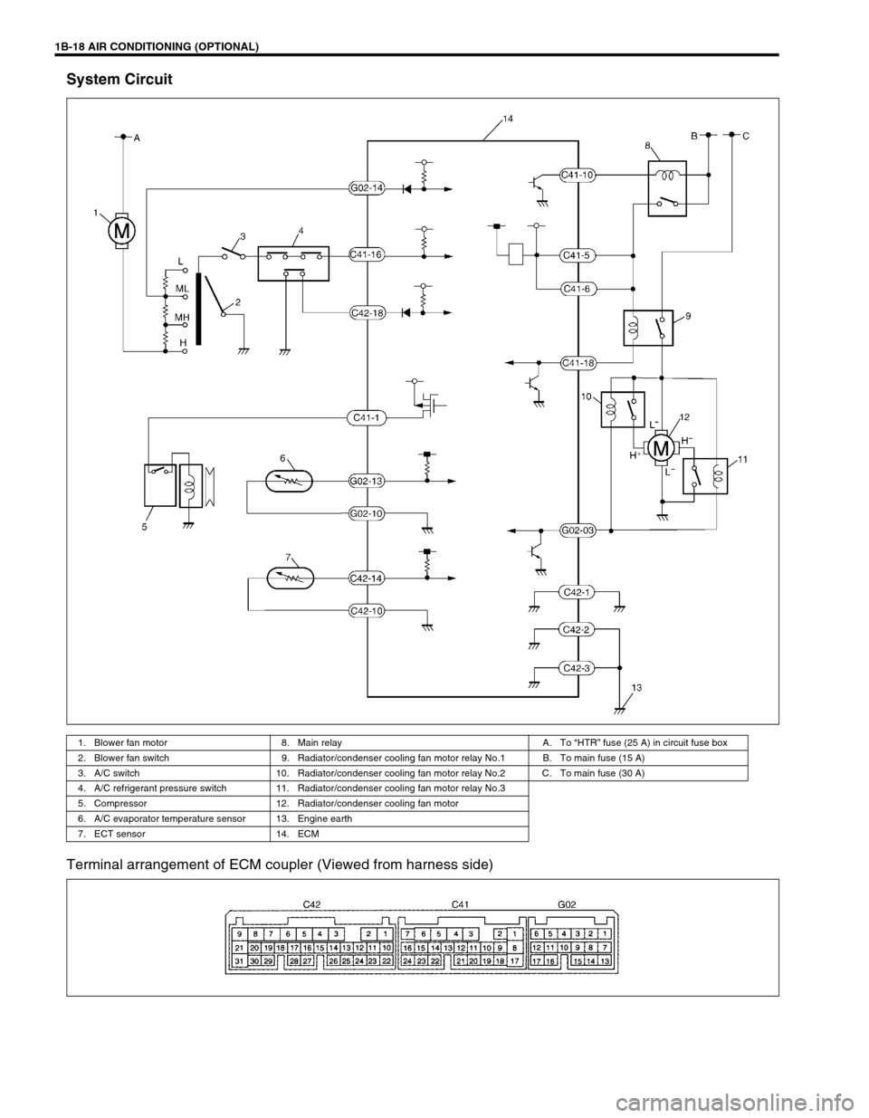
System Circuit
Terminal arrangement of ECM coupler (Viewed from harness side)
1. Blower fan motor 8. Main relay A. To “HTR” fuse (25 A) in circuit fuse box
2. Blower fan switch 9. Radiator/condenser cooling fan motor relay No.1 B. To main fuse (15 A)
3. A/C switch 10. Radiator/condenser cooling fan motor relay No.2 C. To main fuse (30 A)
4. A/C refrigerant pressure switch 11. Radiator/condenser cooling fan motor relay No.3
5. Compressor 12. Radiator/condenser cooling fan motor
6. A/C evaporator temperature sensor 13. Engine earth
7. ECT sensor 14. ECM
Page 178 of 698
STEERING WHEEL AND COLUMN 3C-5
INSPECTION
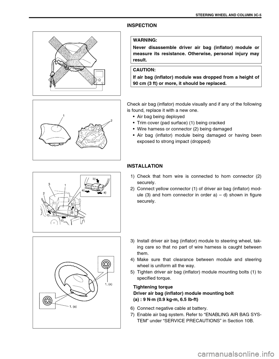
Check air bag (inflator) module visually and if any of the following
is found, replace it with a new one.
Air bag being deployed
Trim cover (pad surface) (1) being cracked
Wire harness or connector (2) being damaged
Air bag (inflator) module being damaged or having been
exposed to strong impact (dropped)
INSTALLATION
1) Check that horn wire is connected to horn connector (2)
securely.
2) Connect yellow connector (1) of driver air bag (inflator) mod-
ule (3) and horn connector in order a) – d) shown in figure
securely.
3) Install driver air bag (inflator) module to steering wheel, tak-
ing care so that no part of wire harness is caught between
them.
4) Make sure that clearance between module and steering
wheel is uniform all the way.
5) Tighten driver air bag (inflator) module mounting bolts (1) to
specified torque.
Tightening torque
Driver air bag (inflator) module mounting bolt
(a) : 9 N·m (0.9 kg-m, 6.5 lb-ft)
6) Connect negative cable at battery.
7) Enable air bag system. Refer to “ENABLING AIR BAG SYS-
TEM” under “SERVICE PRECAUTIONS” in Section 10B. WARNING:
Never disassemble driver air bag (inflator) module or
measure its resistance. Otherwise, personal injury may
result.
CAUTION:
If air bag (inflator) module was dropped from a height of
90 cm (3 ft) or more, it should be replaced.
Page 182 of 698
STEERING WHEEL AND COLUMN 3C-9
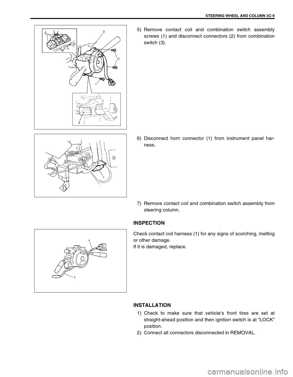
5) Remove contact coil and combination switch assembly
screws (1) and disconnect connectors (2) from combination
switch (3).
6) Disconnect horn connector (1) from instrument panel har-
ness.
7) Remove contact coil and combination switch assembly from
steering column.
INSPECTION
Check contact coil harness (1) for any signs of scorching, melting
or other damage.
If it is damaged, replace.
INSTALLATION
1) Check to make sure that vehicle’s front tires are set at
straight-ahead position and then ignition switch is at “LOCK”
position.
2) Connect all connectors disconnected in REMOVAL.
Page 336 of 698
ANTILOCK BRAKE SYSTEM (ABS) 5E-11
c) Diagnostic Trouble Code (DTC) Check, Record and Clearance
Perform “DIAGNOSTIC TROUBLE CODE CHECK” procedure in this section, record it and then clear it
referring to “DIAGNOSTIC TROUBLE CODE CLEARANCE” in this section.
If the malfunction DTC which was once displayed and then cleared cannot be detected (indicated) again
when the ignition switch is turned ON, attempt to diagnose the trouble based on the DTC recorded in this
step may mislead the diagnosis or make diagnosing difficult. Proceed to Step 2) to check control module
for proper self-diagnosis function.
If the malfunction DTC which was once displayed and then cleared can be detected (indicated) again when
ignition switch is turned ON, proceed to Step 3).
2) DRIVING TEST
Test drive the vehicle at 40 km/h for more than a minute and check if any trouble symptom (such as abnor-
mal lighting of ABS warning light) exists.
If the malfunction DTC is confirmed again at ignition switch ON, driving test as described in above is not nec-
essary. Proceed to Step 3).
3) DIAGNOSTIC TROUBLE CODE CHECK
Recheck diagnostic trouble code referring to “DTC CHECK” as shown in the following page.
4) DIAGNOSTIC TROUBLE CODE FLOW TABLE
According to Diagnostic flow table for the diagnostic trouble code confirmation in Step 3), locate the cause of
the trouble, namely in a sensor, switch, wire harness, connector, actuator assembly or other part and repair
or replace faulty parts.
5)“DIAGNOSIS” IN “BRAKES” SECTION
Check the parts or system suspected as a possible cause referring to “DIAGNOSIS” in “BRAKES” section
and based on symptoms appearing on the vehicle (symptom obtained through Steps 1)-a, 1)-b and 2) and
repair or replace faulty parts, if any).
6) CHECK FOR INTERMITTENT PROBLEM
Check parts where an intermittent trouble is easy to occur (e.g., wire harness, connector, etc.), referring to
“INTERMITTENT TROUBLE” in “GENERAL INFORMATION” section and related circuit of trouble code
recorded in Step 1)-c.
7) FINAL CONFIRMATION TEST
Confirm that the problem symptom has gone and the ABS is free from any abnormal conditions. If what has
been repaired is related to the malfunction DTC, clear the DTC once and perform test driving and confirm
that no DTC is indicated.
Page 347 of 698
5E-22 ANTILOCK BRAKE SYSTEM (ABS)
DTC C1013 (DTC 13) – SYSTEM SPECIFICATIONS DIFFERENT FROM ABS
CONTROL MODULE SPECIFICATIONS
DESCRIPTION
When abnormal signal is inputted to a no-used terminal of control module white running or wrong ABS hydraulic
unit/control module assembly is installed, this DTC will be set.
INSPECTION
1) Ignition switch OFF.
2) Check for proper connection from harness to control module.
3) If OK, substitute a known-good and correct specifications ABS hydraulic unit/control module assembly.
4) Recheck system.
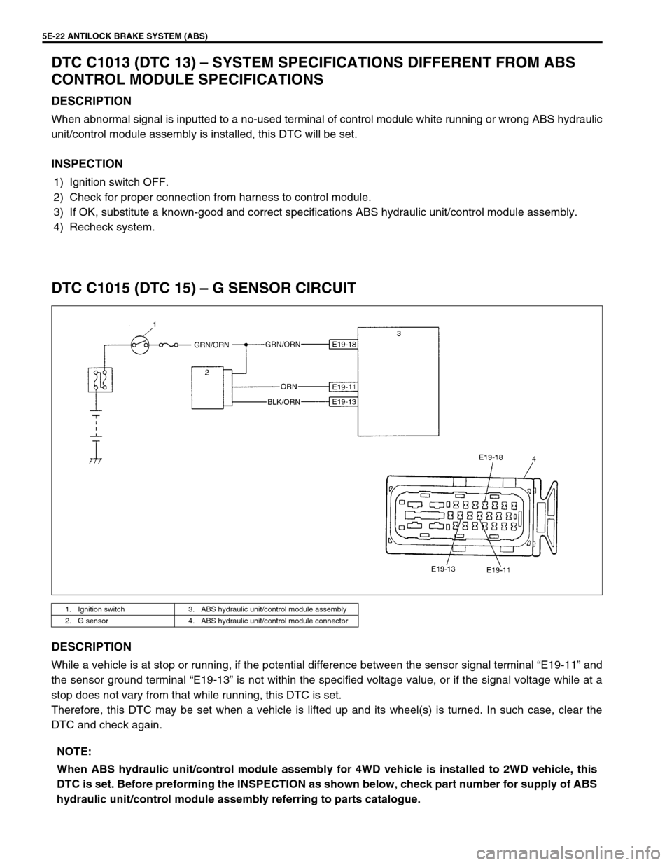
DTC C1015 (DTC 15) – G SENSOR CIRCUIT
DESCRIPTION
While a vehicle is at stop or running, if the potential difference between the sensor signal terminal “E19-11” and
the sensor ground terminal “E19-13” is not within the specified voltage value, or if the signal voltage while at a
stop does not vary from that while running, this DTC is set.
Therefore, this DTC may be set when a vehicle is lifted up and its wheel(s) is turned. In such case, clear the
DTC and check again.
1. Ignition switch 3. ABS hydraulic unit/control module assembly
2. G sensor 4. ABS hydraulic unit/control module connector
NOTE:
When ABS hydraulic unit/control module assembly for 4WD vehicle is installed to 2WD vehicle, this
DTC is set. Before preforming the INSPECTION as shown below, check part number for supply of ABS
hydraulic unit/control module assembly referring to parts catalogue.
Page 361 of 698
5E-36 ANTILOCK BRAKE SYSTEM (ABS)
Reference
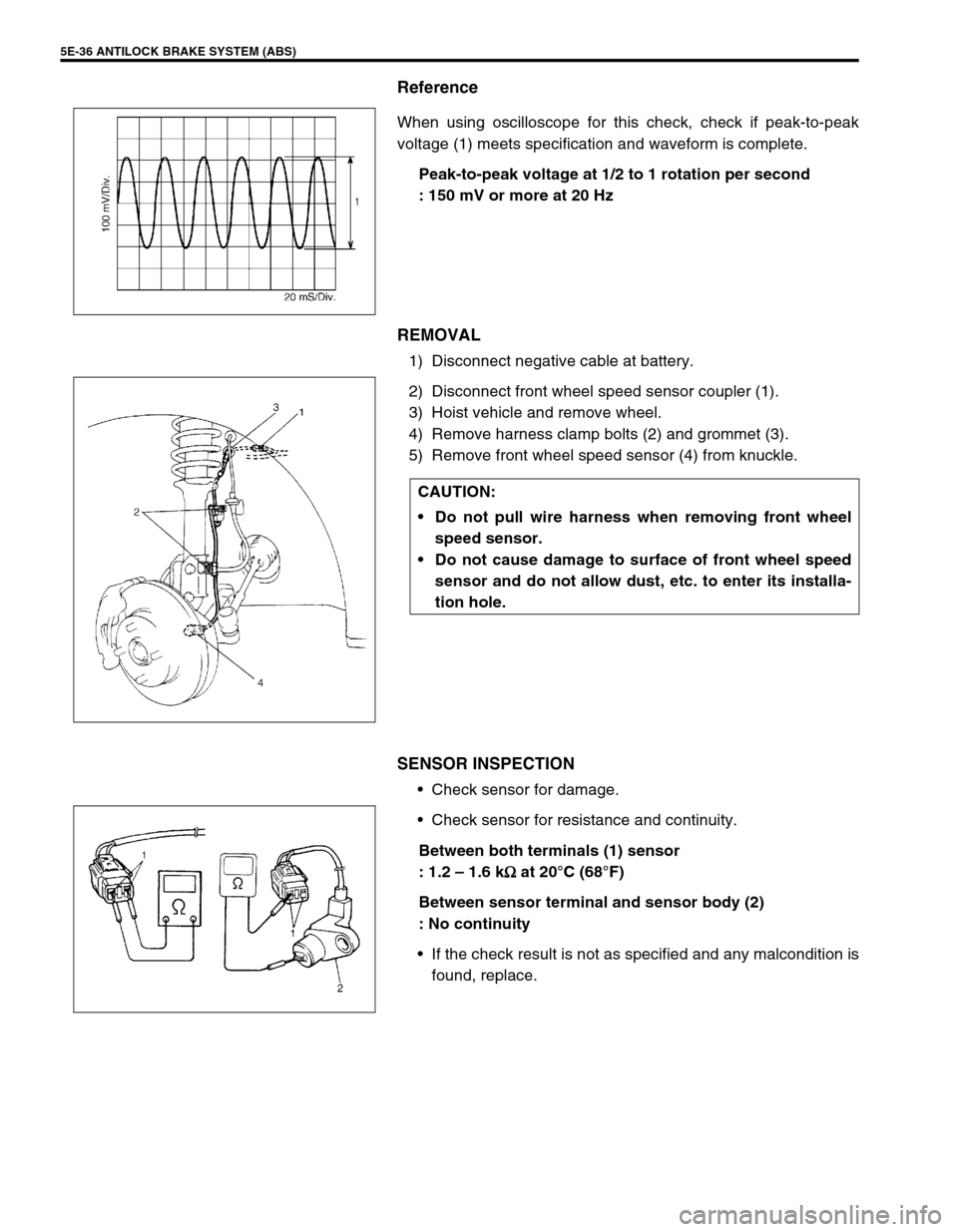
When using oscilloscope for this check, check if peak-to-peak
voltage (1) meets specification and waveform is complete.
Peak-to-peak voltage at 1/2 to 1 rotation per second
: 150 mV or more at 20 Hz
REMOVAL
1) Disconnect negative cable at battery.
2) Disconnect front wheel speed sensor coupler (1).
3) Hoist vehicle and remove wheel.
4) Remove harness clamp bolts (2) and grommet (3).
5) Remove front wheel speed sensor (4) from knuckle.
SENSOR INSPECTION
Check sensor for damage.
Check sensor for resistance and continuity.
Between both terminals (1) sensor
: 1.2 – 1.6 k
Ω
ΩΩ Ω at 20°C (68°F)
Between sensor terminal and sensor body (2)
: No continuity
If the check result is not as specified and any malcondition is
found, replace.
CAUTION:
Do not pull wire harness when removing front wheel
speed sensor.
Do not cause damage to surface of front wheel speed
sensor and do not allow dust, etc. to enter its installa-
tion hole.
Page 362 of 698
ANTILOCK BRAKE SYSTEM (ABS) 5E-37
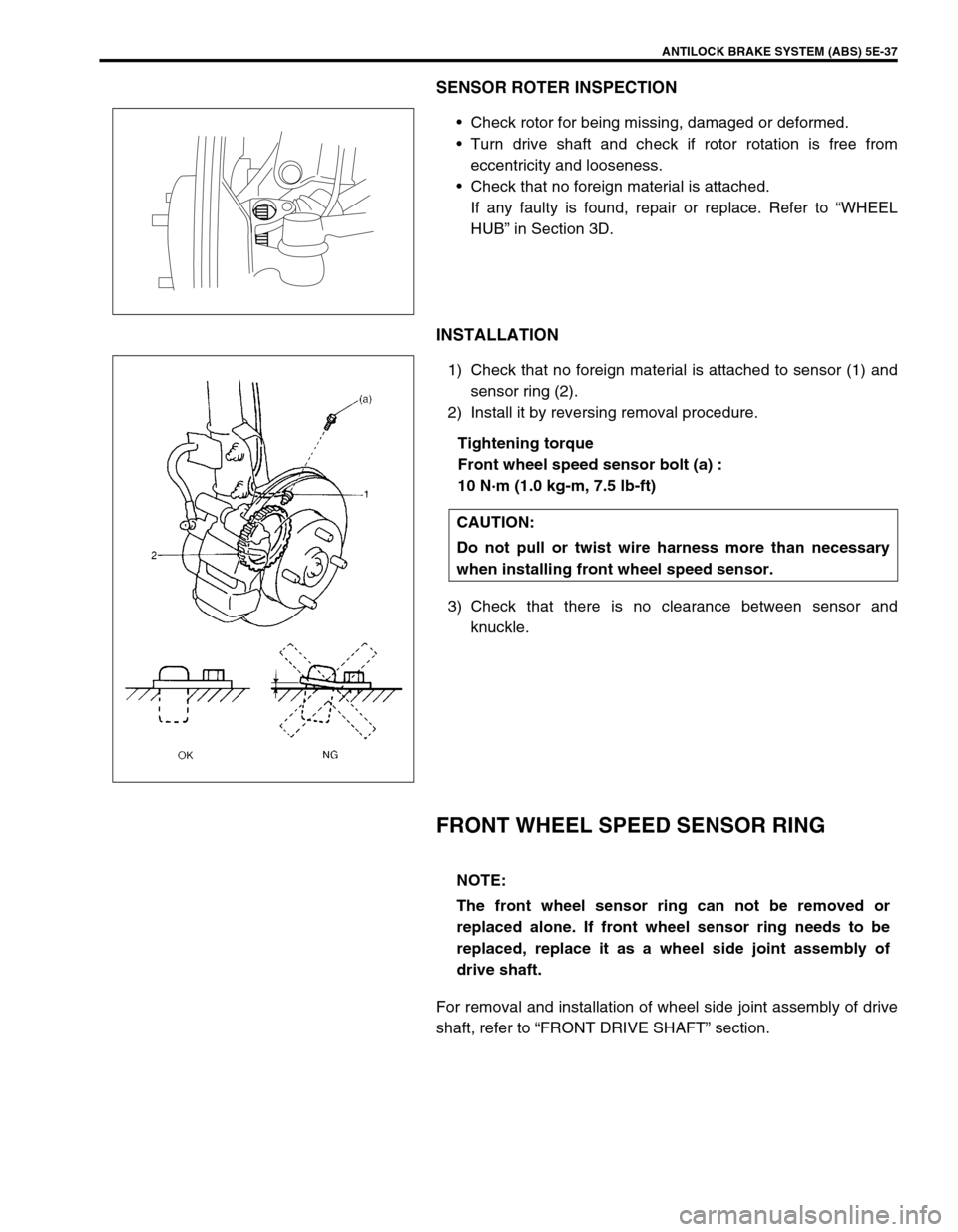
SENSOR ROTER INSPECTION
Check rotor for being missing, damaged or deformed.
Turn drive shaft and check if rotor rotation is free from
eccentricity and looseness.
Check that no foreign material is attached.
If any faulty is found, repair or replace. Refer to “WHEEL
HUB” in Section 3D.
INSTALLATION
1) Check that no foreign material is attached to sensor (1) and
sensor ring (2).
2) Install it by reversing removal procedure.
Tightening torque
Front wheel speed sensor bolt (a) :
10 N·m (1.0 kg-m, 7.5 lb-ft)
3) Check that there is no clearance between sensor and
knuckle.
FRONT WHEEL SPEED SENSOR RING
For removal and installation of wheel side joint assembly of drive
shaft, refer to “FRONT DRIVE SHAFT” section.
CAUTION:
Do not pull or twist wire harness more than necessary
when installing front wheel speed sensor.
NOTE:
The front wheel sensor ring can not be removed or
replaced alone. If front wheel sensor ring needs to be
replaced, replace it as a wheel side joint assembly of
drive shaft.
Page 364 of 698
ANTILOCK BRAKE SYSTEM (ABS) 5E-39
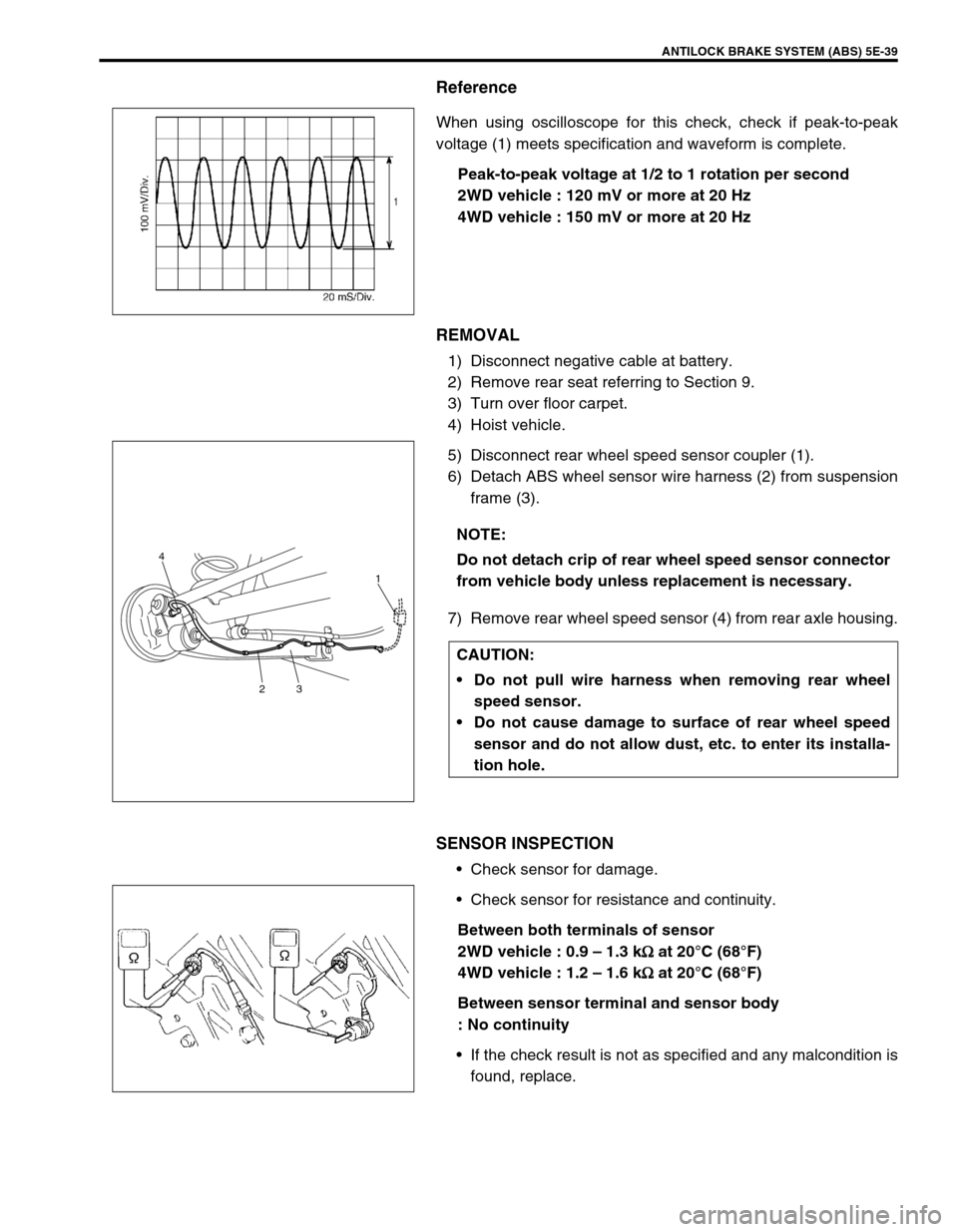
Reference
When using oscilloscope for this check, check if peak-to-peak
voltage (1) meets specification and waveform is complete.
Peak-to-peak voltage at 1/2 to 1 rotation per second
2WD vehicle : 120 mV or more at 20 Hz
4WD vehicle : 150 mV or more at 20 Hz
REMOVAL
1) Disconnect negative cable at battery.
2) Remove rear seat referring to Section 9.
3) Turn over floor carpet.
4) Hoist vehicle.
5) Disconnect rear wheel speed sensor coupler (1).
6) Detach ABS wheel sensor wire harness (2) from suspension
frame (3).
7) Remove rear wheel speed sensor (4) from rear axle housing.
SENSOR INSPECTION
Check sensor for damage.
Check sensor for resistance and continuity.
Between both terminals of sensor
2WD vehicle : 0.9 – 1.3 k
Ω
ΩΩ Ω at 20°C (68°F)
4WD vehicle : 1.2 – 1.6 k
Ω
ΩΩ Ω at 20°C (68°F)
Between sensor terminal and sensor body
: No continuity
If the check result is not as specified and any malcondition is
found, replace.
NOTE:
Do not detach crip of rear wheel speed sensor connector
from vehicle body unless replacement is necessary.
CAUTION:
Do not pull wire harness when removing rear wheel
speed sensor.
Do not cause damage to surface of rear wheel speed
sensor and do not allow dust, etc. to enter its installa-
tion hole.
4
231
Page 365 of 698
5E-40 ANTILOCK BRAKE SYSTEM (ABS)
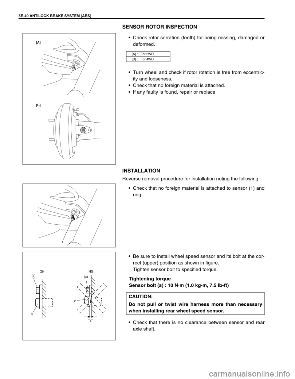
SENSOR ROTOR INSPECTION
Check rotor serration (teeth) for being missing, damaged or
deformed.
Turn wheel and check if rotor rotation is free from eccentric-
ity and looseness.
Check that no foreign material is attached.
If any faulty is found, repair or replace.
INSTALLATION
Reverse removal procedure for installation noting the following.
Check that no foreign material is attached to sensor (1) and
ring.
Be sure to install wheel speed sensor and its bolt at the cor-
rect (upper) position as shown in figure.
Tighten sensor bolt to specified torque.
Tightening torque
Sensor bolt (a) : 10 N·m (1.0 kg-m, 7.5 lb-ft)
Check that there is no clearance between sensor and rear
axle shaft.
[A] : For 2WD
[B] : For 4WD
[B] [A]
1
CAUTION:
Do not pull or twist wire harness more than necessary
when installing rear wheel speed sensor.