axle removal SUZUKI SWIFT 2006 2.G Service Workshop Manual
[x] Cancel search | Manufacturer: SUZUKI, Model Year: 2006, Model line: SWIFT, Model: SUZUKI SWIFT 2006 2.GPages: 1496, PDF Size: 34.44 MB
Page 42 of 1496
Downloaded from www.Manualslib.com manuals search engine 0B-12 Maintenance and Lubrication:
HVAC Air Filter (If Equipped) InspectionS7RS0B0206032
1) Remove HVAC air filter from HVAC unit referring to
“HVAC Air Filter Removal and Installation (If
Equipped) in Section 7A”.
2) Check for dirt and dust. If HVAC air filter is excessively dirty, replace HVAC air filter with new
one. If not, go to next step.
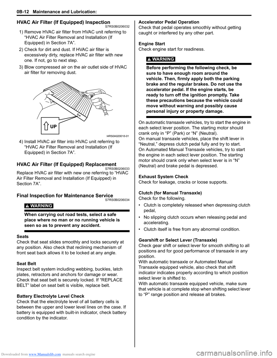
3) Blow compressed air on the air outlet side of HVAC air filter for removing dust.
4) Install HVAC air filter in to HVAC unit referring to
“HVAC Air Filter Removal and Installation (If
Equipped) in Section 7A”.
HVAC Air Filter (If Equipped) ReplacementS7RS0B0206033
Replace HVAC air filter with new one referring to “HVAC
Air Filter Removal and Installation (If Equipped) in
Section 7A”.
Final Inspection for Maintenance ServiceS7RS0B0206034
WARNING!
When carrying out road tests, select a safe
place where no man or no running vehicle is
seen so as to prevent any accident.
Seats
Check that seat slides smoot hly and locks securely at
any position. Also check that reclining mechanism of
front seat back allows it to be locked at any angle.
Seat Belt
Inspect belt system including webbing, buckles, latch
plates, retractors and anchors for damage or wear.
Check that seat belt is securely locked. If “REPLACE
BELT” label on seat belt is visible, replace belt.
Battery Electrolyte Level Check
Check that the electrolyte le vel of all battery cells is
between the upper and lower level lines on the case. If
battery is equipped with built-in indicator, check battery
condition by the indicator. Accelerator Pedal Operation
Check that pedal operates
smoothly without getting
caught or interfered by any other part.
Engine Start
Check engine start for readiness.
WARNING!
Before performing th e following check, be
sure to have enough room around the
vehicle. Then, firmly apply both the parking
brake and the regular brakes. Do not use the
accelerator pedal. If the engine starts, be
ready to turn off the ignition promptly. Take
these precautions because the vehicle could
move without warning and possibly cause
personal injury or property damage.
On automatic transaxle vehicles, try to start the engine in
each select lever position. The starting motor should
crank only in “P” (Park) or “N” (Neutral).
On manual transaxle vehicles, place the shift lever in
“Neutral,” depress clutch pedal fully and try to start.
On Automated Manual Transaxl e vehicles, try to start
the engine in each select le ver position. The starting
motor should crank only when select lever is in “N”
(Neutral) and brake pedal is depressed.
Exhaust System Check
Check for leakage, cracks or loose supports.
Clutch (for Manual Transaxle)
Check for the following.
• Clutch is completely released when depressing clutch pedal,
• No slipping clutch occurs when releasing pedal and accelerating.
• Clutch itself is free fr om any abnormal condition.
Gearshift or Select Lever (Transaxle)
Check gear shift or select lever for smooth shifting to all
positions and for good performance of transaxle in any
position.
With automatic transaxle or Automated Manual
Transaxle equipped vehicle, also check that shift
indicator indicates properly according to which position
select lever is shifted to.
With automatic transaxle equipped vehicle, make sure
that vehicle is at complete stop when shifting select lever
to “P” range position and release all brakes.
I4RS0A020018-01
Page 302 of 1496

Downloaded from www.Manualslib.com manuals search engine 1D-17 Engine Mechanical:
Engine Assembly Removal and InstallationS7RS0B1406011
NOTE
After replacing electric throttle body
assembly, perform calibration of throttle
valve referring to “Electric Throttle Body
System Calibration in Section 1C”.
Removal1) Relieve fuel pressure according to “Fuel Pressure Relief Procedure in Section 1G”.
2) Disconnect negative and pos itive cable at battery.
3) Remove battery and tray.
4) Remove engine hood after disconnecting windshield washer hose.
5) Remove right and left side engine under covers.
6) Remove A/C compressor belt by referring to “Compressor Drive Belt Remo val and Installation in
Section 7B” or “Compressor Drive Belt Removal and
Installation in Section 7B”.
7) Drain engine oil, transaxle oil and coolant.
8) Remove cowl top plate referring to “Cowl Top Components in Section 9K”.
9) Remove air cleaner assembly referring to “Air Cleaner Components”.
10) With hose connected, detach A/C compressor from its bracket (A/C model) referring to “Compressor
Assembly Removal and Installation in Section 7B” or
“Compressor Assembly Removal and Installation in
Section 7B”.
CAUTION!
Suspend removed A/C compressor at a place
where no damage will be caused during
removal and installation of engine assembly.
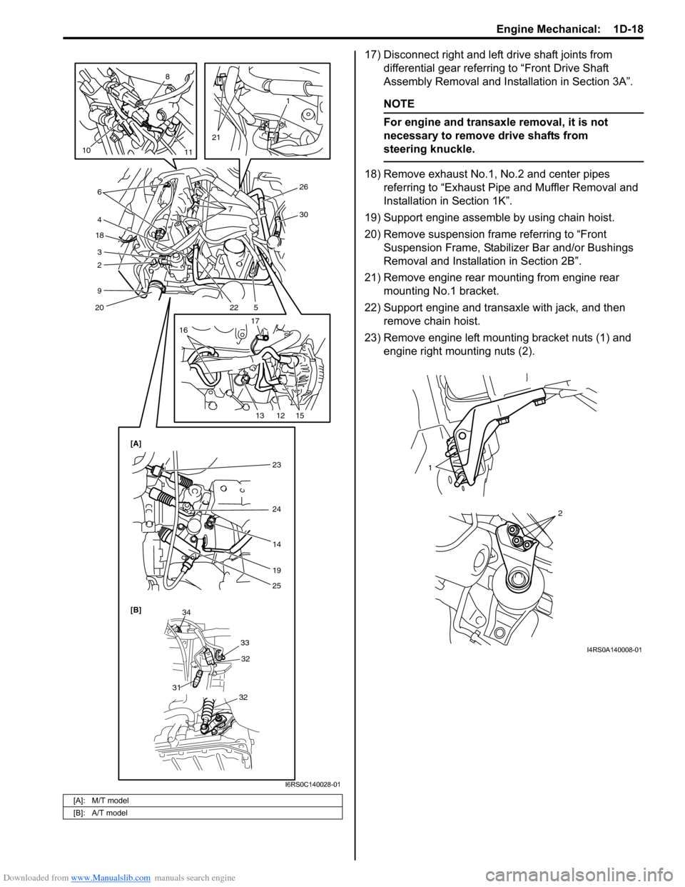
11) Remove intake manifold rear stiffener (1) from intake manifold and cylinder block. 12) Disconnect the following electric wires:
• MAP sensor (1)
• ECT sensor (2)
•EGR valve (3)
• CMP sensor (4)
• Electric throttle body assembly (5)
• Ignition coil assembly (6)
• Injectors (7)
• Heated oxygen sensor No. 2 (8) and No. 1 (9)
• Oil control valve (10)
• Engine oil pressure switch (11)
• CKP sensor (12)
• Knock sensor (13)
• Back up light switch (14)
• Generator (15)
• Starting motor (16)
• Ground terminal (17) from intake manifold
• Battery ground terminal (18) from exhaust manifold
• Battery ground cable (19) from transaxle
• Magnet clutch switch of A/C compressor (A/C model)
• Each wire harness clamps
• Output shaft speed sensor (VSS) (34) (A/T model)
• Solenoid valve (33) (A/T model)
• Transmission range sensor (32) (A/T model)
• Input shaft speed sensor (31) (A/T model)
13) Remove fuse box from its bracket.
14) Disconnect the following cables: • Gear select control cable (23) (M/T model)
• Gear shift control cable (24) (M/T model)
• A/T select cable (A/T model)
15) Disconnect the following hoses: • Brake booster hose (26) from intake manifold
• Radiator inlet and outlet hoses (20) from each pipe
• Heater inlet and outlet hoses (21) from each pipe
• Fuel feed hoses (22) from fuel feed pipe
• EVAP canister purge valve hose (30) from purge pipe
• A/T fluid cooler hoses (A/T model)
16) With hose connected, detach clutch operating cylinder (25). (M/T model)
CAUTION!
Suspend removed clutch operating cylinder
at a place where no damage will be caused
during removal and installation of engine
assembly.
1
I6RS0B141014-01
Page 303 of 1496
Downloaded from www.Manualslib.com manuals search engine Engine Mechanical: 1D-18
17) Disconnect right and left drive shaft joints from differential gear referring to “Front Drive Shaft
Assembly Removal and Installation in Section 3A”.
NOTE
For engine and transaxle removal, it is not
necessary to remove drive shafts from
steering knuckle.
18) Remove exhaust No.1, No.2 and center pipes referring to “Exhaust Pipe and Muffler Removal and
Installation in Section 1K”.
19) Support engine assemble by using chain hoist.
20) Remove suspension frame referring to “Front Suspension Frame, Stabiliz er Bar and/or Bushings
Removal and Installati on in Section 2B”.
21) Remove engine rear mounting from engine rear mounting No.1 bracket.
22) Support engine and transaxle with jack, and then remove chain hoist.
23) Remove engine left mounting bracket nuts (1) and engine right mounting nuts (2).
[A]: M/T model
[B]: A/T model
7
26
30
5
4
22
3
2
20
6
9
18
8
11
10
21 1
16
17
151213
[B]
23
24
14
25 19
34
33
32
32
31
[A]
I6RS0C140028-01
1
2
I4RS0A140008-01
Page 304 of 1496
Downloaded from www.Manualslib.com manuals search engine 1D-19 Engine Mechanical:
24) Before removing engine with transaxle from engine compartment, recheck to make sure all hoses,
electric wires and cables are disconnected from
engine and transaxle.
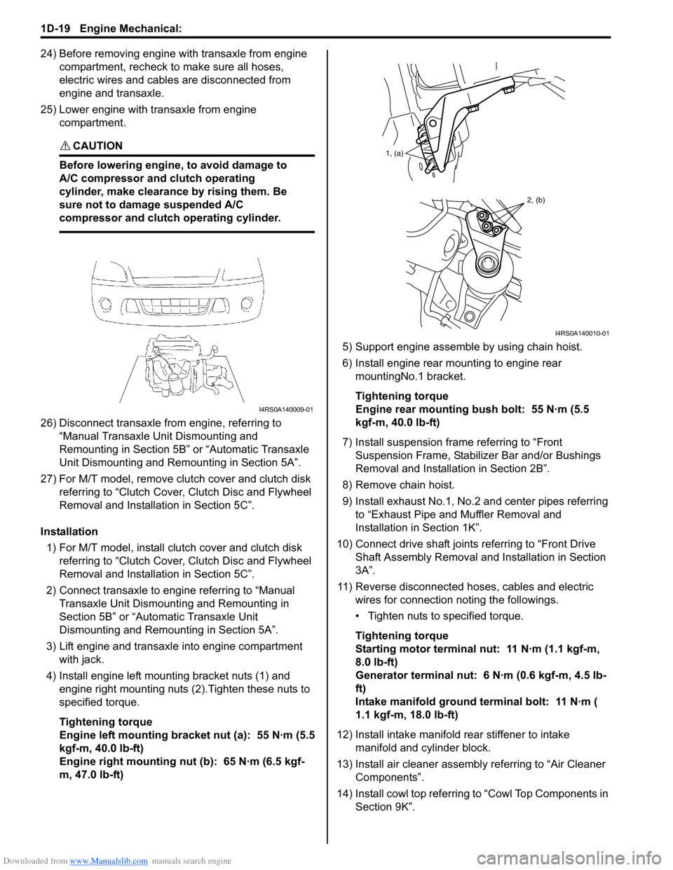
25) Lower engine with transaxle from engine compartment.
CAUTION!
Before lowering engine, to avoid damage to
A/C compressor and clutch operating
cylinder, make clearance by rising them. Be
sure not to damage suspended A/C
compressor and clutch operating cylinder.
26) Disconnect transaxle from engine, referring to “Manual Transaxle Unit Dismounting and
Remounting in Section 5B” or “Automatic Transaxle
Unit Dismounting and Re mounting in Section 5A”.
27) For M/T model, remove clutch cover and clutch disk referring to “Clutch Cover, Clutch Disc and Flywheel
Removal and Installa tion in Section 5C”.
Installation 1) For M/T model, install clutch cover and clutch disk referring to “Clutch Cover, Clutch Disc and Flywheel
Removal and Installa tion in Section 5C”.
2) Connect transaxle to engine referring to “Manual Transaxle Unit Dismounting and Remounting in
Section 5B” or “Automatic Transaxle Unit
Dismounting and Remounting in Section 5A”.
3) Lift engine and transaxle into engine compartment with jack.
4) Install engine left mounting bracket nuts (1) and engine right mounting nuts (2).Tighten these nuts to
specified torque.
Tightening torque
Engine left mounting bracket nut (a): 55 N·m (5.5
kgf-m, 40.0 lb-ft)
Engine right mounting nut (b): 65 N·m (6.5 kgf-
m, 47.0 lb-ft) 5) Support engine assemble by using chain hoist.
6) Install engine rear mounting to engine rear
mountingNo.1 bracket.
Tightening torque
Engine rear mounting bush bolt: 55 N·m (5.5
kgf-m, 40.0 lb-ft)
7) Install suspension frame referring to “Front Suspension Frame, Stabiliz er Bar and/or Bushings
Removal and Installati on in Section 2B”.
8) Remove chain hoist.
9) Install exhaust No.1, No.2 and center pipes referring to “Exhaust Pipe and Muffler Removal and
Installation in Section 1K”.
10) Connect drive shaft joints referring to “Front Drive Shaft Assembly Removal and Installation in Section
3A”.
11) Reverse disconnected hoses, cables and electric wires for connection noting the followings.
• Tighten nuts to specified torque.
Tightening torque
Starting motor terminal nut: 11 N·m (1.1 kgf-m,
8.0 lb-ft)
Generator terminal nut: 6 N·m (0.6 kgf-m, 4.5 lb-
ft)
Intake manifold ground terminal bolt: 11 N·m (
1.1 kgf-m, 18.0 lb-ft)
12) Install intake manifold rear stiffener to intake
manifold and cylinder block.
13) Install air cleaner assembly referring to “Air Cleaner Components”.
14) Install cowl top referring to “Cowl Top Components in
Section 9K”.
I4RS0A140009-01
1, (a)
2, (b)
I4RS0A140010-01
Page 305 of 1496
Downloaded from www.Manualslib.com manuals search engine Engine Mechanical: 1D-20
15) Install A/C compressor to its bracket (if equipped) referring to “Compressor Assembly Removal and
Installation in Section 7B” or “Compressor Assembly
Removal and Installa tion in Section 7B”.
16) Adjust A/C compressor belt tension (if equipped) referring to “Compressor Drive Belt Inspection and
Adjustment in Section 7B” or “Compressor Drive Belt
Inspection and Adjustment in Section 7B”.
17) Check to ensure that a ll removed parts are back in
place.
Reinstall any necessary parts which have not been
reinstalled.
18) Refill cooling system with coolant referring to “Cooling System Flush and Refill in Section 1F”. 19) Refill engine with engine oil
referring to “Engine Oil
and Filter Change in Section 0B”.
20) Refill transaxle with transa xle oil referring to“Manual
Transaxle Oil Change in Section 5B” or “A/T Fluid
Change in Section 5A”.
21) Install battery and tray.
22) Connect positive and negative cable at battery.
23) Install engine hood and connect windshield washer hose.
24) Verify that there is no fu el leakage, coolant leakage,
oil leakage and exhaust gas leakage at each
connection.
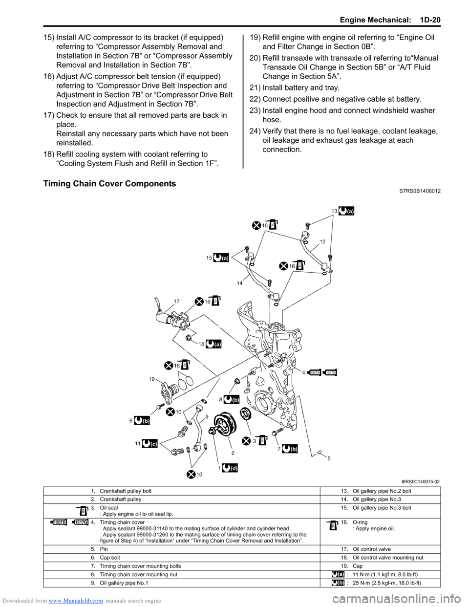
Timing Chain Cover ComponentsS7RS0B1406012
I6RS0C140015-02
1. Crankshaft pulley bolt 13. Oil gallery pipe No.2 bolt
2. Crankshaft pulley 14. Oil gallery pipe No.3
3. Oil seal : Apply engine oil to oil seal lip. 15. Oil gallery pipe No.3 bolt
4. Timing chain cover : Apply sealant 99000-31140 to the mating surface of cylinder and cylinder head.
: Apply sealant 99000-31260 to the mating surface of timing chain cover referring to the
figure of Step 4) of “Installation” under “Timing Chain Cover Removal and Installation”. 16. O-ring
: Apply engine oil.
5. Pin 17. Oil control valve
6. Cap bolt 18. Oil control valve mounting nut
7. Timing chain cover mounting bolts 19. Cap
8. Timing chain cover mounting nut : 11 N ⋅m (1.1 kgf-m, 8.0 lb-ft)
9. Oil gallery pipe No.1 :25 N⋅m (2.5 kgf-m, 18.0 lb-ft)
Page 357 of 1496
Downloaded from www.Manualslib.com manuals search engine Engine Lubrication System: 1E-5
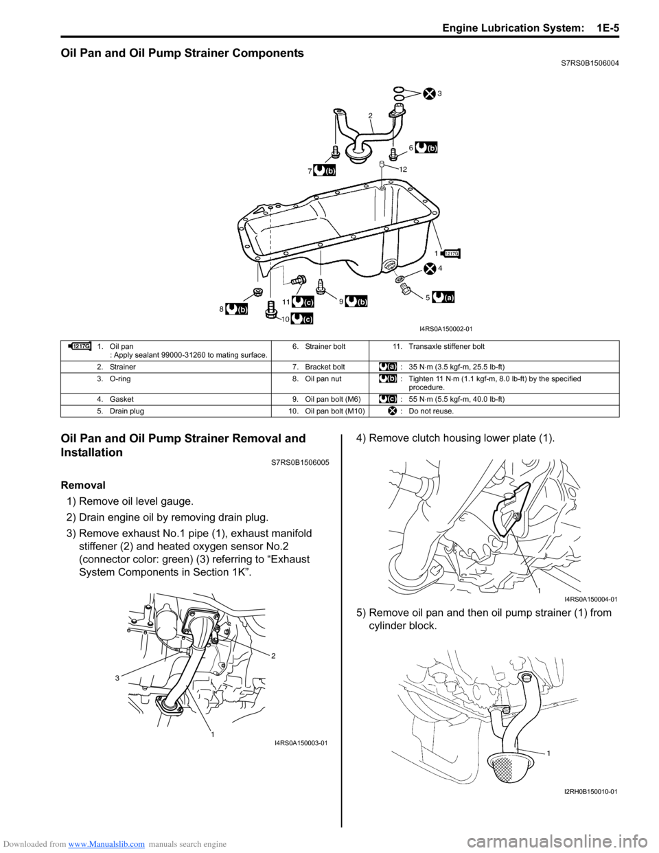
Oil Pan and Oil Pump Strainer ComponentsS7RS0B1506004
Oil Pan and Oil Pump Strainer Removal and
Installation
S7RS0B1506005
Removal1) Remove oil level gauge.
2) Drain engine oil by removing drain plug.
3) Remove exhaust No.1 pipe (1), exhaust manifold stiffener (2) and heated oxygen sensor No.2
(connector color: green) (3) referring to “Exhaust
System Components in Section 1K”. 4) Remove clutch housing lower plate (1).
5) Remove oil pan and then oil pump strainer (1) from
cylinder block.
I4RS0A150002-01
1. Oil pan : Apply sealant 99000-31260 to mating surface. 6. Strainer bolt 11. Transaxle stiffener bolt
2. Strainer 7. Bracket bolt : 35 N ⋅m (3.5 kgf-m, 25.5 lb-ft)
3. O-ring 8. Oil pan nut : Tighten 11 N ⋅m (1.1 kgf-m, 8.0 lb-ft) by the specified
procedure.
4. Gasket 9. Oil pan bolt (M6) : 55 N ⋅m (5.5 kgf-m, 40.0 lb-ft)
5. Drain plug 10. Oil pan bolt (M10) : Do not reuse.
2
1
3
I4RS0A150003-01
1I4RS0A150004-01
I2RH0B150010-01
Page 382 of 1496
Downloaded from www.Manualslib.com manuals search engine 1G-7 Fuel System:
Fuel Pressure Relief ProcedureS7RS0B1706003
CAUTION!
This work must not be done when engine is
hot. If done so, it may cause adverse effect to
catalyst.
NOTE
If ECM detects DTC(s) after servicing, clear
DTC(s) referring to “DTC Clearance in
Section 1A”.
1) Make sure that engine is cold.
2) Shift transaxle gear shift lever in “Neutral” (shift select lever in “P” range for A/T model), set parking
brake and block drive wheels.
3) Remove relay / fuse box cover.
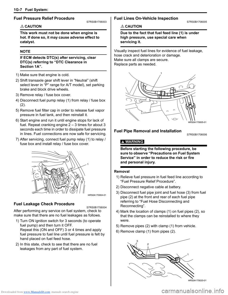
4) Disconnect fuel pump relay (1) from relay / fuse box (2).
5) Remove fuel filter cap in order to release fuel vapor pressure in fuel tank, and then reinstall it.
6) Start engine and run it until engine stops for lack of fuel. Repeat cranking engine 2 – 3 times for about 3
seconds each time in order to dissipate fuel pressure
in lines. Fuel connections are now safe for servicing.
7) After servicing, connect fuel pump relay (1) to relay / fuse box and install re lay / fuse box cover.
Fuel Leakage Check ProcedureS7RS0B1706004
After performing any service on fuel system, check to
make sure that there are no fuel leakages as follows.
1) Turn ON ignition switch for 3 seconds (to operate fuel pump) and then turn it OFF.
Repeat this (ON and OFF) 3 or 4 times and apply
fuel pressure to fuel line until fuel pressure is felt by
hand placed on fuel feed hose.
2) In this state, check to see that there are no fuel leakages from any part of fuel system.
Fuel Lines On-Vehicle InspectionS7RS0B1706005
CAUTION!
Due to the fact that fuel feed line (1) is under
high pressure, use special care when
servicing it.
Visually inspect fuel lines for evidence of fuel leakage,
hose crack and deterioration or damage.
Make sure all cl amps are secure.
Replace parts as needed.
Fuel Pipe Removal and InstallationS7RS0B1706006
WARNING!
Before starting the following procedure, be
sure to observe “Precautions on Fuel System
Service” in order to reduce the risk or fire
and personal injury.
Removal
1) Relieve fuel pressure in fuel feed line according to “Fuel Pressure Relief Procedure”.
2) Disconnect negative cable at battery.
3) Disconnect fuel pipe joint and fuel hose (3) from fuel pipe (2) at the front and rear of each fuel pipe
referring to “Fuel Hose Disconnecting and
Reconnecting”.
4) Mark the location of clamps (1) on fuel pipes (2), so that the clamps can be reinstalled to where they
were.
5) Remove pipes (2) with clamp (1) from vehicle.
6) Remove clamp (1) from pipes (2).
1
I4RS0A170004-01
1
I4RS0A170005-01
2
13
I4RS0A170020-01
Page 429 of 1496
Downloaded from www.Manualslib.com manuals search engine Table of Contents 2- i
2
Section 2
CONTENTS
Suspension
Precautions ................................................. 2-1
Precautions............................................................. 2-1
Precautions on Suspension .................................. 2-1
Suspension General Dia gnosis.............. 2A-1
Diagnostic Information and Procedures ............ 2A-1
Suspension, Wheels and Tires Symptom Diagnosis .......................................................... 2A-1
Front Suspension ........... ......................... 2B-1
General Description ............................................. 2B-1
Front Suspension Construction ........................... 2B-1
Front Wheel Alignment Cons truction .................. 2B-2
Repair Instructions .............................................. 2B-2 Front Wheel Alignment Inspection and Adjustment ........................................................ 2B-2
Front Strut Assembly Comp onents ..................... 2B-4
Front Strut Assembly Removal and Installation ......................................................... 2B-4
Front Strut Assembly Disassembly and Assembly .......................................................... 2B-6
Front Strut Assembly Chec k ............................... 2B-7
Front Wheel Hub and Steering Knuckle Components...................................................... 2B-8
Front Wheel Hub, Steering Knuckle and Wheel Bearing Removal and Installation .......... 2B-8
Front Wheel Hub, Disc, Nut and Bearing Check .............................................................. 2B-12
Suspension Control Arm / Bushing Removal and Installation ................................................ 2B-12
Suspension Control Arm / Bushing Disassembly and Assembly ............................ 2B-13
Suspension Control Arm / Steering Knuckle Check .............................................................. 2B-14
Suspension Control Arm Bushing Check .......... 2B-14
Suspension Control Arm Joint Check ............... 2B-14
Front Suspension Fram e, Stabilizer Bar and/
or Bushings Components................................ 2B-15
Front Suspension Fram e, Stabilizer Bar and/
or Bushings Removal and Installation ............. 2B-15
Front Suspension Frame Ch eck ....................... 2B-19
Front Stabilizer Bar, Bushing and/or Joint Check .............................................................. 2B-19
Front Suspension Fastener s Check .................. 2B-19
Specifications ..................................................... 2B-20 Tightening Torque Specifications ...................... 2B-20
Special Tools and Equipmen t ...........................2B-21
Special Tool ...................................................... 2B-21
Rear Suspension ............ ......................... 2C-1
General Description .............................................2C-1
Rear Suspension Construction ...........................2C-1
Repair Instructions ........... ...................................2C-2
Rear Wheel Alignment Inspection .......................2C-2
Rear Shock Absorber Removal and Installation .........................................................2C-2
Rear Shock Absorber Ins pection ........................2C-3
Rear Shock Absorber Bush Removal and Installation .........................................................2C-4
Rear Shock Absorber Bush Inspection ...............2C-4
Rear Coil Spring Removal and Installation .........2C-4
Spring Upper Seat / Spring Lower Seat Inspection ..........................................................2C-5
Spring Upper Seat and Lower Seat Removal and Installation ..................................................2C-6
Rear Axle Removal and Inst allation ....................2C-6
Trailing Arm, Rear Axle and Coil Spring Inspection ..........................................................2C-9
Rear Axle Bush Inspection ..................................2C-9
Rear Wheel Hub Components ..........................2C-10
Rear Wheel Hub Removal an d Installation .......2C-10
Rear Wheel Disc, bolt and Bearing Inspection ..2C-11
Spindle Removal and Installation ......................2C-12
Spindle Inspection .............................................2C-13
Rear Suspension Fasteners Inspection ............2C-13
Specifications .................... .................................2C-13
Tightening Torque Specifications ......................2C-13
Special Tools and Equipmen t ...........................2C-13
Special Tool ......................................................2C-13
Wheels and Tires ............ ......................... 2D-1
Precautions...........................................................2D-1
Precaution for Emergency Flat Tire Repair Kit ....2D-1
General Description .............................................2D-1 Tires Description .................................................2D-1
Wheels Description .............................................2D-2
Irregular and/or Premature Wear Description .....2D-3
Wear Indicators Description ................................2D-3
Radial Tire Waddle Description...........................2D-4
Radial Tire Lead / Pull Description ......................2D-5
Page 456 of 1496
Downloaded from www.Manualslib.com manuals search engine 2C-2 Rear Suspension:
Repair Instructions
Rear Wheel Alignment InspectionS7RS0B2306017
Measure toe and camber referring to “Front Wheel
Alignment Inspection and Adjustment in Section 2B”.
NOTE
Rear suspension is not adjustable structure.
Rear toe (total)
: IN 3.8 ± 3.8 mm (IN 0.1969 ± 0.1969 in)
Rear camber
: –1 ° ± 1
If measured value is out of specified value, check
following items for damage, deformation and crack.
• Rear axle (torsion beam)
• Spindle, wheel hub or wheel bearing
• Vehicle body
Rear Shock Absorber Removal and InstallationS7RS0B2306001
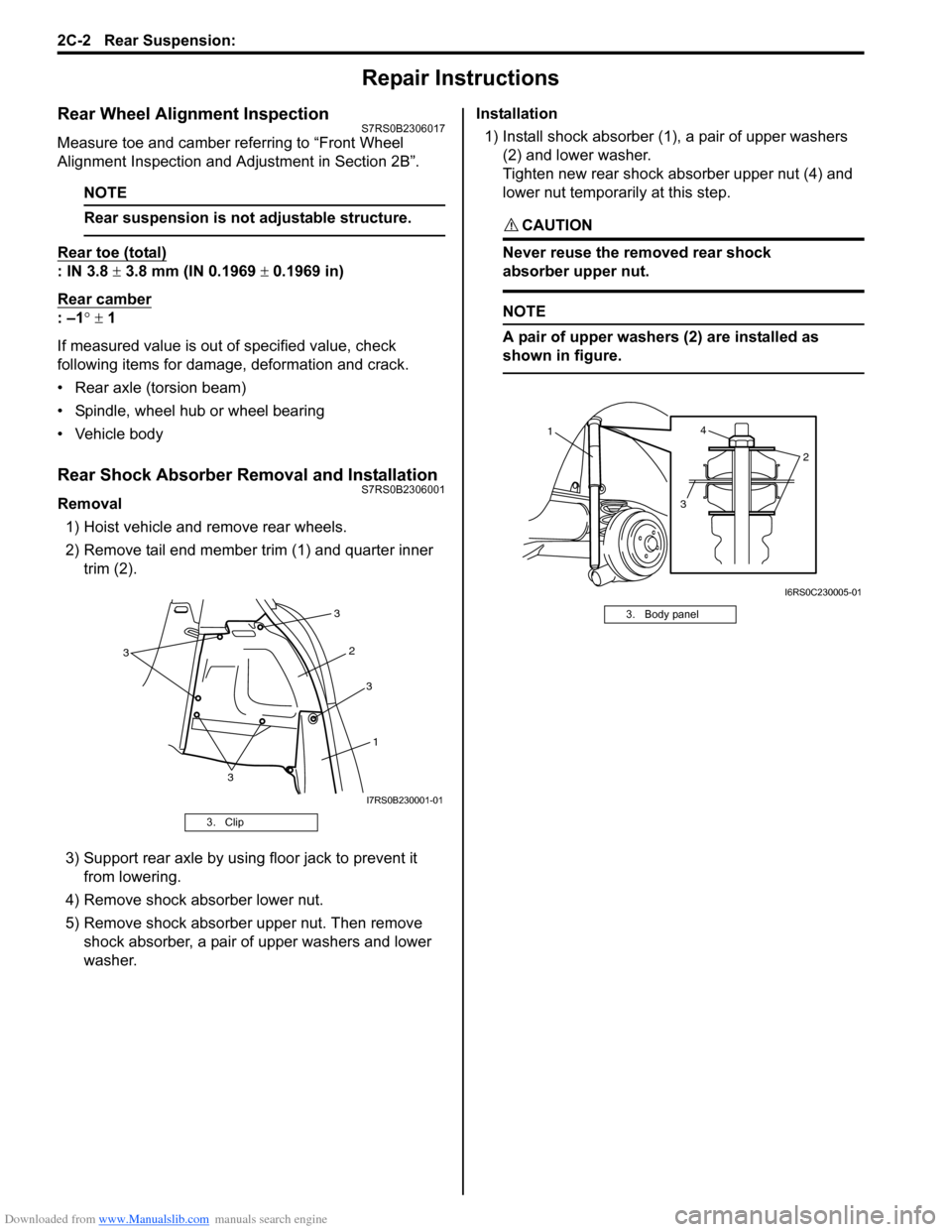
Removal 1) Hoist vehicle and remove rear wheels.
2) Remove tail end member trim (1) and quarter inner trim (2).
3) Support rear axle by using floor jack to prevent it from lowering.
4) Remove shock absorber lower nut.
5) Remove shock absorber upper nut. Then remove shock absorber, a pair of upper washers and lower
washer. Installation
1) Install shock absorber (1), a pair of upper washers (2) and lower washer.
Tighten new rear shock absorber upper nut (4) and
lower nut temporarily at this step.
CAUTION!
Never reuse the removed rear shock
absorber upper nut.
NOTE
A pair of upper washers (2) are installed as
shown in figure.
3. Clip
3
3 2
3
1
3
I7RS0B230001-01
3. Body panel
14
3 2
I6RS0C230005-01
Page 458 of 1496
Downloaded from www.Manualslib.com manuals search engine 2C-4 Rear Suspension:
Rear Shock Absorber Bush Removal and
Installation
S7RS0B2306003
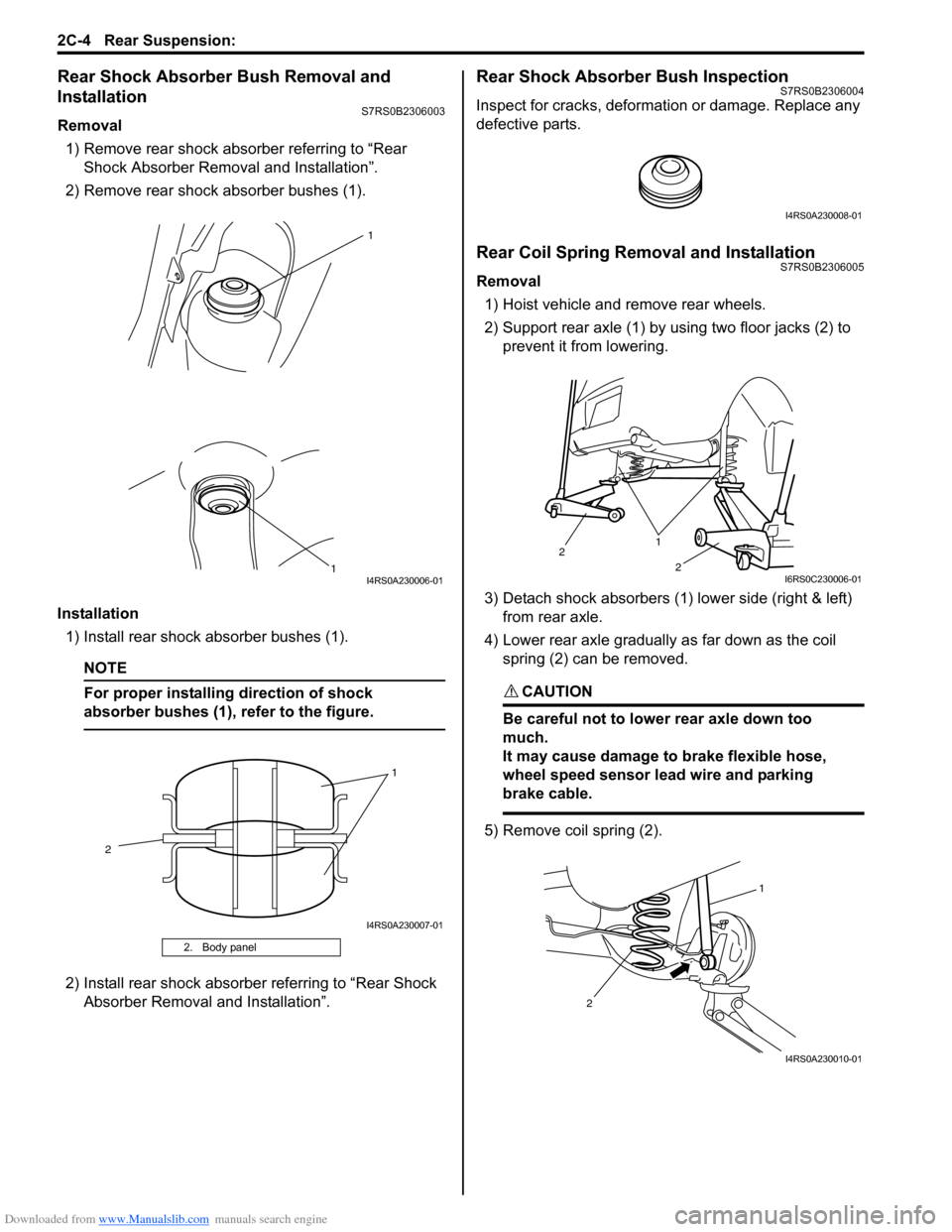
Removal1) Remove rear shock absorber referring to “Rear Shock Absorber Remova l and Installation”.
2) Remove rear shock absorber bushes (1).
Installation 1) Install rear shock absorber bushes (1).
NOTE
For proper installing direction of shock
absorber bushes (1), refer to the figure.
2) Install rear shock absorber referring to “Rear Shock Absorber Removal and Installation”.
Rear Shock Absorber Bush InspectionS7RS0B2306004
Inspect for cracks, deformation or damage. Replace any
defective parts.
Rear Coil Spring Removal and InstallationS7RS0B2306005
Removal
1) Hoist vehicle and remove rear wheels.
2) Support rear axle (1) by using two floor jacks (2) to prevent it from lowering.
3) Detach shock absorbers (1) lower side (right & left) from rear axle.
4) Lower rear axle gradually as far down as the coil spring (2) can be removed.
CAUTION!
Be careful not to lowe r rear axle down too
much.
It may cause damage to brake flexible hose,
wheel speed sensor lead wire and parking
brake cable.
5) Remove coil spring (2).
2. Body panel
1
1
I4RS0A230006-01
1
2
I4RS0A230007-01
I4RS0A230008-01
1
2
2
I6RS0C230006-01
1
2
I4RS0A230010-01