Drive SUZUKI SWIFT 2008 2.G Service Workshop Manual
[x] Cancel search | Manufacturer: SUZUKI, Model Year: 2008, Model line: SWIFT, Model: SUZUKI SWIFT 2008 2.GPages: 1496, PDF Size: 34.44 MB
Page 648 of 1496
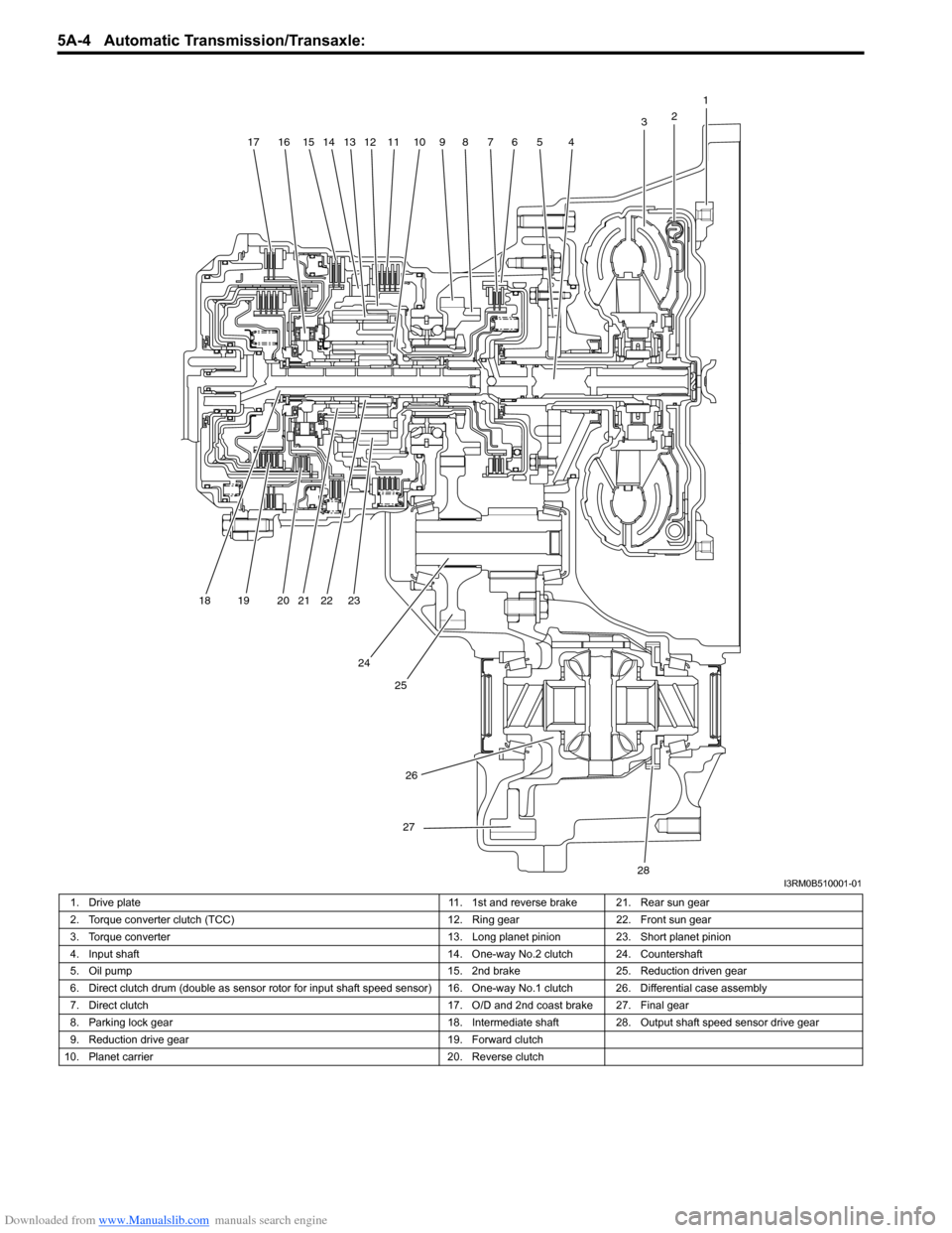
Downloaded from www.Manualslib.com manuals search engine 5A-4 Automatic Transmission/Transaxle:
1
2
3
4567891011121314151617
18 19 20 21 22 23
24 25
26
27
28I3RM0B510001-01
1. Drive plate 11. 1st and reverse brake 21. Rear sun gear
2. Torque converter clutch (TCC) 12. Ring gear22. Front sun gear
3. Torque converter 13. Long planet pinion23. Short planet pinion
4. Input shaft 14. One-way No.2 clutch 24. Countershaft
5. Oil pump 15. 2nd brake25. Reduction driven gear
6. Direct clutch drum (double as sensor ro tor for input shaft speed sensor) 16. One-way No.1 clutch 26. Differential case assembly
7. Direct clutch 17. O/D and 2nd coast brake 27. Final gear
8. Parking lock gear 18. Intermediate shaft28.Output shaft speed sensor drive gear
9. Reduction drive gear 19. Forward clutch
10. Planet carrier 20. Reverse clutch
Page 649 of 1496
Downloaded from www.Manualslib.com manuals search engine Automatic Transmission/Transaxle: 5A-5
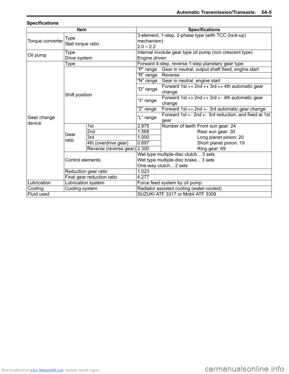
SpecificationsItem Specifications
Torque converter Ty p e
Stall torque ratio 3-element, 1-step, 2-phase type (with TCC (lock-up)
mechanism)
2.0 – 2.2
Oil pump Ty p e
Drive system Internal involute gear type oil pump (non crescent type)
Engine driven
Gear change
device Type Forward 4-step, reverse 1-step planetary gear type
Shift position
“P” range Gear in neutral, output shaft fixed, engine start
“R” range Reverse
“N” range Gear in neutral, engine start
“D” range
Forward 1st
↔ 2nd ↔ 3rd ↔ 4th automatic gear
change
“3” range Forward 1st
↔ 2nd ↔ 3rd ← 4th automatic gear
change
“2” range Forward 1st ↔ 2nd ← 3rd automatic gear change
“L” range Forward 1st
← 2nd ← 3rd reduction, and fixed at 1st
gear
Gear
ratio 1st 2.875 Number of teeth Front sun gear: 24
2nd 1.568 Rear sun gear: 30
3rd 1.000 Long planet pinion: 20
4th (overdrive gear) 0.697 Short planet pinion: 19
Reverse (reverse gear) 2.300 Ring gear: 69
Control elements Wet type multiple-disc clutch... 3 sets
Wet type multiple-d
isc brake... 3 sets
One-way clutch... 2 sets
Reduction gear ratio 1.023
Final gear reduction ratio 4.277
Lubrication Lubrication system Force feed system by oil pump
Cooling Cooling system Radiator assisted cooling (water-cooled)
Fluid used SUZUKI ATF 3317 or Mobil ATF 3309
Page 650 of 1496
Downloaded from www.Manualslib.com manuals search engine 5A-6 Automatic Transmission/Transaxle:
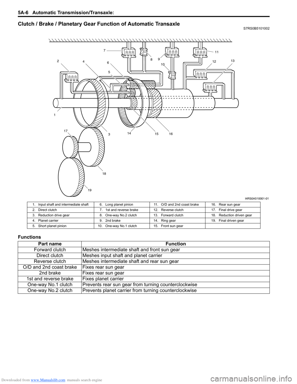
Clutch / Brake / Planetary Gear Function of Automatic TransaxleS7RS0B5101002
Functions
12
4
3 5
6
7
89
10 11
12 13
14 15 16
17
18
19
I4RS0A510001-01
1. Input shaft and intermediate shaft 6. Long planet pi nion 11. O/D and 2nd coast brake 16. Rear sun gear
2. Direct clutch 7. 1st and reverse brak e 12. Reverse clutch 17. Final drive gear
3. Reduction drive gear 8. One-way No.2 clutch 13. Forward clutch 18. Reduction driven gear
4. Planet carrier 9. 2nd brake 14. Ring gear 19. Final driven gear
5. Short planet pinion 10. One-way No.1 clutch 15. Front sun gear
Part name Function
Forward clutch Meshes intermediate shaft and front sun gear Direct clutch Meshes input shaft and planet carrier
Reverse clutch Meshes intermediate shaft and rear sun gear
O/D and 2nd coast brake Fixes rear sun gear 2nd brake Fixes rear sun gear
1st and reverse brake Fixes planet carrier One-way No.1 clutch Prevents rear sun gear from turning counterclockwise
One-way No.2 clutch Prevents planet ca rrier from turning counterclockwise
Page 654 of 1496
Downloaded from www.Manualslib.com manuals search engine 5A-10 Automatic Transmission/Transaxle:
Schematic and Routing Diagram
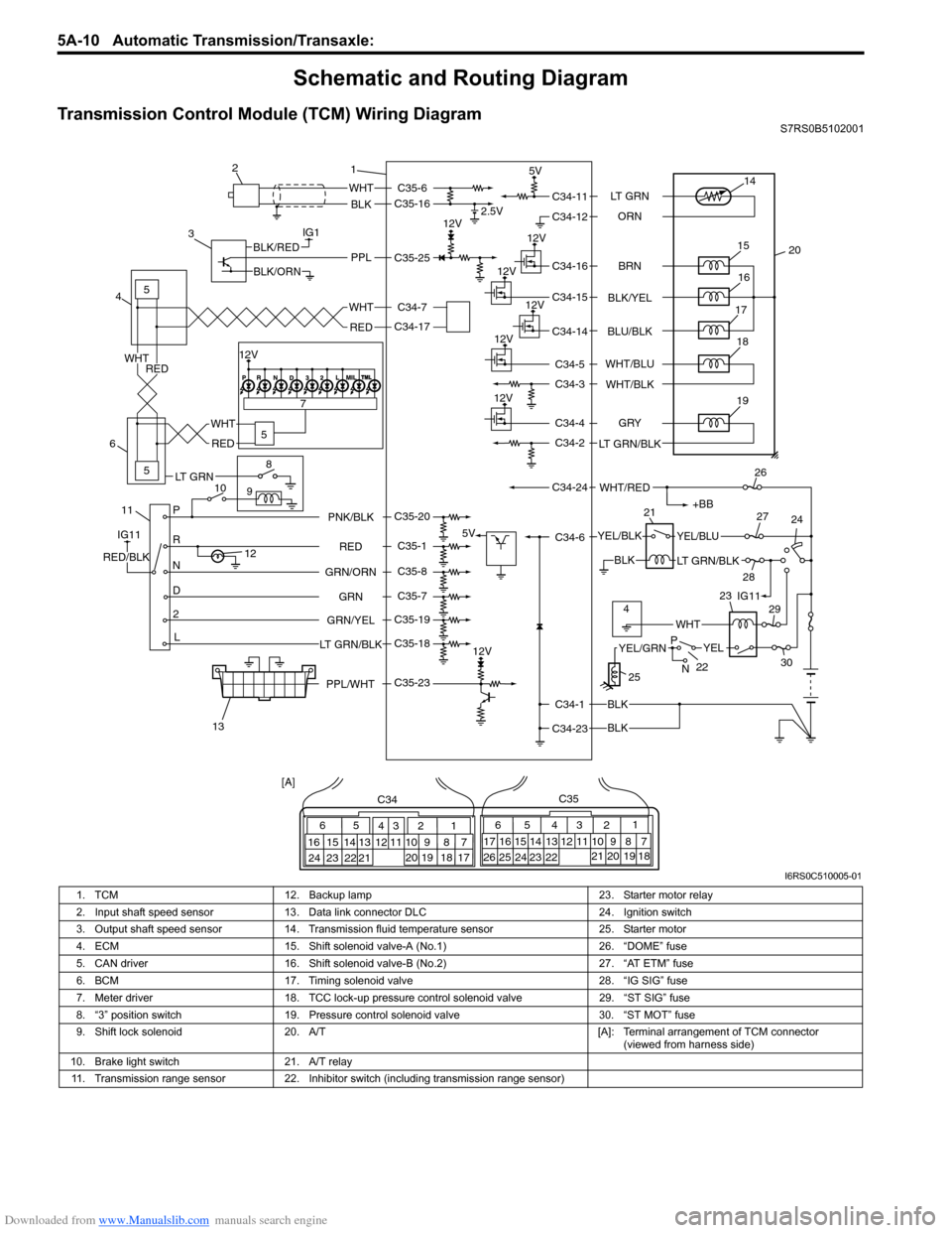
Transmission Control Module (TCM) Wiring DiagramS7RS0B5102001
IG1
115
5
5
8
9
10 7
P
R
N
D
2
L
12
12V 2.5V
5V
12V
5V
12V
12V
12V
12V
WHT
BLK
BLK
BLK
BLK
PPLBLK/RED
BLK/ORN
IG11
RED/BLK
YEL/BLKYEL/BLU
LT GRN/BLK
+BB
WHT/RED
14
20
15
16
17
19
12V18
1
2
3
4
6
13 21
26
24
27
28 29
30
WHT
WHT
RED
RED
WHT
RED
65
16 15 14 13 12 11 43
24 23 2122 10 9 8 721
1920 18 17
C34
17 16
26 25
15 14
65 3
42
13 12
23 2224 11 10 9
21 20 19 87
18
1
C35
[A]
22
25
YELYEL/GRN
WHT
P
N
BRN
LT GRN
ORN
BLK/YEL
BLU/BLK
GRY
LT GRN/BLK WHT/BLU
WHT/BLK
C34-11
C34-12
C34-16
C34-15
C34-14
C34-4
C34-2
C34-1
C34-23 C34-6
C34-24 C34-5
C34-3
RED
GRN
GRN/ORN PNK/BLK
GRN/YEL
LT GRN/BLKC35-6
C35-16
C35-23 C35-25
C35-20
C35-1
C35-8
C35-7
C35-19
C35-18 C34-17 C34-7
4IG11
12V
23
PPL/WHT
LT GRN
I6RS0C510005-01
1. TCM 12. Backup lamp 23. Starter motor relay
2. Input shaft speed sensor 13. Data link connector DLC 24. Ignition switch
3. Output shaft speed sensor 14. Transmission fluid temperature sensor 25. Starter motor
4. ECM 15. Shift solenoid valve-A (No.1) 26. “DOME” fuse
5. CAN driver 16. Shift solenoid valve-B (No.2) 27. “AT ETM” fuse
6. BCM 17. Timing solenoid valve 28. “IG SIG” fuse
7. Meter driver 18. TCC lock-up pressure control solenoid valve 29. “ST SIG” fuse
8. “3” position switch 19. Pressure control solenoid valve 30. “ST MOT” fuse
9. Shift lock solenoid 20. A/T [A]: Terminal arrangement of TCM connector
(viewed from harness side)
10. Brake light switch 21. A/T relay
11. Transmission range sensor 22. Inhibitor switch (including transmission range sensor)
Page 656 of 1496
Downloaded from www.Manualslib.com manuals search engine 5A-12 Automatic Transmission/Transaxle:
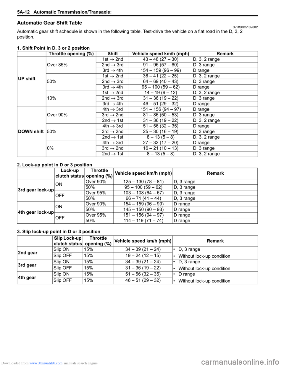
Automatic Gear Shift TableS7RS0B5102002
Automatic gear shift schedule is shown in the following table. Test-drive the vehicle on a flat road in the D, 3, 2
position.
1. Shift Point in D, 3 or 2 position
2. Lock-up point in D or 3 position
3. Slip lock-up point in D or 3 position Throttle opening (%) Shift Vehicle speed km/h (mph) Remark
UP shift Over 85%
1st →
2nd 43 – 48 (27 – 30) D, 3, 2 range
2nd → 3rd 91 – 96 (57 – 60) D, 3 range
3rd → 4th 154 – 159 (96 – 99) D range
50% 1st →
2nd 36 – 41 (22 – 25) D, 3, 2 range
2nd → 3rd 64 – 69 (40 – 43) D, 3 range
3rd → 4th 95 – 100 (59 – 62) D range
10% 1st →
2nd 14 – 19 (9 – 12) D, 3, 2 range
2nd → 3rd 31 – 36 (19 – 22) D, 3 range
3rd → 4th 46 – 51 (29 – 32) D range
DOWN shift Over 90%
4th
→ 3rd 151 – 156 (94 – 97) D range
3rd → 2nd 81 – 86 (50 – 53) D, 3 range
2nd → 1st 31 – 36 (19 – 22) D, 3, 2 range
50% 4th
→ 3rd 51 – 56 (32 – 35) D range
3rd → 2nd 25 – 30 (16 – 19) D, 3 range
2nd → 1st 8 – 13 (5 – 8) D, 3, 2 range
0% 4th
→ 3rd 27 – 32 (17 – 20) D range
3rd → 2nd 16 – 21 (10 – 13) D, 3 range
2nd → 1st 8 – 13 (5 – 8) D, 3, 2 range
Lock-up
clutch status Throttle
opening (%) Vehicle speed km/h (mph) Remark
3rd gear lock-up ON
Over 90% 125 – 130 (78 – 81) D, 3 range
50% 95 – 100 (59 – 62) D, 3 range
OFF Over 95% 103 – 108 (64 – 67) D, 3 range
50% 66 – 71 (41 – 44) D, 3 range
4th gear lock-up ON
Over 90% 154 – 159 (96 – 99) D range
50% 145 – 150 (90 – 93) D range
OFF Over 95% 151 – 156 (94 – 97) D range
50% 114 – 119 (71 – 74) D range
Slip Lock-up
clutch status Throttle
opening (%) Vehicle speed km/h (mph) Remark
2nd gear Slip ON 15% 34 – 39 (21 – 24) • D, 3 range
• Without lock-up condition
Slip OFF 15% 19 – 24 (12 – 15)
3rd gear Slip ON 15% 34 – 39 (21 – 24) • D, 3 range
• Without lock-up condition
Slip OFF 15% 31 – 36 (19 – 22)
4th gear Slip ON 15% 51 – 56 (32 – 35) • D range
• Without lock-up condition
Slip OFF 15% 46 – 51 (29 – 32)
Page 662 of 1496

Downloaded from www.Manualslib.com manuals search engine 5A-18 Automatic Transmission/Transaxle:
Visual InspectionS7RS0B5104002
Visually check the following parts and systems.
Malfunction Indicator Lamp (MIL) CheckS7RS0B5104003
Refer to the same item in “Malfunction Indicator Lam p (MIL) Check in Section 1A” for checking procedure.
Transmission Warning Light CheckS7RS0B5104004
1) Turn ignition switch ON.
2) Check that transmission warning light lights for about 2 – 4 sec. and then goes OFF.
If anything faulty is found, advance “Transmission Warn ing Light Circuit Check – Light Does Not Come “ON” at
Ignition Switch ON” or “Transmission Warning Light Circu it Check – Light Remains “ON” at Ignition Switch ON”.
Inspection item Referring
• A/T fluid ----- level, leakage, color “Automatic Transaxle Fluid Level Inspection in Section 0B”
• A/T fluid hoses ----- disconnection, looseness, deterioration “A/T Fluid Cooler Hoses Replacement”
• A/T select cable ----- installation “S elect Cable Removal and Installation”
• Engine oil ----- level, leakage “Engine Oil and Filter Change in Section 0B”
• Engine coolant ----- level, leakage “Engine Coolant Change in Section 0B”
• Engine mountings ----- play, looseness, damage “Engine Assembly Removal and Installation in Section 1D”
• Suspension ----- play, looseness “Suspension, Wheels and Tires Symptom Diagnosis in Section 2A”
• Drive shafts ----- damage “Front Drive Shaft Assembly On-Vehicle Inspection in Section 3A”
• Battery ----- indicator condition, corrosion of terminal “Battery Inspection in Section 1J”
• Connectors of electric wire harness ----- disconnection, friction “Electronic Shift Control System Components
Location”
• Fuses ----- burning
• Parts ----- installation, damage
• Bolts ----- looseness
• Other parts that can be checked visually
Also check the following items at engine start, if possible.
• Transmission warning light (if equipped) ----- Operation “Transmission Warning Light Check”
• Malfunction indicator lamp ----- Operation “Malfunction Indicator Lamp (MIL) Check”
• Charge warning lamp ----- Operation “Generator Symptom Diagnosis in Section 1J”
• Engine oil pressure warning lamp ----- Operation “Oil Pressure Warning Ligh t Symptom Diagnosis in
Section 9C”
• Engine coolant temp. meter ----- Operation “Engine Coolant Temperature (ECT) Meter
Symptom Diagnosis in Section 9C”
• Other parts that can be checked visually
I4RS0A510008-01
Page 665 of 1496
Downloaded from www.Manualslib.com manuals search engine Automatic Transmission/Transaxle: 5A-21
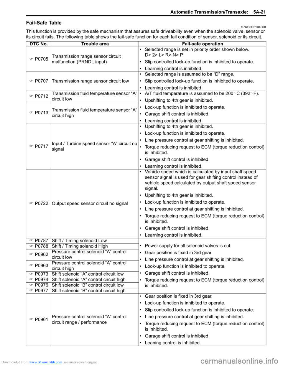
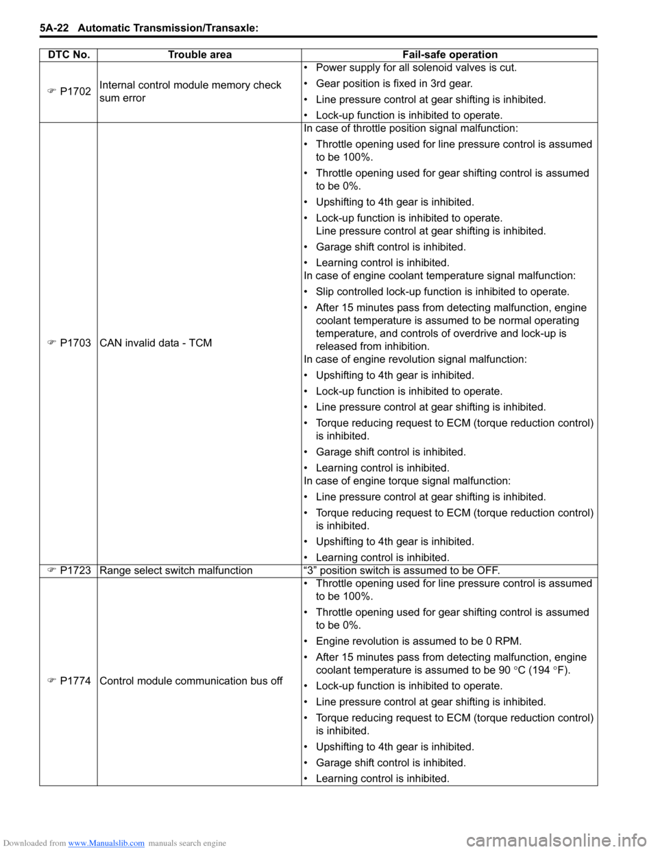
Fail-Safe TableS7RS0B5104008
This function is provided by the safe mechanism that assures safe driveability even when the solenoid valve, sensor or
its circuit fails. The following table shows th e fail-safe function for each fail condition of sensor, solenoid or its circuit.
DTC No. Trouble area Fail-safe operation
�) P0705 Transmission range sensor circuit
malfunction (PRNDL input) • Selected range is set in priority order shown below.
D> 2> L> R> N> P
• Slip controlled lock-up function is inhibited to operate.
• Learning control is inhibited.
�) P0707 Transmission range sensor circuit low • Selected range is assumed to be “D” range.
• Slip controlled lock-up function is inhibited to operate.
• Learning control is inhibited.
�) P0712 Transmission fluid temperature sensor “A”
circuit low • A/T fluid temperature is assumed to be 200
°C (392 °F).
• Upshifting to 4th gear is inhibited.
• Lock-up function is inhibited to operate.
• Garage shift control is inhibited.
• Learning control is inhibited.
�)
P0713 Transmission fluid temperature sensor “A”
circuit high
�) P0717 Input / Turbine speed sensor “A” circuit no
signal • Upshifting to 4th gear is inhibited.
• Lock-up function is inhibited to operate.
• Line pressure control at gear shifting is inhibited.
• Torque reducing request to ECM (torque reduction control)
is inhibited.
• Garage shift control is inhibited.
• Learning control is inhibited.
�) P0722 Output speed sensor circuit no signal • Vehicle speed which is calculated by input shaft speed
sensor signal is used for gear shifting control instead of
vehicle speed calculated by output shaft speed sensor
signal.
• Upshifting to 4th gear is inhibited.
• Lock-up function is inhibited to operate.
• Line pressure control at gear shifting is inhibited.
• Torque reducing request to ECM (torque reduction control) is inhibited.
• Garage shift control is inhibited.
• Learning control is inhibited.
�) P0787 Shift / Timing solenoid Low
• Power supply for all solenoid valves is cut.
• Gear position is fixed in 3rd gear.
• Line pressure control at gear shifting is inhibited.
• Look-up function is inhibited to operate.
• Garage shift control is inhibited.
• Torque reducing request to ECM (torque reduction control)
is inhibited.
�)
P0788 Shift / Timing solenoid High
�) P0962 Pressure control solenoid “A” control
circuit low
�) P0963 Pressure control solenoid “A” control
circuit high
�) P0973 Shift solenoid “A” control circuit low
�) P0974 Shift solenoid “A” control circuit high
�) P0976 Shift solenoid “B” control circuit low
�) P0977 Shift solenoid “B” control circuit high
�) P0961 Pressure control solenoid “A” control
circuit range / performance • Gear position is fixed in 3rd gear.
• Lock-up function is inhibited to operate.
• Slip controlled lock-up function is inhibited to operate.
• Line pressure control at gear shifting is inhibited.
• Torque reducing request to ECM (torque reduction control)
is inhibited.
• Garage shift control is inhibited.
• Leaning control is inhibited.
Page 666 of 1496
Downloaded from www.Manualslib.com manuals search engine 5A-22 Automatic Transmission/Transaxle:
�) P1702 Internal control module memory check
sum error • Power supply for all solenoid valves is cut.
• Gear position is fixed in 3rd gear.
• Line pressure control at gear shifting is inhibited.
• Lock-up function is inhibited to operate.
�) P1703 CAN invalid data - TCM In case of throttle position signal malfunction:
• Throttle opening used for line pressure control is assumed
to be 100%.
• Throttle opening used for gear shifting control is assumed to be 0%.
• Upshifting to 4th gear is inhibited.
• Lock-up function is inhibited to operate. Line pressure control at gear shifting is inhibited.
• Garage shift control is inhibited.
• Learning control is inhibited.
In case of engine coolant temperature signal malfunction:
• Slip controlled lock-up function is inhibited to operate.
• After 15 minutes pass from detecting malfunction, engine coolant temperature is assumed to be normal operating
temperature, and controls of overdrive and lock-up is
released from inhibition.
In case of engine revolution signal malfunction:
• Upshifting to 4th gear is inhibited.
• Lock-up function is inhibited to operate.
• Line pressure control at gear shifting is inhibited.
• Torque reducing request to ECM (torque reduction control) is inhibited.
• Garage shift control is inhibited.
• Learning control is inhibited.
In case of engine torque signal malfunction:
• Line pressure control at gear shifting is inhibited.
• Torque reducing request to ECM (torque reduction control) is inhibited.
• Upshifting to 4th gear is inhibited.
• Learning control is inhibited.
�) P1723 Range select switch malfunction “3” position switch is assumed to be OFF.
�) P1774 Control module communication bus off • Throttle opening used for line pressure control is assumed
to be 100%.
• Throttle opening used for gear shifting control is assumed to be 0%.
• Engine revolution is assumed to be 0 RPM.
• After 15 minutes pass from detecting malfunction, engine coolant temperature is assumed to be 90 °C (194 °F).
• Lock-up function is inhibited to operate.
• Line pressure control at gear shifting is inhibited.
• Torque reducing request to ECM (torque reduction control) is inhibited.
• Upshifting to 4th gear is inhibited.
• Garage shift control is inhibited.
• Learning control is inhibited.
DTC No. Trouble area Fail-safe operation
Page 671 of 1496
Downloaded from www.Manualslib.com manuals search engine Automatic Transmission/Transaxle: 5A-27
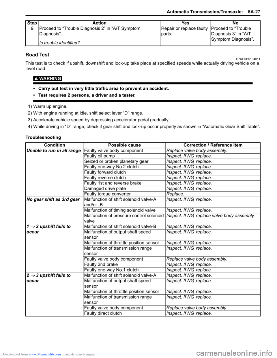
Road TestS7RS0B5104011
This test is to check if upshift, downshift and lock-up take place at specified speeds while actually driving vehicle on a
level road.
WARNING!
• Carry out test in very little traffic area to prevent an accident.
• Test requires 2 persons, a driver and a tester.
1) Warm up engine.
2) With engine running at idle, shift select lever “D” range.
3) Accelerate vehicle speed by depressing accelerator pedal gradually.
4) While driving in “D” range, check if gear shift and lock-up occur properly as shown in “Automatic Gear Shift Table”.
Troubleshooting 9 Proceed to “Trouble Diag
nosis 2” in “A/T Symptom
Diagnosis”.
Is trouble identified? Repair or replace faulty
parts.
Proceed to “Trouble
Diagnosis 3” in “A/T
Symptom Diagnosis”.
Step Action Yes No
Condition
Possible cause Correction / Reference Item
Unable to run in all range Faulty valve body component Replace valve body assembly.
Faulty oil pump Inspect. If NG, replace.
Seized or broken planetary gear Inspect. If NG, replace.
Faulty one-way No.2 clutch Inspect. If NG, replace.
Faulty forward clutch Inspect. If NG, replace.
Faulty reverse clutch Inspect. If NG, replace.
Faulty 1st and reverse brake Inspect. If NG, replace.
Damaged drive plate Inspect. If NG, replace.
Faulty torque converter Replace.
No gear shift as 3rd gear Malfunction of shift solenoid valve-A
and/or -B Inspect. If NG, replace.
Malfunction of timing solenoid valve Inspect. If NG, replace.
Malfunction of pressure control solenoid
valve Inspect. If NG, replace valve body assembly.
1
→ 2 upshift fails to
occur Malfunction of shif
t solenoid valve-B Inspect. If NG, replace.
Malfunction of output shaft speed
sensor Inspect. If NG, replace.
Malfunction of throttle position sensor Inspect. If NG, replace.
Malfunction of transmission range
sensor Inspect. If NG, replace.
Faulty valve body component Replace valve body assembly.
Faulty 2nd brake Inspect. If NG, replace.
Faulty one-way No.1 clutch Inspect. If NG, replace.
2
→ 3 upshift fails to
occur Malfunction of shif
t solenoid valve-A Inspect. If NG, replace.
Malfunction of output shaft speed
sensor Inspect. If NG, replace.
Malfunction of throttle position sensor Inspect. If NG, replace.
Malfunction of transmission range
sensor Inspect. If NG, replace.
Faulty valve body component Replace valve body assembly.
Faulty direct clutch Inspect. If NG, replace.
Page 673 of 1496
Downloaded from www.Manualslib.com manuals search engine Automatic Transmission/Transaxle: 5A-29
Manual Road TestS7RS0B5104012
WARNING!
Carry out test in very little traffic area to prevent an accident.
Test requires 2 persons, a driver and a tester.
The purpose of this test is to judge whether causal factor of trouble which occurred in automatic transaxle is electrical
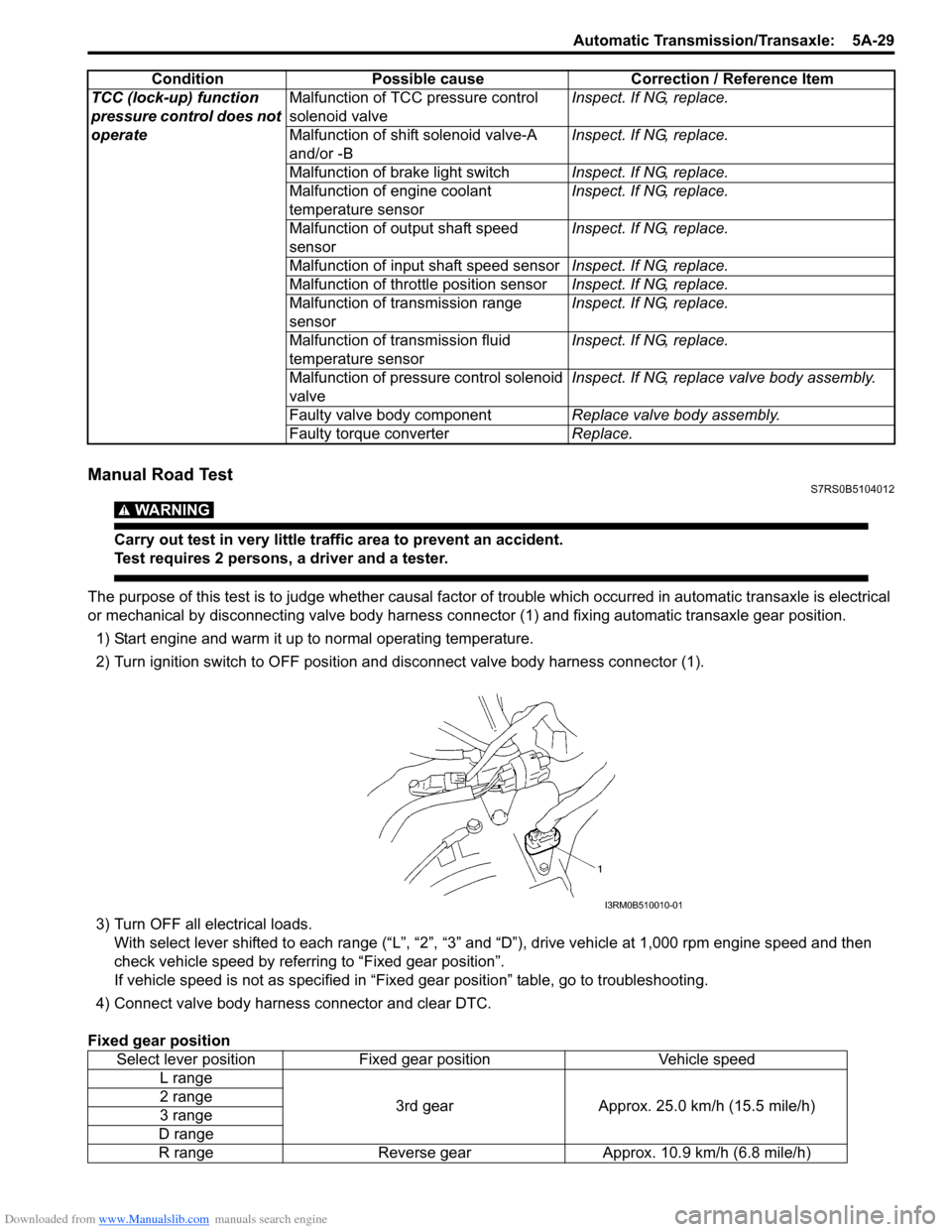
or mechanical by disconnecting valve body harness co nnector (1) and fixing automatic transaxle gear position.
1) Start engine and warm it up to normal operating temperature.
2) Turn ignition switch to OFF position and disconnect valve body harness connector (1).
3) Turn OFF all electrical loads. With select lever shifted to each ra nge (“L”, “2”, “3” and “D”), drive vehi cle at 1,000 rpm engine speed and then
check vehicle speed by referring to “Fixed gear position”.
If vehicle speed is not as specified in “Fix ed gear position” table, go to troubleshooting.
4) Connect valve body harness connector and clear DTC.
Fixed gear position TCC (lock-up) function
pressure control does not
operate
Malfunction of TCC pressure control
solenoid valve
Inspect. If NG, replace.
Malfunction of shif t solenoid valve-A
and/or -B Inspect. If NG, replace.
Malfunction of brake light switch Inspect. If NG, replace.
Malfunction of engine coolant
temperature sensor Inspect. If NG, replace.
Malfunction of output shaft speed
sensor Inspect. If NG, replace.
Malfunction of input shaft speed sensor Inspect. If NG, replace.
Malfunction of throttle position sensor Inspect. If NG, replace.
Malfunction of transmission range
sensor Inspect. If NG, replace.
Malfunction of transmission fluid
temperature sensor Inspect. If NG, replace.
Malfunction of pressure control solenoid
valve Inspect. If NG, replace valve body assembly.
Faulty valve body component Replace valve body assembly.
Faulty torque converter Replace.
Condition
Possible cause Correction / Reference Item
Select lever positionFixed gear position Vehicle speed
L range
3rd gearApprox. 25.0 km/h (15.5 mile/h)
2 range
3 range
D range
R range Reverse gear Approx. 10.9 km/h (6.8 mile/h)
I3RM0B510010-01