hot air SUZUKI SWIFT 2008 2.G Service Owner's Manual
[x] Cancel search | Manufacturer: SUZUKI, Model Year: 2008, Model line: SWIFT, Model: SUZUKI SWIFT 2008 2.GPages: 1496, PDF Size: 34.44 MB
Page 1042 of 1496
Downloaded from www.Manualslib.com manuals search engine 8B-4 Air Bag System:
WARNING!
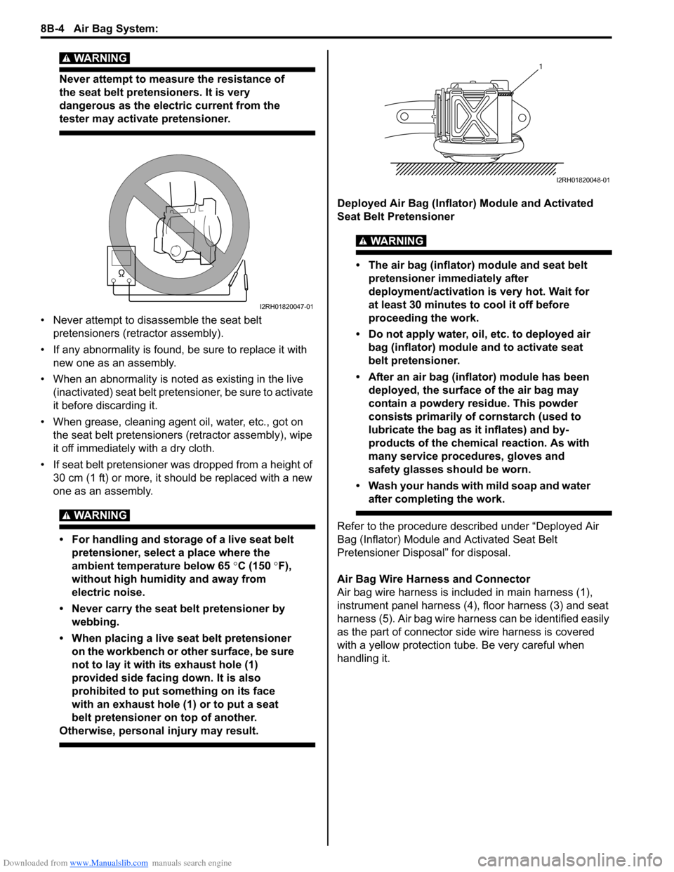
Never attempt to measure the resistance of
the seat belt pretensioners. It is very
dangerous as the electric current from the
tester may activate pretensioner.
• Never attempt to disassemble the seat belt
pretensioners (retractor assembly).
• If any abnormality is found, be sure to replace it with
new one as an assembly.
• When an abnormality is noted as existing in the live (inactivated) seat belt preten sioner, be sure to activate
it before discarding it.
• When grease, cleaning agent oil, water, etc., got on the seat belt pretensioners (r etractor assembly), wipe
it off immediately with a dry cloth.
• If seat belt pretensioner was dropped from a height of 30 cm (1 ft) or more, it should be replaced with a new
one as an assembly.
WARNING!
• For handling and storage of a live seat belt pretensioner, select a place where the
ambient temperature below 65 °C (150 ° F),
without high humidity and away from
electric noise.
• Never carry the seat belt pretensioner by webbing.
• When placing a live seat belt pretensioner on the workbench or other surface, be sure
not to lay it with its exhaust hole (1)
provided side facing down. It is also
prohibited to put something on its face
with an exhaust hole (1) or to put a seat
belt pretensioner on top of another.
Otherwise, personal injury may result.
Deployed Air Bag (Inflator) Module and Activated
Seat Belt Pretensioner
WARNING!
• The air bag (inflator) module and seat belt
pretensioner immediately after
deployment/activation is very hot. Wait for
at least 30 minutes to cool it off before
proceeding the work.
• Do not apply water, oil, etc. to deployed air bag (inflator) module and to activate seat
belt pretensioner.
• After an air bag (inflator) module has been deployed, the surface of the air bag may
contain a powdery residue. This powder
consists primarily of cornstarch (used to
lubricate the bag as it inflates) and by-
products of the chemical reaction. As with
many service procedures, gloves and
safety glasses should be worn.
• Wash your hands with mild soap and water after completing the work.
Refer to the procedure described under “Deployed Air
Bag (Inflator) Module and Activated Seat Belt
Pretensioner Disposal” for disposal.
Air Bag Wire Harness and Connector
Air bag wire harness is includ ed in main harness (1),
instrument panel harness (4), floor harness (3) and seat
harness (5). Air bag wire harness can be identified easily
as the part of connector side wire harness is covered
with a yellow protection tube. Be very careful when
handling it.
I2RH01820047-01
1
I2RH01820048-01
Page 1158 of 1496
Downloaded from www.Manualslib.com manuals search engine 8B-120 Air Bag System:
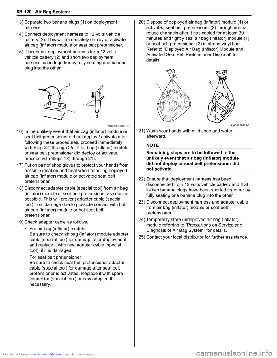
13) Separate two banana plugs (1) on deployment harness.
14) Connect deployment harness to 12 volts vehicle battery (2). This will immedi ately deploy or activate
air bag (inflator) module or seat belt pretensioner.
15) Disconnect deployment harness from 12 volts vehicle battery (2) and short two deployment
harness leads together by fully seating one banana
plug into the other.
16) In the unlikely event that air bag (inflator) module or seat belt pretensioner did not deploy / activate after
following these procedur es, proceed immediately
with Step 22) through 25). If air bag (inflator) module
or seat belt pretensioner did deploy or activate,
proceed with Steps 18) through 21).
17) Put on pair of shop gloves to protect your hands from possible irritation and heat when handling deployed
air bag (inflator) module or activated seat belt
pretensioner.
18) Disconnect adapter cable (special tool) from air bag (inflator) module or seat belt pretensioner as soon as
possible. This will preven t adapter cable (special
tool) from damage due to possible contact with hot
air bag (inflator) module or hot seat belt
pretensioner.
19) Check adapter cable as follows. • For air bag (inflator) moduleBe sure to check air bag (inflator) module adapter
cable (special tool) for damage after deployment
and replace it with new adapter cable (special
tool), if it is damaged.
• For seat belt pretensioner Be sure to check seat belt pretensioner adapter
cable (special tool) for damage after seat belt
pretensioner is activated. Replace it with spare
connector (special tool) or new adapter, if
necessary. 20) Dispose of deployed air bag (inflator) module (1) or
activated seat belt preten sioner (2) through normal
refuse channels after it has cooled for at least 30
minutes and tightly seal air bag (inflator) module (1)
or seat belt pretensioner (2) in strong vinyl bag.
Refer to “Deployed Air B ag (Inflator) Module and
Activated Seat Belt Pretensioner Disposal” for
details.
21) Wash your hands with mild soap and water afterward.
NOTE
Remaining steps are to be followed in the
unlikely event that air bag (inflator) module
did not deploy or seat belt pretensioner did
not activate.
22) Ensure that deployment harness has been disconnected from 12 volts vehicle battery and that
its two banana plugs have been shorted together by
fully seating one banana plug into the other.
23) Disconnect deployment harness and adapter cable from air bag (inflator) module or seat belt
pretensioner.
24) Temporarily store undeployed air bag (inflator) module referring to “Precautions on Service and
Diagnosis of Air Bag System” for details.
25) Contact your local distributor for further assistance.
I2RH01820069-01I3JA01820116-01
Page 1162 of 1496
Downloaded from www.Manualslib.com manuals search engine 8B-124 Air Bag System:
21) Disconnect adapter cable (special tool) from air bag (inflator) module or seat belt pretensioner as soon as
possible. This will preven t adapter cable (special
tool) from damage due to possible contact with hot
air bag (inflator) module or hot seat belt
pretensioner.
22) Check adapter cable connector as follows. Adapter cable connector (special tool) is designed to
be reused. However it should be inspected for
damage after deployment and replaced if necessary.
23) With air bag (inflator) modules deployed and seat belt pretensioners acti vated, vehicle may be
scrapped in the same manner as non-air bag system
/ seat belt pretensioner equipped vehicle.
NOTE
Remaining steps are to be followed in the
unlikely event that air bag (inflator) module
did not deploy or seat belt pretensioner did
not activate.
24) Remove undeployed air bag (inflator) module(s) and/ or inactivated seat belt pretensioner(s) from vehicle.
For driver air bag (inflator) module, refer to “Driver
Air Bag (Inflator) Module Removal and Installation”.
For passenger air bag (inflator) module, refer to
“Passenger Air Bag (Inflator) Module Removal and
Installation”. For seat belt pretensioner, refer to
“Front Seat Belt Removal an d Installation in Section
8A”.
25) Temporarily store undeployed air bag (inflator) module referring to “Precautions on Service and
Diagnosis of Air Bag System” for details.
26) Contact your local distribu tor for further assistance.
Deployed Air Bag (Inflator) Module and
Activated Seat Belt Pretensioner Disposal
S7RS0B8206019
WARNING!
Failure to follow proper air bag (inflator)
module and seat belt pretensioner disposal
procedures can result in air bag deployment
and pretensioner activation which may cause
personal injury. The undeployed air bag
(inflator) module and the inactivated seat belt
pretensioner must not be disposed of
through normal refuse channels.
The undeployed air bag (inflator) module and
the inactivated seat belt pretensioner
contains substances that can cause severe
illness or personal injury if the sealed
container is damaged during disposal.
Deployed air bag (inflator) module and the activated seat
belt pretensioner can be disposed of through normal
refuse channels just like any other parts. For their
disposal, however, the following points should be noted.
• The air bag (inflator) module and the seat belt
pretensioner immediately after deployment / activation
is very hot. Wait for 30 minu tes to cool it off before
handling it.
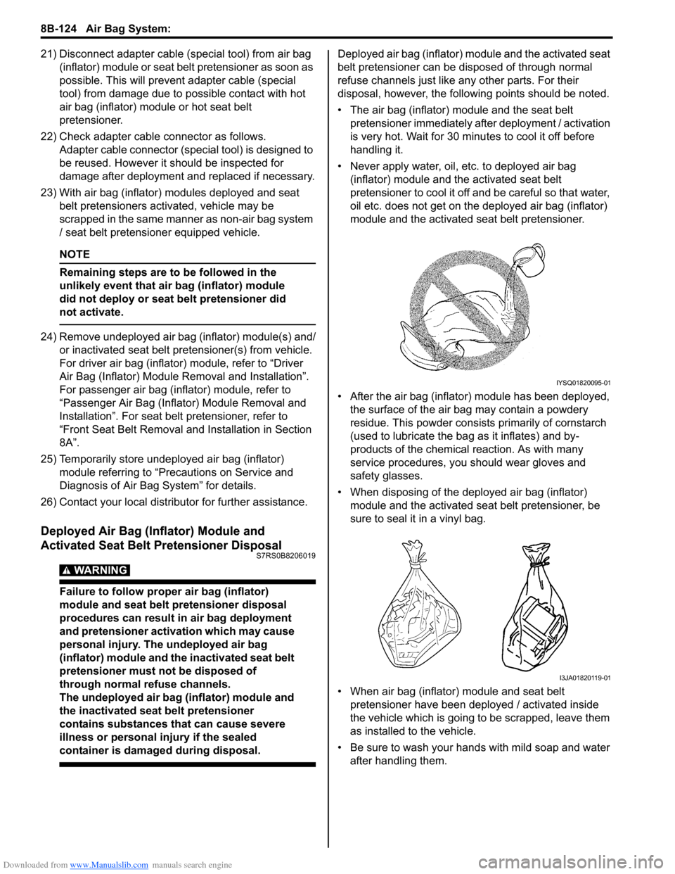
• Never apply water, oil, etc. to deployed air bag (inflator) module and the activated seat belt
pretensioner to cool it off and be careful so that water,
oil etc. does not get on the deployed air bag (inflator)
module and the activated seat belt pretensioner.
• After the air bag (inflator) module has been deployed, the surface of the air bag may contain a powdery
residue. This powder consists primarily of cornstarch
(used to lubricate the bag as it inflates) and by-
products of the chemical reaction. As with many
service procedures, you should wear gloves and
safety glasses.
• When disposing of the deployed air bag (inflator) module and the activated seat belt pretensioner, be
sure to seal it in a vinyl bag.
• When air bag (inflator) module and seat belt pretensioner have been deployed / activated inside
the vehicle which is going to be scrapped, leave them
as installed to the vehicle.
• Be sure to wash your hand s with mild soap and water
after handling them.
IYSQ01820095-01
I3JA01820119-01
Page 1288 of 1496
Downloaded from www.Manualslib.com manuals search engine 9B-6 Lighting Systems:
Headlight Bulb ReplacementS7RS0B9206002
WARNING!
• To avoid danger of being burned, don’t touch when the bulb is hot.
• Don’t touch glass surface of bulb, to avoid deteriorate as the case may be unclear
when bulb light on at dirty condition.
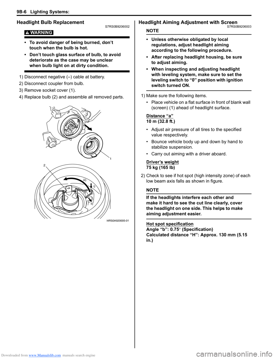
1) Disconnect negative (–) cable at battery.
2) Disconnect coupler from bulb.
3) Remove socket cover (1).
4) Replace bulb (2) and assemble all removed parts.
Headlight Aiming Adjustment with ScreenS7RS0B9206003
NOTE
• Unless otherwise obligated by local regulations, adjust headlight aiming
according to the following procedure.
• After replacing headlight housing, be sure to adjust aiming.
• When inspecting and adjusting headlight with leveling system, make sure to set the
leveling switch to “0 ” position with ignition
switch turned ON.
1) Make sure the following items.
• Place vehicle on a flat surface in front of blank wall (screen) (1) ahead of headlight surface.
Distance “a”
10 m (32.8 ft.)
• Adjust air pressure of all tires to the specified value respectively.
• Bounce vehicle body up and down by hand to stabilize suspension.
• Carry out aiming with a driver aboard.
Driver’s weight
75 kg (165 lb)
2) Check to see if hot spot (high intensity zone) of each low beam axis falls as shown in figure.
NOTE
If the headlights interfere each other and
make it hard to see the cut line clearly, cover
the headlight on one side. This helps to make
aiming adjustment easier.
Hot spot specification
Angle “b”: 0.75 ° (Specification)
Calculated distance “H”: Approx. 130 mm (5.15
in.)
1
iii)
2
i)
ii)
I4RS0A920005-01
Page 1294 of 1496
Downloaded from www.Manualslib.com manuals search engine 9B-12 Lighting Systems:
Front Fog Light Aiming Adjustment with Screen
(If Equipped)
S7RS0B9206018
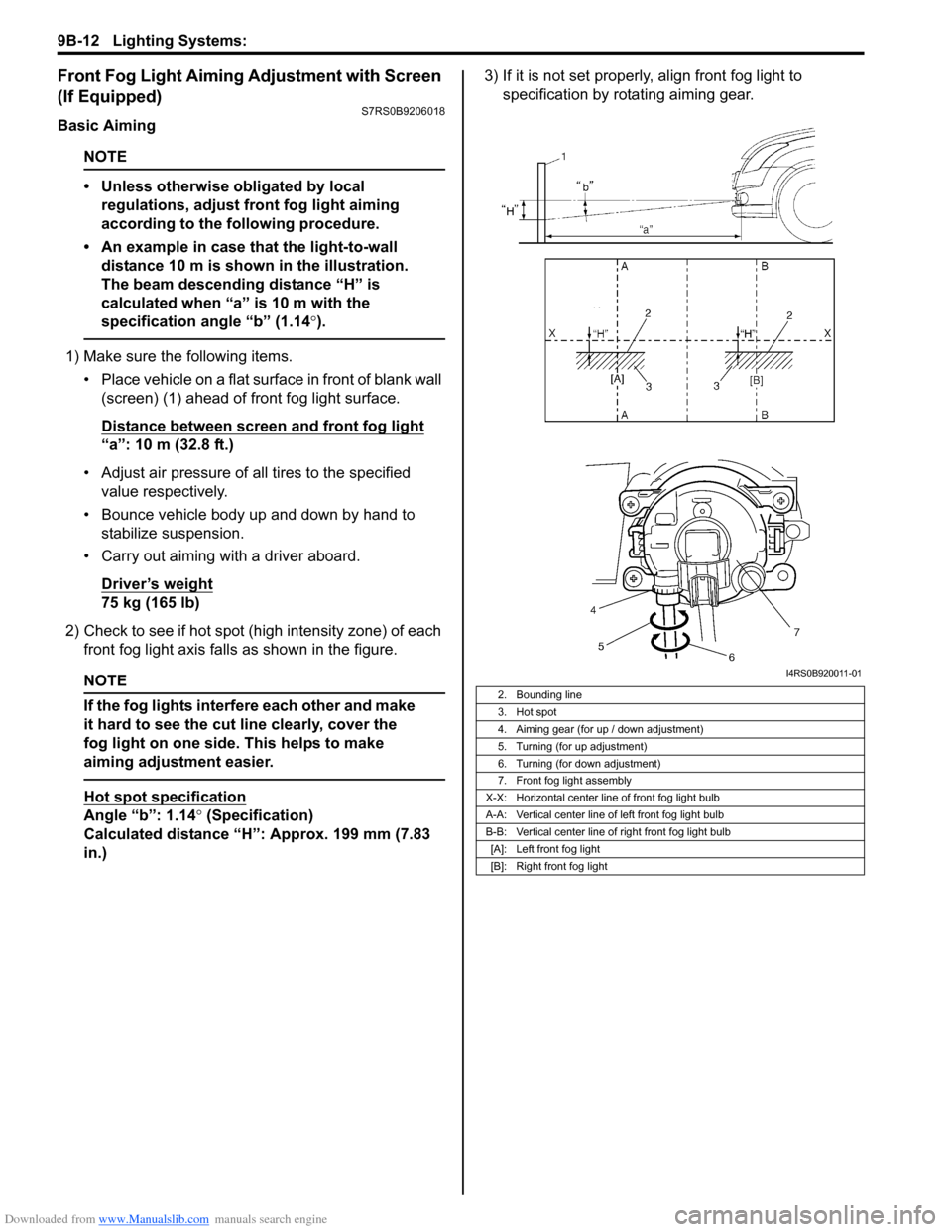
Basic Aiming
NOTE
• Unless otherwise obligated by local regulations, adjust front fog light aiming
according to the following procedure.
• An example in case that the light-to-wall distance 10 m is shown in the illustration.
The beam descending distance “H” is
calculated when “a” is 10 m with the
specification angle “b” (1.14 °).
1) Make sure the following items.
• Place vehicle on a flat surface in front of blank wall (screen) (1) ahead of front fog light surface.
Distance between screen and front fog light
“a”: 10 m (32.8 ft.)
• Adjust air pressure of all tires to the specified value respectively.
• Bounce vehicle body up and down by hand to stabilize suspension.
• Carry out aiming with a driver aboard.
Driver’s weight
75 kg (165 lb)
2) Check to see if hot spot (h igh intensity zone) of each
front fog light axis falls as shown in the figure.
NOTE
If the fog lights interfere each other and make
it hard to see the cut line clearly, cover the
fog light on one side. This helps to make
aiming adjustment easier.
Hot spot specification
Angle “b”: 1.14° (Specification)
Calculated distance “H”: Approx. 199 mm (7.83
in.) 3) If it is not set properly
, align front fog light to
specification by rotating aiming gear.
2. Bounding line
3. Hot spot
4. Aiming gear (for up / down adjustment)
5. Turning (for up adjustment)
6. Turning (for down adjustment)
7. Front fog light assembly
X-X: Horizontal center line of front fog light bulb
A-A: Vertical center line of left front fog light bulb
B-B: Vertical center line of right front fog light bulb [A]: Left front fog light
[B]: Right front fog light
I4RS0B920011-01
Page 1308 of 1496
Downloaded from www.Manualslib.com manuals search engine 9C-13 Instrumentation / Driver Info. / Horn:
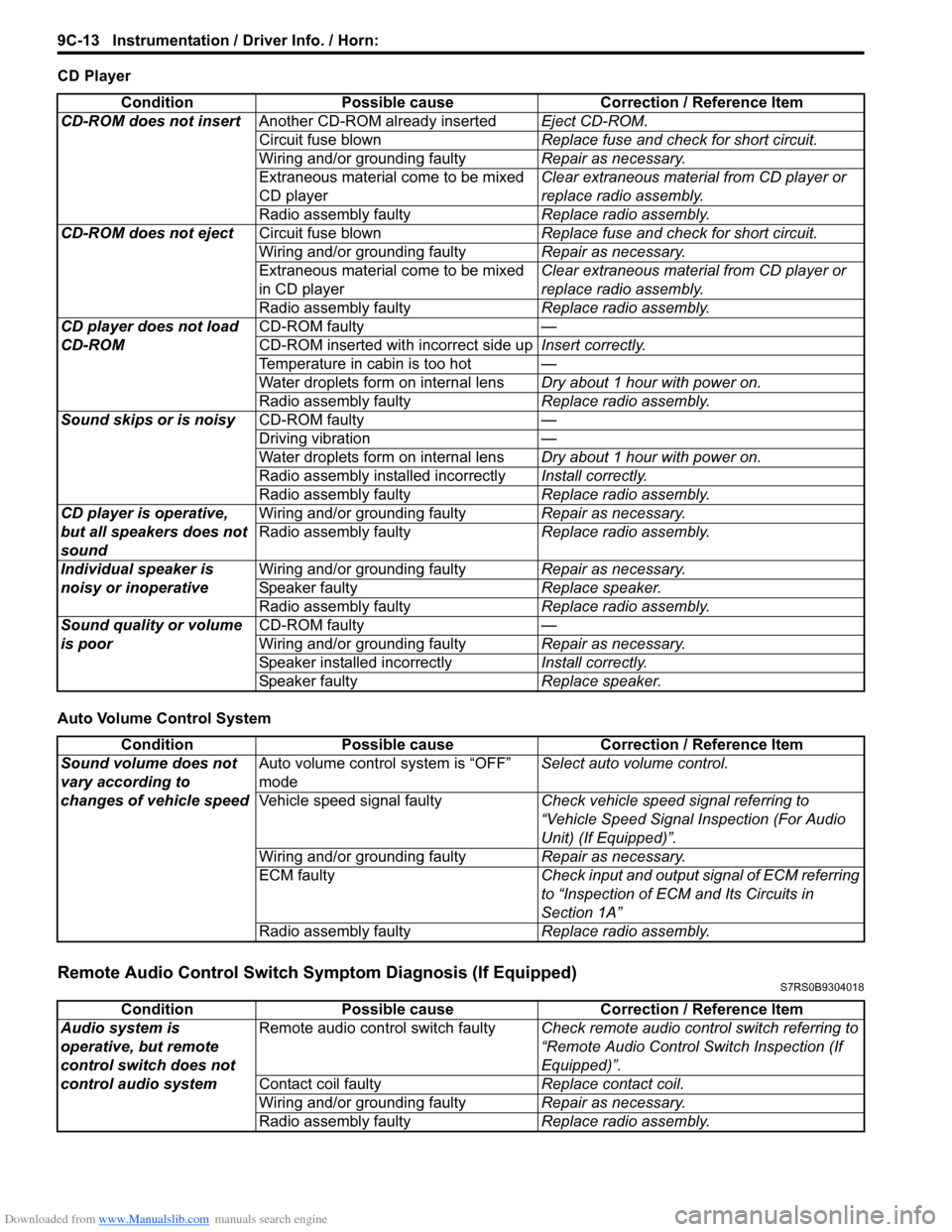
CD Player
Auto Volume Control System
Remote Audio Control Switch Symptom Diagnosis (If Equipped)S7RS0B9304018
ConditionPossible cause Correction / Reference Item
CD-ROM does not insert Another CD-ROM already inserted Eject CD-ROM.
Circuit fuse blown Replace fuse and check for short circuit.
Wiring and/or grounding faulty Repair as necessary.
Extraneous material come to be mixed
CD player Clear extraneous material from CD player or
replace radio assembly.
Radio assembly faulty Replace radio assembly.
CD-ROM does not eject Circuit fuse blown Replace fuse and check for short circuit.
Wiring and/or grounding faulty Repair as necessary.
Extraneous material come to be mixed
in CD player Clear extraneous material from CD player or
replace radio assembly.
Radio assembly faulty Replace radio assembly.
CD player does not load
CD-ROM CD-ROM faulty
—
CD-ROM inserted wit h incorrect side upInsert correctly.
Temperature in cabin is too hot —
Water droplets form on internal lens Dry about 1 hour with power on.
Radio assembly faulty Replace radio assembly.
Sound skips or is noisy CD-ROM faulty —
Driving vibration —
Water droplets form on internal lens Dry about 1 hour with power on.
Radio assembly installed incorrectly Install correctly.
Radio assembly faulty Replace radio assembly.
CD player is operative,
but all speakers does not
sound Wiring and/or grounding faulty
Repair as necessary.
Radio assembly faulty Replace radio assembly.
Individual speaker is
noisy or inoperative Wiring and/or grounding faulty
Repair as necessary.
Speaker faulty Replace speaker.
Radio assembly faulty Replace radio assembly.
Sound quality or volume
is poor CD-ROM faulty
—
Wiring and/or grounding faulty Repair as necessary.
Speaker installed incorrectly Install correctly.
Speaker faulty Replace speaker.
ConditionPossible cause Correction / Reference Item
Sound volume does not
vary according to
changes of vehicle speed Auto volume control system is “OFF”
mode
Select auto volume control.
Vehicle speed signal faulty Check vehicle speed signal referring to
“Vehicle Speed Signal Inspection (For Audio
Unit) (If Equipped)”.
Wiring and/or grounding faulty Repair as necessary.
ECM faulty Check input and output signal of ECM referring
to “Inspection of ECM and Its Circuits in
Section 1A”
Radio assembly faulty Replace radio assembly.
ConditionPossible cause Correction / Reference Item
Audio system is
operative, but remote
control switch does not
control audio system Remote audio control switch faulty
Check remote audio control switch referring to
“Remote Audio Control Switch Inspection (If
Equipped)”.
Contact coil faulty Replace contact coil.
Wiring and/or grounding faulty Repair as necessary.
Radio assembly faulty Replace radio assembly.