Engine Cooling System SUZUKI SX4 2006 1.G Service Owner's Manual
[x] Cancel search | Manufacturer: SUZUKI, Model Year: 2006, Model line: SX4, Model: SUZUKI SX4 2006 1.GPages: 1556, PDF Size: 37.31 MB
Page 255 of 1556
Downloaded from www.Manualslib.com manuals search engine Engine General Information and Diagnosis: 1A-205
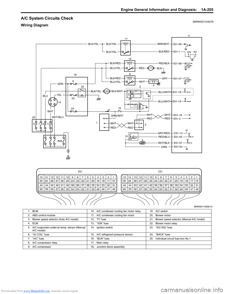
A/C System Circuits CheckS6RW0D1104078
Wiring Diagram
BLU/WHT
BLU/WHTE01-19
E01-19
21
E01C01
3 4
18 19 5 6 7 10 11
17 20
47 46 49 50 51 21 22
5216 259
24 14
29
55 57 54 53 59
60 582
26 27 28 15
30
56 4832 31 34 35 36 37 40 42 39 38 44
45 43 41 331 12 13
238 3 4
18 19 5 6 7 10 11
17 20
47 46 49 50 51 21 22
5216 259
24 14
29
55 57 54 53 59
60 582
26 27 28 15
30
56 4832 31 34 35 36 37 40 42 39 38 44
45 43 41 331 12 13
238
BLK/RED
BRN/WHT
12V5V
17
10
8
E01-1
E01-60
BLK/YEL
REDBLK11
WHT9
34
RED/BLK
BLK/REDE01-47
E01-58
BLU/YELGRY
19
2 1
20
5 15
WHT
RED
WHT
RED
WHT
RED
WHT
RED
E01-18E01-3
WHT/BLK
C01-14
E01-57
E01-54
E01-55RED/BLU
ORN
GRY/RED
BLK/YEL
GRN/WHT
BLK/WHT
WHT
1423
24
6
22 18
80A
1316 7 12
GRN
25
BLK/RED
BLU/YEL
YEL
WHT/BLU
BLK/YELBLK/YEL
BLU
I6RW0D110056-01
1. BCM 10. A/C condenser cooling fan motor relay 19. A/C switch
2. ABS control module 11. A/C condenser cooling fan motor 20. Blower motor
3. Blower speed selector (Auto A/C model) 12. “FI” fuse 21. Blower speed selector (Manual A/C model)
4. ECM 13. “IGN” fuse 22. Blower motor relay
5. A/C evaporator outlet air temp. sensor (Manual
A/C model)14. Ignition switch 23. “IG2 SIG” fuse
6. “IG COIL” fuse 15. A/C refrigerant pressure sensor 24. “BACK” fuse
7. “A/C” fuse 16. “BLW” fuse 25. Individual circuit fuse box No.1
8. A/C compressor relay 17. Main relay
9. A/C compressor 18. Junction block assembly
Page 256 of 1556
Downloaded from www.Manualslib.com manuals search engine 1A-206 Engine General Information and Diagnosis:
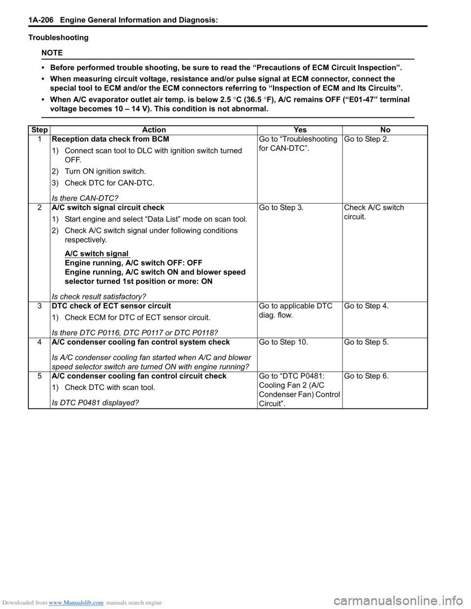
Troubleshooting
NOTE
• Before performed trouble shooting, be sure to read the “Precautions of ECM Circuit Inspection”.
• When measuring circuit voltage, resistance and/or pulse signal at ECM connector, connect the
special tool to ECM and/or the ECM connectors referring to “Inspection of ECM and Its Circuits”.
• When A/C evaporator outlet air temp. is below 2.5 °C (36.5 °F), A/C remains OFF (“E01-47” terminal
voltage becomes 10 – 14 V). This condition is not abnormal.
Step Action Yes No
1Reception data check from BCM
1) Connect scan tool to DLC with ignition switch turned
OFF.
2) Turn ON ignition switch.
3) Check DTC for CAN-DTC.
Is there CAN-DTC?Go to “Troubleshooting
for CAN-DTC”.Go to Step 2.
2A/C switch signal circuit check
1) Start engine and select “Data List” mode on scan tool.
2) Check A/C switch signal under following conditions
respectively.
A/C switch signal
Engine running, A/C switch OFF: OFF
Engine running, A/C switch ON and blower speed
selector turned 1st position or more: ON
Is check result satisfactory?Go to Step 3. Check A/C switch
circuit.
3DTC check of ECT sensor circuit
1) Check ECM for DTC of ECT sensor circuit.
Is there DTC P0116, DTC P0117 or DTC P0118?Go to applicable DTC
diag. flow.Go to Step 4.
4A/C condenser cooling fan control system check
Is A/C condenser cooling fan started when A/C and blower
speed selector switch are turned ON with engine running?Go to Step 10. Go to Step 5.
5A/C condenser cooling fan control circuit check
1) Check DTC with scan tool.
Is DTC P0481 displayed?Go to “DTC P0481:
Cooling Fan 2 (A/C
Condenser Fan) Control
Circuit”.Go to Step 6.
Page 257 of 1556

Downloaded from www.Manualslib.com manuals search engine Engine General Information and Diagnosis: 1A-207
6A/C evaporator outlet air temp. sensor check
1) Disconnect connectors from ECM with ignition switch
turned OFF.
2) Check for proper connection to “E01-57” and “E01-54”
wire terminals of ECM connector.
3) If OK, measure resistance between “E01-57” and “E01-
54” wire terminals of ECM connector.
Evaporator temp. sensor resistance
At 0 °C: 6.3 – 6.9 kΩ
At 25 °C: 1.8 – 2.2 kΩ
Is resistance within specification?Go to Step 7. Faulty A/C evaporator
outlet air temp. sensor
or its circuit.
7DTC check of A/C refrigerant pressure sensor circuit
1) Connect scan tool to DLC with ignition switch turned
OFF.
2) Turn ON ignition switch.
3) Check ECM for DTC of A/C refrigerant pressure sensor
circuit.
Is there DTC P0532 or DTC P0533?Go to applicable DTC
diag. flow.Go to Step 8.
8A/C refrigerant pressure sensor voltage check
1) Check A/C refrigerant pressure sensor voltage referring
to “Inspection of ECM and Its Circuits”.
Is voltage within specified value?Go to Step 9. Check amount of
refrigerant. If OK,
replace A/C refrigerant
pressure sensor.
9A/C condenser cooling fan check
1) Check A/C condenser cooling fan referring to
“Condenser Cooling Fan Inspection in Section 7B”.
Is check result satisfactory?A/C condenser cooling
fan drive circuit
malfunction. If circuit is
OK, go to Step 6.Replace A/C condenser
cooling fan motor.
10A/C compressor control system check
Is A/C compressor started when A/C and blower speed
selector switch are turned ON with engine running?A/C system is in good
condition.Go to Step 11. Step Action Yes No
7
6
5
4
3
2
1
10
20
30
4050 010
2030
60 70
80 ResistanceTemperatureI3RB0A110053-01
Page 261 of 1556
Downloaded from www.Manualslib.com manuals search engine Engine General Information and Diagnosis: 1A-211
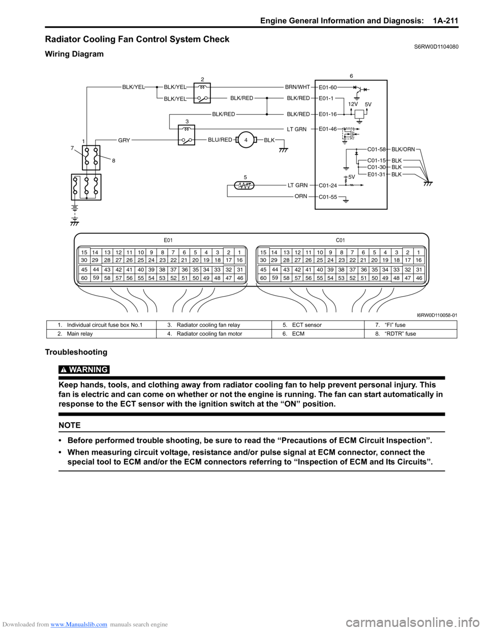
Radiator Cooling Fan Control System CheckS6RW0D1104080
Wiring Diagram
Troubleshooting
WARNING!
Keep hands, tools, and clothing away from radiator cooling fan to help prevent personal injury. This
fan is electric and can come on whether or not the engine is running. The fan can start automatically in
response to the ECT sensor with the ignition switch at the “ON” position.
NOTE
• Before performed trouble shooting, be sure to read the “Precautions of ECM Circuit Inspection”.
• When measuring circuit voltage, resistance and/or pulse signal at ECM connector, connect the
special tool to ECM and/or the ECM connectors referring to “Inspection of ECM and Its Circuits”.
E01C01
3 4
18 19 5 6 7 10 11
17 20
47 46 49 50 51 21 22
5216 259
24 14
29
55 57 54 53 59
60 582
26 27 28 15
30
56 4832 31 34 35 36 37 40 42 39 38 44
45 43 41 331 12 13
238 3 4
18 19 5 6 7 10 11
17 20
47 46 49 50 51 21 22
5216 259
24 14
29
55 57 54 53 59
60 582
26 27 28 15
30
56 4832 31 34 35 36 37 40 42 39 38 44
45 43 41 331 12 13
238
BLK/REDBLK/RED
BLK/YELBLK/YEL
BLK/YEL
BRN/WHT
12V
5V5V
26
E01-1
E01-60
C01-58
C01-15 C01-30
BLK/ORN
BLKBLK
BLK/RED
LT GRN
BLK/REDE01-16
E01-46
BLU/REDBLKGRY
LT GRN
ORN
C01-24
C01-55 3
4
5
E01-31 BLK
8 71
I6RW0D110058-01
1. Individual circuit fuse box No.1 3. Radiator cooling fan relay 5. ECT sensor 7. “FI” fuse
2. Main relay 4. Radiator cooling fan motor 6. ECM 8. “RDTR” fuse
Page 262 of 1556
Downloaded from www.Manualslib.com manuals search engine 1A-212 Engine General Information and Diagnosis:
Repair Instructions
Idle Speed and IAC Throttle Valve Opening
Inspection
S6RW0D1106001
Before idle speed check, make sure of the following.
• Lead wires and hoses of electronic fuel injection and
engine and emission control systems are connected
securely.
• Valve lash is checked according to maintenance
schedule.
• Ignition timing is within specification.
• All accessories (wipers, heater, lights, A/C, etc.) are
out of service.
• Air cleaner has been properly installed and is in good
condition.
• No abnormal air drawn in from air intake system.After all items are confirmed, check idle speed and IAC
throttle opening as follows.NOTE
Before starting engine, place transmission
gear shift lever in “Neutral”, and set parking
brake and block drive wheels.
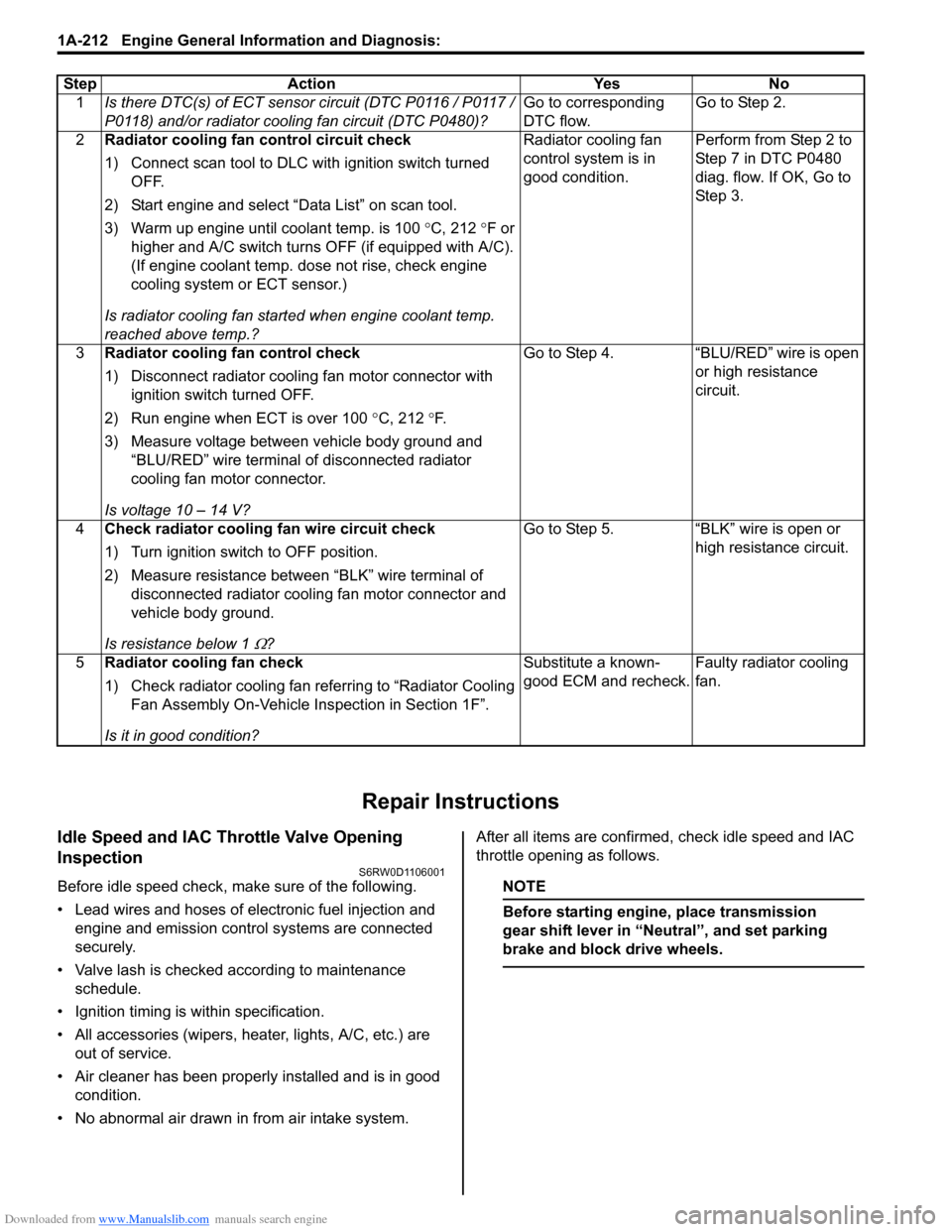
Step Action Yes No
1Is there DTC(s) of ECT sensor circuit (DTC P0116 / P0117 /
P0118) and/or radiator cooling fan circuit (DTC P0480)?Go to corresponding
DTC flow.Go to Step 2.
2Radiator cooling fan control circuit check
1) Connect scan tool to DLC with ignition switch turned
OFF.
2) Start engine and select “Data List” on scan tool.
3) Warm up engine until coolant temp. is 100 °C, 212 °F or
higher and A/C switch turns OFF (if equipped with A/C).
(If engine coolant temp. dose not rise, check engine
cooling system or ECT sensor.)
Is radiator cooling fan started when engine coolant temp.
reached above temp.?Radiator cooling fan
control system is in
good condition.Perform from Step 2 to
Step 7 in DTC P0480
diag. flow. If OK, Go to
Ste p 3.
3Radiator cooling fan control check
1) Disconnect radiator cooling fan motor connector with
ignition switch turned OFF.
2) Run engine when ECT is over 100 °C, 212 °F.
3) Measure voltage between vehicle body ground and
“BLU/RED” wire terminal of disconnected radiator
cooling fan motor connector.
Is voltage 10 – 14 V?Go to Step 4. “BLU/RED” wire is open
or high resistance
circuit.
4Check radiator cooling fan wire circuit check
1) Turn ignition switch to OFF position.
2) Measure resistance between “BLK” wire terminal of
disconnected radiator cooling fan motor connector and
vehicle body ground.
Is resistance below 1
Ω?Go to Step 5. “BLK” wire is open or
high resistance circuit.
5Radiator cooling fan check
1) Check radiator cooling fan referring to “Radiator Cooling
Fan Assembly On-Vehicle Inspection in Section 1F”.
Is it in good condition?Substitute a known-
good ECM and recheck.Faulty radiator cooling
fan.
Page 275 of 1556
Downloaded from www.Manualslib.com manuals search engine Engine Electrical Devices: 1C-7
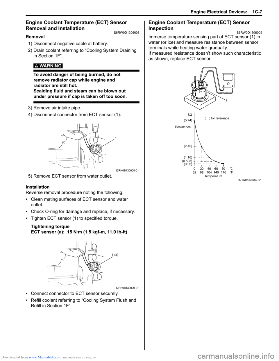
Engine Coolant Temperature (ECT) Sensor
Removal and Installation
S6RW0D1306008
Removal
1) Disconnect negative cable at battery.
2) Drain coolant referring to “Cooling System Draining
in Section 1F”.
WARNING!
To avoid danger of being burned, do not
remove radiator cap while engine and
radiator are still hot.
Scalding fluid and steam can be blown out
under pressure if cap is taken off too soon.
3) Remove air intake pipe.
4) Disconnect connector from ECT sensor (1).
5) Remove ECT sensor from water outlet.
Installation
Reverse removal procedure noting the following.
• Clean mating surfaces of ECT sensor and water
outlet.
• Check O-ring for damage and replace, if necessary.
• Tighten ECT sensor (1) to specified torque.
Tightening torque
ECT sensor (a): 15 N·m (1.5 kgf-m, 11.0 lb-ft)
• Connect connector to ECT sensor securely.
• Refill coolant referring to “Cooling System Flush and
Refill in Section 1F”.
Engine Coolant Temperature (ECT) Sensor
Inspection
S6RW0D1306009
Immerse temperature sensing part of ECT sensor (1) in
water (or ice) and measure resistance between sensor
terminals while heating water gradually.
If measured resistance doesn’t show such characteristic
as shown, replace ECT sensor.
1
I2RH0B130008-01
1,(a)
I2RH0B130009-01
I5RW0A130007-01
Page 296 of 1556
Downloaded from www.Manualslib.com manuals search engine 1D-14 Engine Mechanical:
Throttle Body On-Vehicle InspectionS6RW0D1406006
Check electric throttle body assembly referring to
“Throttle Valve Operation Check” and “Electric Throttle
Body Assembly Operation Check” under “Electric
Throttle Body Assembly On-Vehicle Inspection in
Section 1C”.
Electric Throttle Body Assembly Removal and
Installation
S6RW0D1406047
CAUTION!
Never disassemble electric throttle body.
Disassembly will spoil its original
performance. If faulty condition is found,
replace it with new one.
Removal
1) Disconnect negative cable at battery.
2) Drain coolant referring to “Cooling System Draining
in Section 1F”.
3) Remove air cleaner assembly referring to “Air
Cleaner Assembly Removal and Installation”.
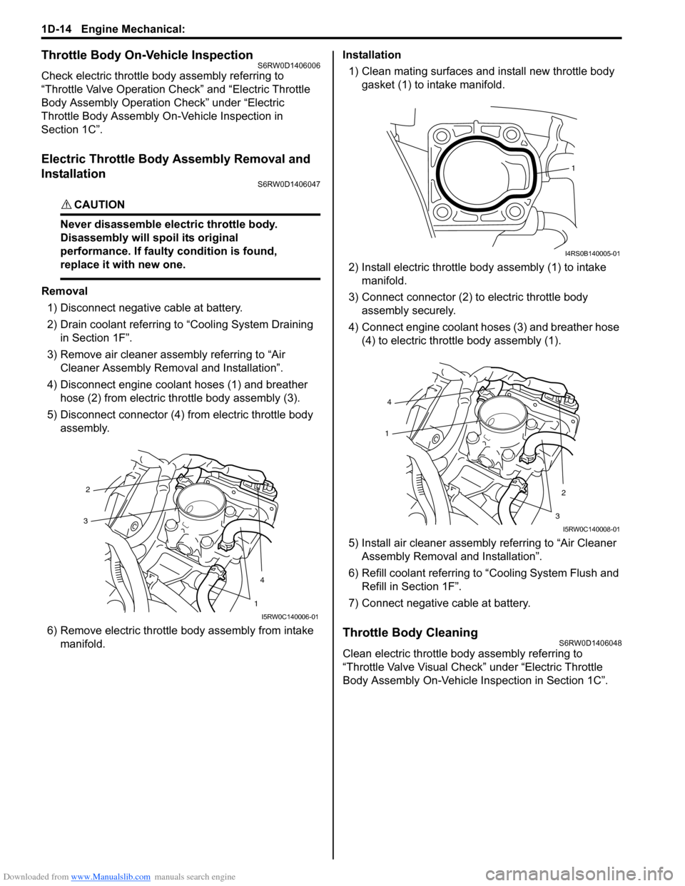
4) Disconnect engine coolant hoses (1) and breather
hose (2) from electric throttle body assembly (3).
5) Disconnect connector (4) from electric throttle body
assembly.
6) Remove electric throttle body assembly from intake
manifold.Installation
1) Clean mating surfaces and install new throttle body
gasket (1) to intake manifold.
2) Install electric throttle body assembly (1) to intake
manifold.
3) Connect connector (2) to electric throttle body
assembly securely.
4) Connect engine coolant hoses (3) and breather hose
(4) to electric throttle body assembly (1).
5) Install air cleaner assembly referring to “Air Cleaner
Assembly Removal and Installation”.
6) Refill coolant referring to “Cooling System Flush and
Refill in Section 1F”.
7) Connect negative cable at battery.
Throttle Body CleaningS6RW0D1406048
Clean electric throttle body assembly referring to
“Throttle Valve Visual Check” under “Electric Throttle
Body Assembly On-Vehicle Inspection in Section 1C”.
2
4
3
1
I5RW0C140006-01
1
I4RS0B140005-01
4
2
1
3
I5RW0C140008-01
Page 297 of 1556
Downloaded from www.Manualslib.com manuals search engine Engine Mechanical: 1D-15
Intake Manifold Removal and InstallationS6RW0D1406011
Removal
1) Remove throttle body referring to “Electric Throttle
Body Assembly Removal and Installation”.
2) Disconnect MAP sensor connector (1).
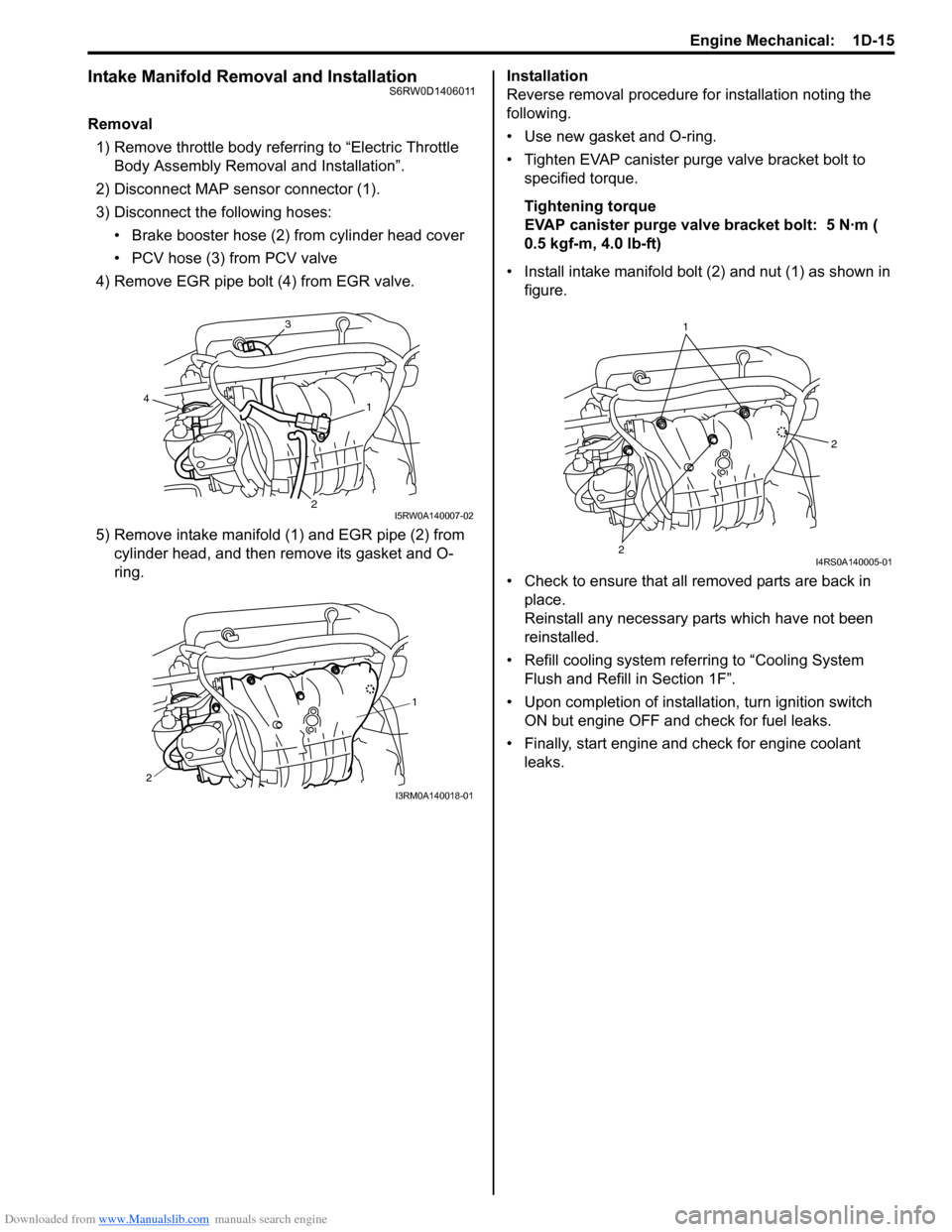
3) Disconnect the following hoses:
• Brake booster hose (2) from cylinder head cover
• PCV hose (3) from PCV valve
4) Remove EGR pipe bolt (4) from EGR valve.
5) Remove intake manifold (1) and EGR pipe (2) from
cylinder head, and then remove its gasket and O-
ring.Installation
Reverse removal procedure for installation noting the
following.
• Use new gasket and O-ring.
• Tighten EVAP canister purge valve bracket bolt to
specified torque.
Tightening torque
EVAP canister purge valve bracket bolt: 5 N·m (
0.5 kgf-m, 4.0 lb-ft)
• Install intake manifold bolt (2) and nut (1) as shown in
figure.
• Check to ensure that all removed parts are back in
place.
Reinstall any necessary parts which have not been
reinstalled.
• Refill cooling system referring to “Cooling System
Flush and Refill in Section 1F”.
• Upon completion of installation, turn ignition switch
ON but engine OFF and check for fuel leaks.
• Finally, start engine and check for engine coolant
leaks.
3
1
24
I5RW0A140007-02
1
2
I3RM0A140018-01
1
2
2
I4RS0A140005-01
Page 299 of 1556
Downloaded from www.Manualslib.com manuals search engine Engine Mechanical: 1D-17
Engine Assembly Removal and InstallationS6RW0D1406013
Removal
1) Relieve fuel pressure according to “Fuel Pressure
Relief Procedure in Section 1G”.
2) Disconnect negative and positive cable at battery.
3) Disconnect ECM connectors.
4) Remove battery and battery tray with ECM.
5) Remove right and left side engine under covers.
6) Remove A/C compressor belt by referring to
“Compressor Drive Belt Removal and Installation in
Section 7B” or “Compressor Drive Belt Removal and
Installation in Section 7B”.
7) Drain engine oil referring to “Engine Oil and Filter
Change in Section 0B”.
8) Drain transaxle oil referring to “Manual Transaxle Oil
Change in Section 5B” or “A/T Fluid Change in
Section 5A”.
9) Drain transfer oil referring to “Transfer Oil Change in
Section 3C”.
10) Drain coolant referring to “Cooling System Draining
in Section 1F”
11) Remove air cleaner assembly referring to “Air
Cleaner Assembly Removal and Installation”.
12) With hose connected, detach A/C compressor from
its bracket referring to “Compressor Assembly
Removal and Installation in Section 7B” or
“Compressor Assembly Removal and Installation in
Section 7B”.
CAUTION!
Suspend removed A/C compressor at a place
where no damage will be caused during
removal and installation of engine assembly.
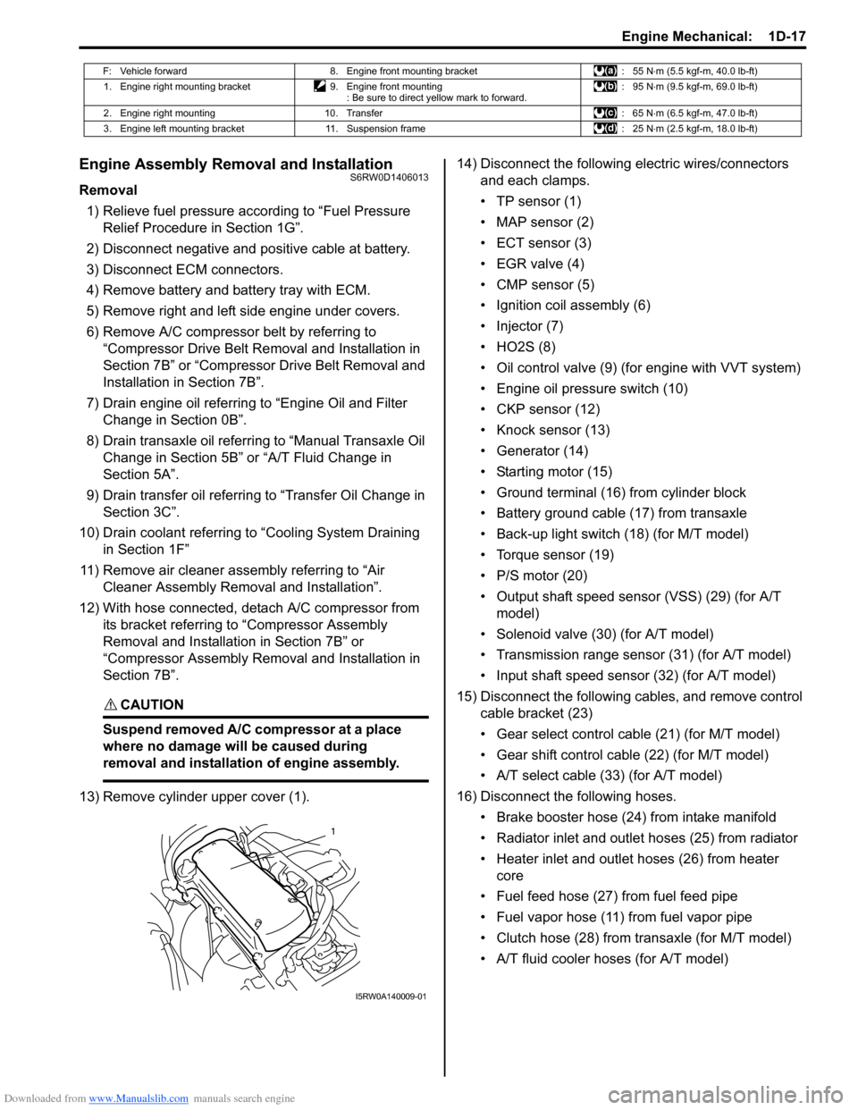
13) Remove cylinder upper cover (1).14) Disconnect the following electric wires/connectors
and each clamps.
• TP sensor (1)
• MAP sensor (2)
• ECT sensor (3)
•EGR valve (4)
• CMP sensor (5)
• Ignition coil assembly (6)
• Injector (7)
•HO2S (8)
• Oil control valve (9) (for engine with VVT system)
• Engine oil pressure switch (10)
• CKP sensor (12)
• Knock sensor (13)
• Generator (14)
• Starting motor (15)
• Ground terminal (16) from cylinder block
• Battery ground cable (17) from transaxle
• Back-up light switch (18) (for M/T model)
• Torque sensor (19)
• P/S motor (20)
• Output shaft speed sensor (VSS) (29) (for A/T
model)
• Solenoid valve (30) (for A/T model)
• Transmission range sensor (31) (for A/T model)
• Input shaft speed sensor (32) (for A/T model)
15) Disconnect the following cables, and remove control
cable bracket (23)
• Gear select control cable (21) (for M/T model)
• Gear shift control cable (22) (for M/T model)
• A/T select cable (33) (for A/T model)
16) Disconnect the following hoses.
• Brake booster hose (24) from intake manifold
• Radiator inlet and outlet hoses (25) from radiator
• Heater inlet and outlet hoses (26) from heater
core
• Fuel feed hose (27) from fuel feed pipe
• Fuel vapor hose (11) from fuel vapor pipe
• Clutch hose (28) from transaxle (for M/T model)
• A/T fluid cooler hoses (for A/T model)
F: Vehicle forward 8. Engine front mounting bracket : 55 N⋅m (5.5 kgf-m, 40.0 lb-ft)
1. Engine right mounting bracket 9. Engine front mounting
: Be sure to direct yellow mark to forward.: 95 N⋅m (9.5 kgf-m, 69.0 lb-ft)
2. Engine right mounting 10. Transfer : 65 N⋅m (6.5 kgf-m, 47.0 lb-ft)
3. Engine left mounting bracket 11. Suspension frame : 25 N⋅m (2.5 kgf-m, 18.0 lb-ft)
1
I5RW0A140009-01
Page 303 of 1556
Downloaded from www.Manualslib.com manuals search engine Engine Mechanical: 1D-21
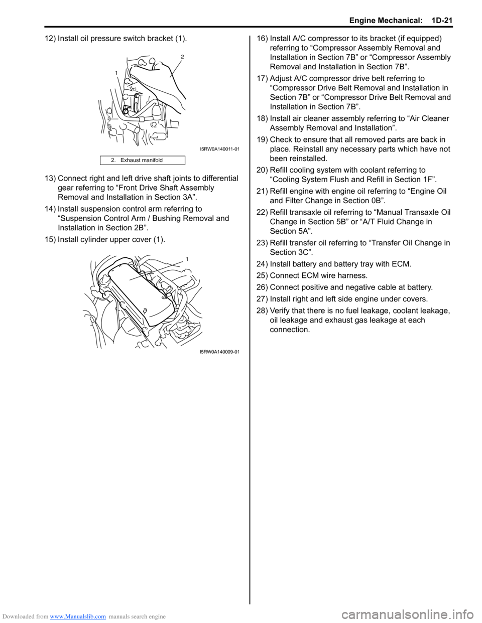
12) Install oil pressure switch bracket (1).
13) Connect right and left drive shaft joints to differential
gear referring to “Front Drive Shaft Assembly
Removal and Installation in Section 3A”.
14) Install suspension control arm referring to
“Suspension Control Arm / Bushing Removal and
Installation in Section 2B”.
15) Install cylinder upper cover (1).16) Install A/C compressor to its bracket (if equipped)
referring to “Compressor Assembly Removal and
Installation in Section 7B” or “Compressor Assembly
Removal and Installation in Section 7B”.
17) Adjust A/C compressor drive belt referring to
“Compressor Drive Belt Removal and Installation in
Section 7B” or “Compressor Drive Belt Removal and
Installation in Section 7B”.
18) Install air cleaner assembly referring to “Air Cleaner
Assembly Removal and Installation”.
19) Check to ensure that all removed parts are back in
place. Reinstall any necessary parts which have not
been reinstalled.
20) Refill cooling system with coolant referring to
“Cooling System Flush and Refill in Section 1F”.
21) Refill engine with engine oil referring to “Engine Oil
and Filter Change in Section 0B”.
22) Refill transaxle oil referring to “Manual Transaxle Oil
Change in Section 5B” or “A/T Fluid Change in
Section 5A”.
23) Refill transfer oil referring to “Transfer Oil Change in
Section 3C”.
24) Install battery and battery tray with ECM.
25) Connect ECM wire harness.
26) Connect positive and negative cable at battery.
27) Install right and left side engine under covers.
28) Verify that there is no fuel leakage, coolant leakage,
oil leakage and exhaust gas leakage at each
connection.
2. Exhaust manifold
1
2
I5RW0A140011-01
1
I5RW0A140009-01