key TOYOTA 4RUNNER 2013 N280 / 5.G Manual Online
[x] Cancel search | Manufacturer: TOYOTA, Model Year: 2013, Model line: 4RUNNER, Model: TOYOTA 4RUNNER 2013 N280 / 5.GPages: 704, PDF Size: 11.56 MB
Page 445 of 704
445
3-6. Using the
storage features
3
Interior features
4RUNNER_U
Glove box
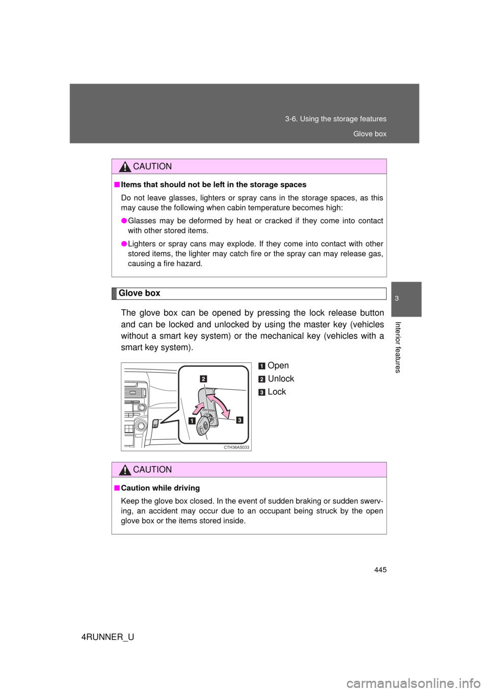
The glove box can be opened by pr essing the lock release button
and can be locked and unlocked by using the master key (vehicles
without a smart key system) or the mechanical key (vehicles with a
smart key system).
Open
Unlock
Lock
CAUTION
■Items that should not be left in the storage spaces
Do not leave glasses, lighters or spray cans in the storage spaces, as this
may cause the following when cabin temperature becomes high:
● Glasses may be deformed by heat or cracked if they come into contact
with other stored items.
● Lighters or spray cans may explode. If they come into contact with other
stored items, the lighter may catch fire or the spray can may release gas,
causing a fire hazard.
CTH36AS033
CAUTION
■Caution while driving
Keep the glove box closed. In the event of sudden braking or sudden swerv-
ing, an accident may occur due to an occupant being struck by the open
glove box or the items stored inside.
Glove box
Page 460 of 704
460 3-7. Other interior features
4RUNNER_U
■For quicker adjustment of the clock
To advance the minutes and hours quickly, press and hold the “M” or “H” but-
ton.
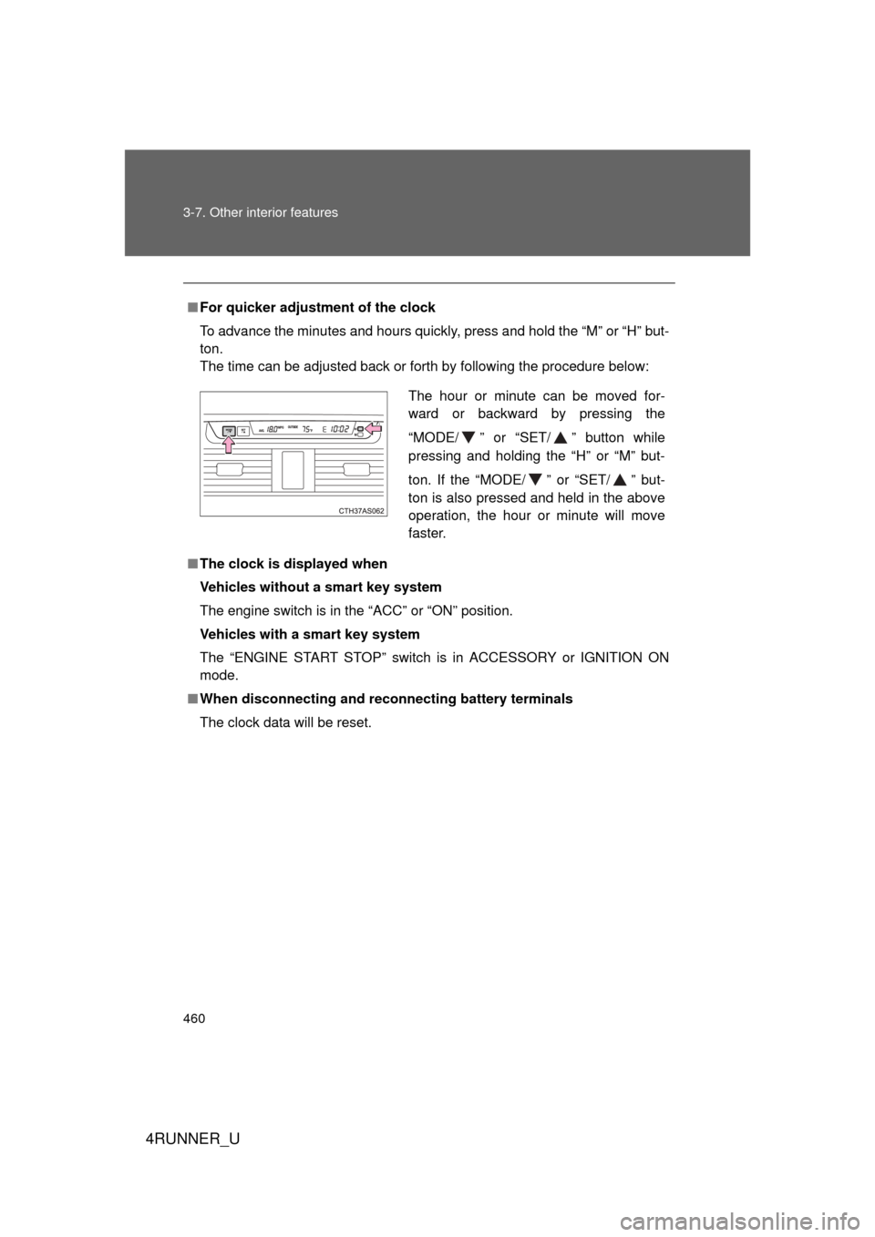
The time can be adjusted back or forth by following the procedure below:
■ The clock is displayed when
Vehicles without a smart key system
The engine switch is in the “ACC” or “ON” position.
Vehicles with a smart key system
The “ENGINE START STOP” switch is in ACCESSORY or IGNITION ON
mode.
■ When disconnecting and reco nnecting battery terminals
The clock data will be reset.
The hour or minute can be moved for-
ward or backward by pressing the
“MODE/ ” or “SET/ ” button while
pressing and holding the “H” or “M” but-
ton. If the “MODE/ ” or “SET/ ” but-
ton is also pressed and held in the above
operation, the hour or minute will move
faster.
Page 462 of 704
462 3-7. Other interior features
4RUNNER_U
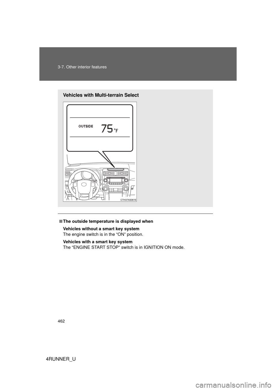
■The outside temperatur e is displayed when
Vehicles without a smart key system
The engine switch is in the “ON” position.
Vehicles with a smart key system
The “ENGINE START STOP” switch is in IGNITION ON mode.
Vehicles with Multi-terrain Select
Page 463 of 704
463
3-7. Other interior features
3
Interior features
4RUNNER_U
■
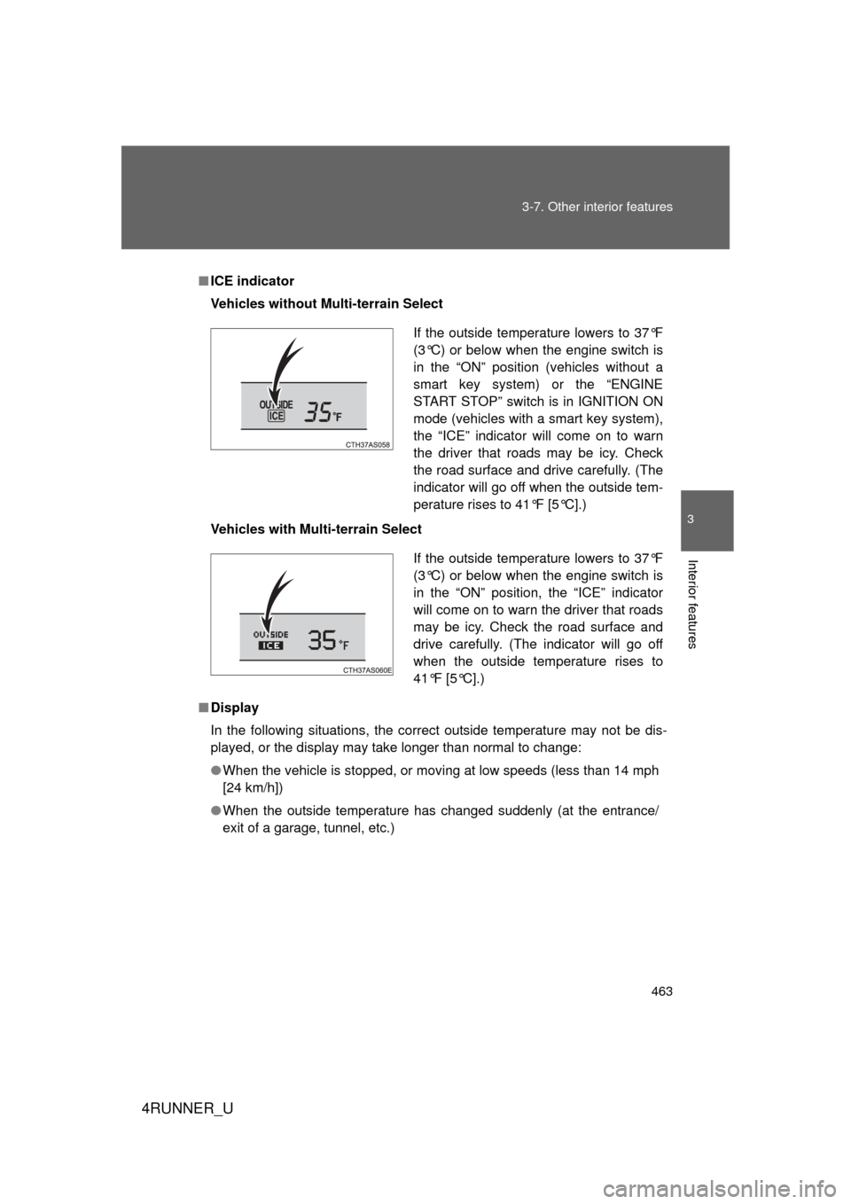
ICE indicator
Vehicles without Multi-terrain Select
Vehicles with Multi-terrain Select
■ Display
In the following situations, the correct outside temperature may not be dis-
played, or the display may take longer than normal to change:
● When the vehicle is stopped, or moving at low speeds (less than 14 mph
[24 km/h])
● When the outside temperature has changed suddenly (at the entrance/
exit of a garage, tunnel, etc.)
If the outside temperature lowers to 37°F
(3°C) or below when the engine switch is
in the “ON” position (vehicles without a
smart key system) or the “ENGINE
START STOP” switch is in IGNITION ON
mode (vehicles with a smart key system),
the “ICE” indicator will come on to warn
the driver that roads may be icy. Check
the road surface and drive carefully. (The
indicator will go off when the outside tem-
perature rises to 41°F [5°C].)
If the outside temperature lowers to 37°F
(3°C) or below when the engine switch is
in the “ON” position, the “ICE” indicator
will come on to warn the driver that roads
may be icy. Check the road surface and
drive carefully. (The indicator will go off
when the outside temperature rises to
41°F [5°C].)
Page 466 of 704
466 3-7. Other interior features
4RUNNER_U
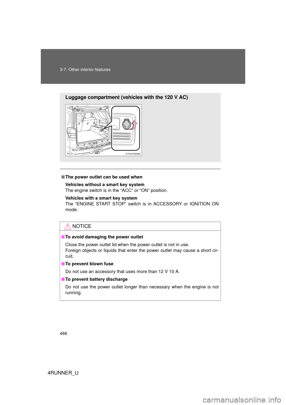
■The power outlet can be used when
Vehicles without a smart key system
The engine switch is in the “ACC” or “ON” position.
Vehicles with a smart key system
The “ENGINE START STOP” switch is in ACCESSORY or IGNITION ON
mode.
NOTICE
■ To avoid damaging the power outlet
Close the power outlet lid when the power outlet is not in use.
Foreign objects or liquids that enter the power outlet may cause a short cir-
cuit.
■ To prevent blown fuse
Do not use an accessory that uses more than 12 V 10 A.
■ To prevent battery discharge
Do not use the power outlet longer than necessary when the engine is not\
running.
Luggage compartment (vehicles with the 120 V AC)
CTH37AS086
Page 474 of 704
474
3-7. Other interior features
4RUNNER_U
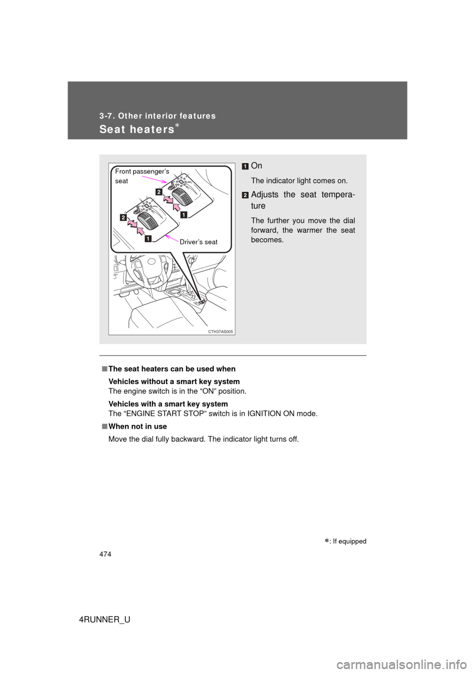
Seat heaters
■The seat heaters can be used when
Vehicles without a smart key system
The engine switch is in the “ON” position.
Vehicles with a smart key system
The “ENGINE START STOP” switch is in IGNITION ON mode.
■ When not in use
Move the dial fully backward. The indicator light turns off.
: If equipped
On
The indicator light comes on.
Adjusts the seat tempera-
ture
The further you move the dial
forward, the warmer the seat
becomes.
CTH37AS005
Front passenger’s
seat
Driver’s seat
Page 502 of 704

502 3-7. Other interior features
4RUNNER_U
Safety Connect LED light IndicatorsWhen the “ENGINE START STOP” switch is turned to IGNITION ON
mode (vehicles with a smart key system) or the engine switch is
turned to the “ON” position (vehicle s without a smart key system), the
red indicator light comes on for 2 seconds then turns off. Afterward,
the green indicator light comes on, indicating that the service is
active.
The following indicator light patter ns indicate specific system usage
conditions:
● Green indicator light on = Active service
● Green indicator light flashing = Safety Connect call in process
● Red indicator light (except at v ehicle start-up) = System malfunc-
tion (contact your Toyota dealer)
● No indicator light (off) = Safe ty Connect service not active
Safety Connect services
■ Automatic Collision Notification
In case of either airbag deployment or severe rear-end collision,
the system is design ed to automatically call the response center.
The responding agent receives th e vehicle’s location and attempts
to speak with the vehicle occup ants to assess the level of emer-
gency. If the occupants are unable to communicate, the agent
automatically treats the call as an emergency, contacts the nearest
emergency services provider to describe the situation, and
requests that assistance be sent to the location.
Page 507 of 704
Maintenance and care4
507
4RUNNER_U
4-1. Maintenance and careCleaning and protecting the vehicle exterior ......... 508
Cleaning and protecting the vehicle interior .......... 511
4-2. Maintenance Maintenance requirements .................. 514
General maintenance....... 517
Emission inspection and maintenance (I/M)
programs ........................ 521
4-3. Do-it-yourself maintenance Do-it-yourself service precautions .................... 522
Hood ................................ 525
Engine compartment ........ 526
Tires ................................. 542
Tire inflation pressure ...... 548
Wheels ............................. 552
Air conditioning filter......... 555
Wireless remote control/ electronic key battery ..... 557
Checking and replacing fuses .............................. 560
Light bulbs........................ 570
Page 515 of 704

515
4-2. Maintenance
4
Maintenance and care
4RUNNER_U
■
Reset the maintenance data (U.S.A. only)
After the required maintenance is performed according to the maintenance
schedule, please reset the maintenance data.
To reset the data, follow the procedures described below:
Switch the display to the trip meter A ( P. 188) when the engine is
running.
Vehicles without a smart key system
Turn the engine switch off.
Vehicles with a smart key system
Turn the “ENGINE START STOP” switch off.
Vehicles without a smart key system
While pressing the trip meter reset button ( P. 188), turn the
engine switch to the “ON” position (do not start the engine because
reset mode will be canceled). Continue to press and hold the button
until the trip meter displays “000000”.
Vehicles with a smart key system
While pressing the trip meter reset button ( P. 188), turn the
“ENGINE START STOP” switch to the IGNITION ON mode (do not
start the engine because otherwise the reset mode will be can-
celed). Continue to press and hold the button until the trip meter
displays “000000”.
■ Allow inspection and repairs to be performed by a Toyota dealer
● Toyota technicians are well-trained specialists and are kept up to date
with the latest service information. They are well informed about the
operations of all systems on your vehicle.
● Keep a copy of the repair order. It proves that the maintenance that has
been performed is under warranty coverage. If any problem should arise
while your vehicle is under warranty, your Toyota dealer will promptly
take care of it.
STEP 1
STEP 2
STEP 3
Page 533 of 704
533
4-3. Do-it-yourself maintenance
4
Maintenance and care
4RUNNER_U
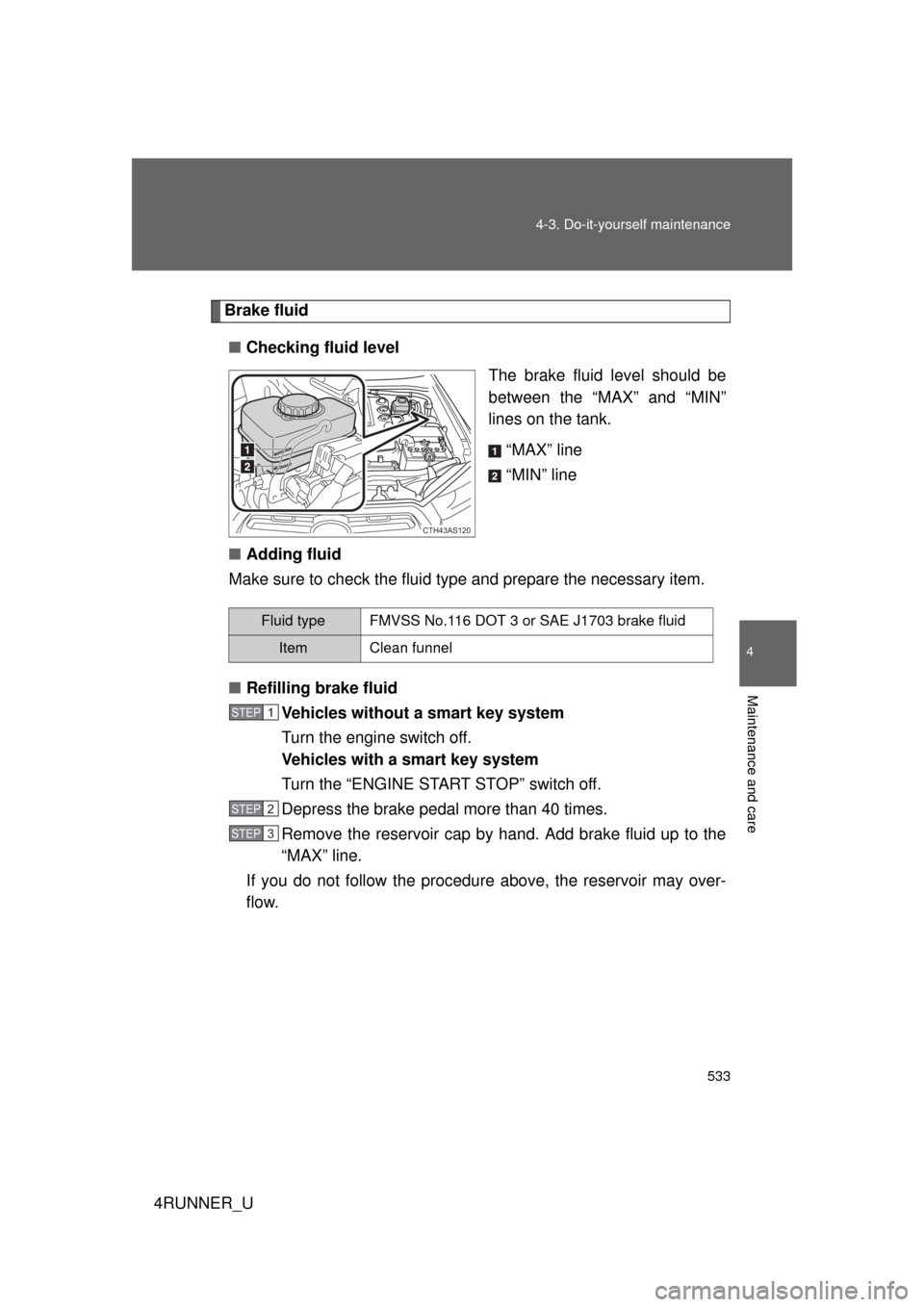
Brake fluid
■ Checking fluid level
The brake fluid level should be
between the “MAX” and “MIN”
lines on the tank.
“MAX” line
“MIN” line
■ Adding fluid
Make sure to check the fluid type and prepare the necessary item.
■ Refilling brake fluid
Vehicles without a smart key system
Turn the engine switch off.
Vehicles with a smart key system
Turn the “ENGINE START STOP” switch off.
Depress the brake pedal more than 40 times.
Remove the reservoir cap by hand. Add brake fluid up to the
“MAX” line.
If you do not follow the procedure above, the reservoir may over-
flow.
CTH43AS120
Fluid typeFMVSS No.116 DOT 3 or SAE J1703 brake fluid
ItemClean funnel
STEP 1
STEP 2
STEP 3