ESP TOYOTA CAMRY HYBRID 2021 (in English) Owner's Guide
[x] Cancel search | Manufacturer: TOYOTA, Model Year: 2021, Model line: CAMRY HYBRID, Model: TOYOTA CAMRY HYBRID 2021Pages: 624, PDF Size: 15.98 MB
Page 275 of 624
2754-5. Using the driving support systems
4
Driving
While driving on a road with clear white (yellow) lane lines, the LTA
system warns the driver if the vehicle may deviate from the cur rent
lane or course
*, and also can slightly operate the steering wheel to
help avoid deviation from the lane or course
*. Also, while the dynamic
radar cruise control with full-speed range is operating, this s ystem will
operate the steering wheel to maintain the vehicle’s lane posit ion.
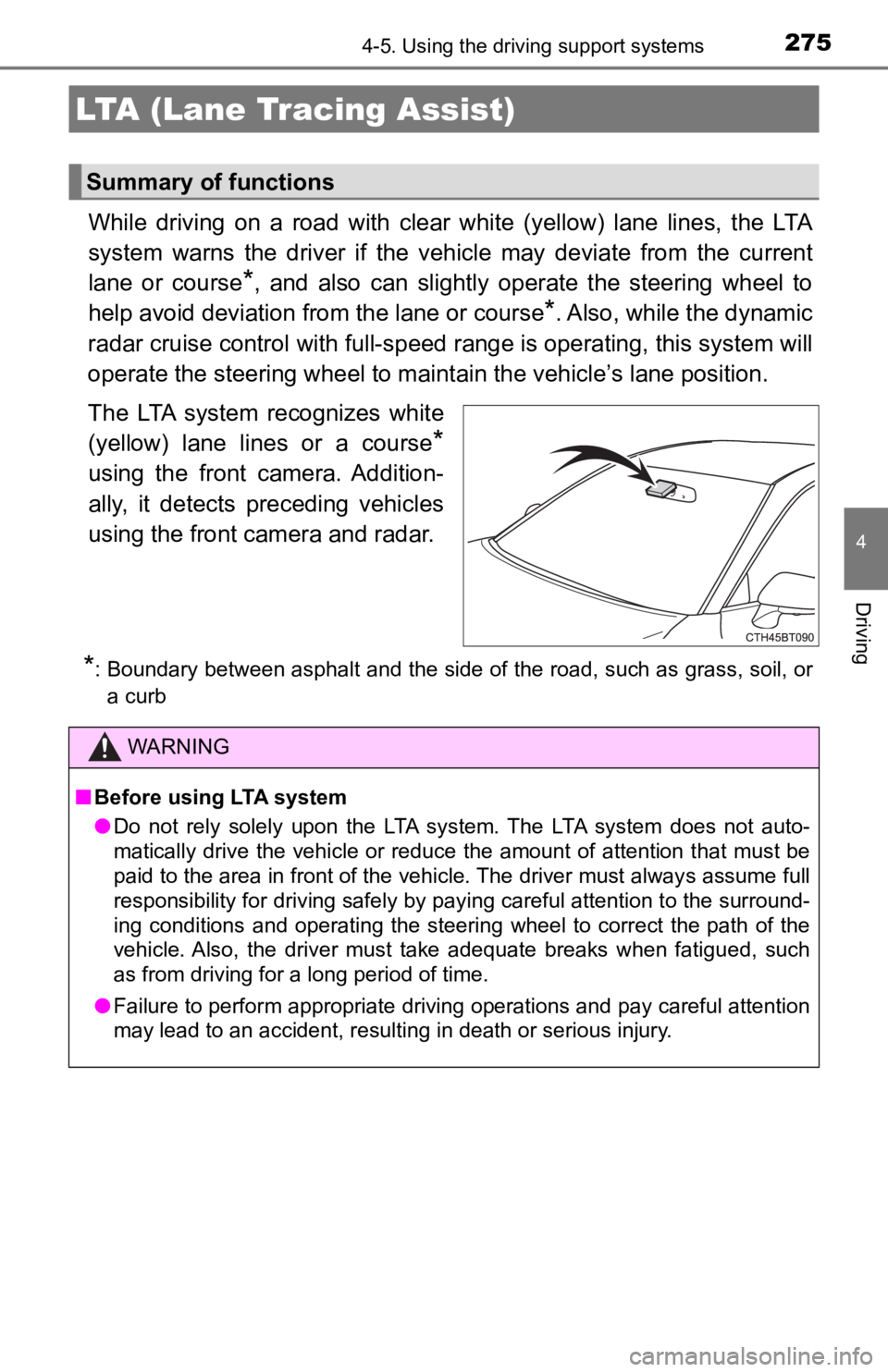
The LTA system recognizes white
(yellow) lane lines or a course
*
using the front camera. Addition-
ally, it detects preceding vehicles
using the front camera and radar.
*: Boundary between asphalt and the side of the road, such as gra ss, soil, or
a curb
LTA (Lane Tracing Assist)
Summary of functions
WARNING
■ Before using LTA system
● Do not rely solely upon the LTA system. The LTA system does not auto-
matically drive the vehicle or reduce the amount of attention t hat must be
paid to the area in front of the vehicle. The driver must always assume full
responsibility for driving safely by paying careful attention to the surround-
ing conditions and operating the steering wheel to correct the path of the
vehicle. Also, the driver must take adequate breaks when fatigued, such
as from driving for a long period of time.
● Failure to perform appropriate driving operations and pay careful attention
may lead to an accident, resulting in death or serious injury.
Page 296 of 624

2964-5. Using the driving support systems
WARNING
■Before using dynamic radar cruise control with full-speed range
● Driving safely is the sole responsibility of the driver. Do not rely solely on
the system, and drive safely by always paying careful attention to your sur-
roundings.
● The dynamic radar cruise control with full-speed range provides driving
assistance to reduce the driver's burden. However, there are li mitations to
the assistance provided.
Read the following conditions carefully. Do not overly rely on this system
and always drive carefully.
• When the sensor may not be correctly detecting the vehicle ahe ad:
P. 309
• Conditions under which the vehicle-to-vehicle distance control mode
may not function correctly: P. 310
● Set the speed appropriately depending on the speed limit, traffic flow, road
conditions, weather conditions, etc. The driver is responsible for checking
the set speed.
● Even when the system is functioning normally, the condition of the preced-
ing vehicle as detected by the system may differ from the condition
observed by the driver. Therefore, the driver must always remain alert,
assess the danger of each situation and drive safely. Relying s olely on this
system or assuming the system ensures safety while driving can lead to
an accident, resulting in death or serious injury.
● Switch the dynamic radar cruise control with full-speed range s etting to off,
using the cruise control main switch when not in use.
Page 299 of 624
2994-5. Using the driving support systems
4
Driving
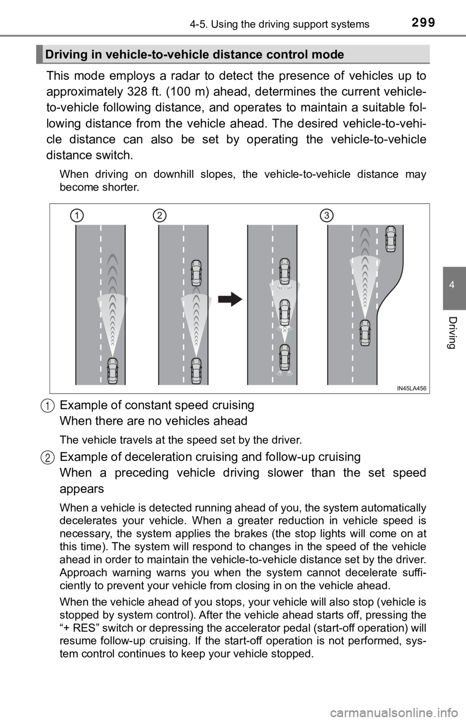
This mode employs a radar to detect the presence of vehicles up to
approximately 328 ft. (100 m) ahead, determines the current veh icle-
to-vehicle following distance, and operates to maintain a suita ble fol-
lowing distance from the vehicle ahead. The desired vehicle-to- vehi-
cle distance can also be set by operating the vehicle-to-vehicl e
distance switch.
When driving on downhill slopes, the vehicle-to-vehicle distance may
become shorter.
Example of constant speed cruising
When there are no vehicles ahead
The vehicle travels at the speed set by the driver.
Example of deceleration crui sing and follow-up cruising
When a preceding vehicle driving slower than the set speed
appears
When a vehicle is detected running ahead of you, the system automatically
decelerates your vehicle. When a greater reduction in vehicle s peed is
necessary, the system applies the brakes (the stop lights will come on at
this time). The system will respond to changes in the speed of the vehicle
ahead in order to maintain the vehicle-to-vehicle distance set by the driver.
Approach warning warns you when the system cannot decelerate su ffi-
ciently to prevent your vehicle from closing in on the vehicle ahead.
When the vehicle ahead of you stops, your vehicle will also stop (vehicle is
stopped by system control). After the vehicle ahead starts off, pressing the
“+ RES” switch or depressing the accelerator pedal (start-off o peration) will
resume follow-up cruising. If the start-off operation is not pe rformed, sys-
tem control continues to keep your vehicle stopped.
Driving in vehicle-to-vehi cle distance control mode
1
2
Page 302 of 624
3024-5. Using the driving support systems
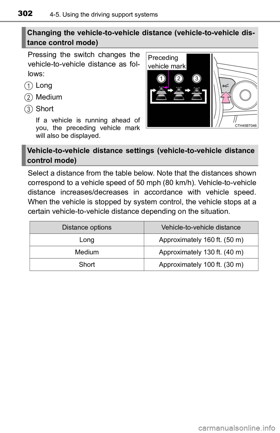
Pressing the switch changes the
vehicle-to-vehicle distance as fol-
lows:
Long
Medium
Short
If a vehicle is running ahead of
you, the preceding vehicle mark
will also be displayed.
Select a distance from the tabl e below. Note that the distances shown
correspond to a vehicle speed of 50 mph (80 km/h). Vehicle-to-v ehicle
distance increases/decreases in accordance with vehicle speed.
When the vehicle is stopped by system control, the vehicle stop s at a
certain vehicle-to-vehicle dista nce depending on the situation.
Changing the vehicle-to-vehicle d istance (vehicle-to-vehicle dis-
tance control mode)
Preceding
vehicle mark
1
2
3
Vehicle-to-vehicle distance settings (vehicle-to-vehicle distan ce
control mode)
Distance optionsVehicle-to-vehicle distance
LongApproximately 160 ft. (50 m)
MediumApproximately 130 ft. (40 m)
ShortApproximately 100 ft. (30 m)
Page 308 of 624

3084-5. Using the driving support systems
■Automatic cancelation of c onstant speed control mode
Constant speed control mode is automatically canceled in the following situa-
tions:
● Actual vehicle speed is more than approximately 10 mph (16 km/h ) below
the set vehicle speed.
● Actual vehicle speed falls below approximately 20 mph (30 km/h) .
● VSC is activated.
● TRAC is activated for a period of time.
● When the VSC or TRAC system is turned off.
● Pre-collision braking is activated.
If constant speed control mode is automatically canceled for any reasons
other than the above, there may be a malfunction in the system. Contact your
Toyota dealer.
■ Situations in which the curve speed reduction function may not operate
In situations such as the following, the curve speed reduction function may
not operate:
● When the vehicle is being driven around a gentle curve
● When the accelerator pedal is being depressed
● When the vehicle is being driven around an extremely short curve
■ Brake operation
A brake operation sound may be heard and the brake pedal response may
change, but these are not malfunctions.
■ Warning messages and buzzers for d ynamic radar cruise control with
full-speed range
Warning messages and buzzers are used to indicate a system malfunction or
to inform the driver of the need for caution while driving. If a warning message
is shown on the multi-information display, read the message and follow the
instructions. ( P. 258, 519)
Page 311 of 624
3114-5. Using the driving support systems
4
Driving
◆ECB (Electronically Controlled Brake System)
The electronically controlled system generates braking force corre-
sponding to the brake operation
◆ABS (Anti-lock Brake System)
Helps to prevent wheel lock when the brakes are applied suddenl y,
or if the brakes are applied while driving on a slippery road surface
◆Brake assist
Generates an increased level of braking force after the brake p edal
is depressed when the system de tects a panic stop situation
◆VSC (Vehicle Stability Control)
Helps the driver to control skidding when swerving suddenly or
turning on slippery road surfaces.
◆Enhanced VSC (Enhanced Vehicle Stability Control)
Provides cooperative control of the ABS, TRAC, VSC and EPS.
Helps to maintain directional stability when swerving on slippe ry
road surfaces by controlling steering performance.
◆Secondary Collision Brake
When the airbag sensor detects a collision and the system oper-
ates, the brakes and stop light s are automatically controlled to
reduce the vehicle speed and hel p reduce the possibility of further
damage due to a secondary collision
◆TRAC (Traction Control)
Helps to maintain drive power and prevent the drive wheels from
spinning when starting the vehicl e or accelerating on slippery roads
Driving assist systems
To keep driving safety and perf ormance, the following systems
operate automatically in respon se to various driving situations.
Be aware, however, that these systems are supplementary and
should not be relied upon too heav ily when operating the vehi-
cle.
Page 316 of 624
3164-5. Using the driving support systems
WARNING
■The ABS does not operate effectively when
● The limits of tire gripping performance have been exceeded (such as
excessively worn tires on a snow covered road).
● The vehicle hydroplanes while driving at high speed on wet or s lick roads.
■ Stopping distance when the ABS is operating may exceed that of nor-
mal conditions
The ABS is not designed to shorten the vehicle’s stopping distance. Always
maintain a safe distance from the vehicle in front of you, especially in the
following situations:
● When driving on dirt, gravel or snow-covered roads
● When driving with tire chains
● When driving over bumps on the road
● When driving over roads with potholes or uneven surfaces
■ TRAC/VSC may not operate effectively when
Directional control and power may not be achievable while driving on slip-
pery road surfaces, even if the TRAC/VSC system is operating.
Drive the vehicle carefully in conditions where stability and p ower may be
lost.
■ Hill- start assist control does not operate effectively when
● Do not overly rely on hill-start assist control. Hill-start assist control may
not operate effectively on steep inclines and roads covered wit h ice.
● Unlike the parking brake, hill-st art assist control is not intended to hold the
vehicle stationary for an extended period of time. Do not attempt to use
hill-start assist control to hold the vehicle on an incline, as doing so may
lead to an accident.
■ When the TRAC/ABS/VSC is activated
The slip indicator light flashes. Always drive carefully. Reckless driving may
cause an accident. Exercise particular care when the indicator light flashes.
■ When the TRAC/VSC systems are turned off
Be especially careful and drive at a speed appropriate to the r oad condi-
tions. As these are the systems to help ensure vehicle stability and driving
force, do not turn the TRAC/VSC systems off unless necessary.
■ Secondary Collision Brake
Do not overly rely solely upon the Secondary Collision Brake. This system
is designed to help reduce the possibility of further damage due to a sec-
ondary collision, however, that effect changes according to various condi-
tions. Overly relying on the system may result in death or serious injury.
Page 322 of 624
3224-5. Using the driving support systems
WARNING
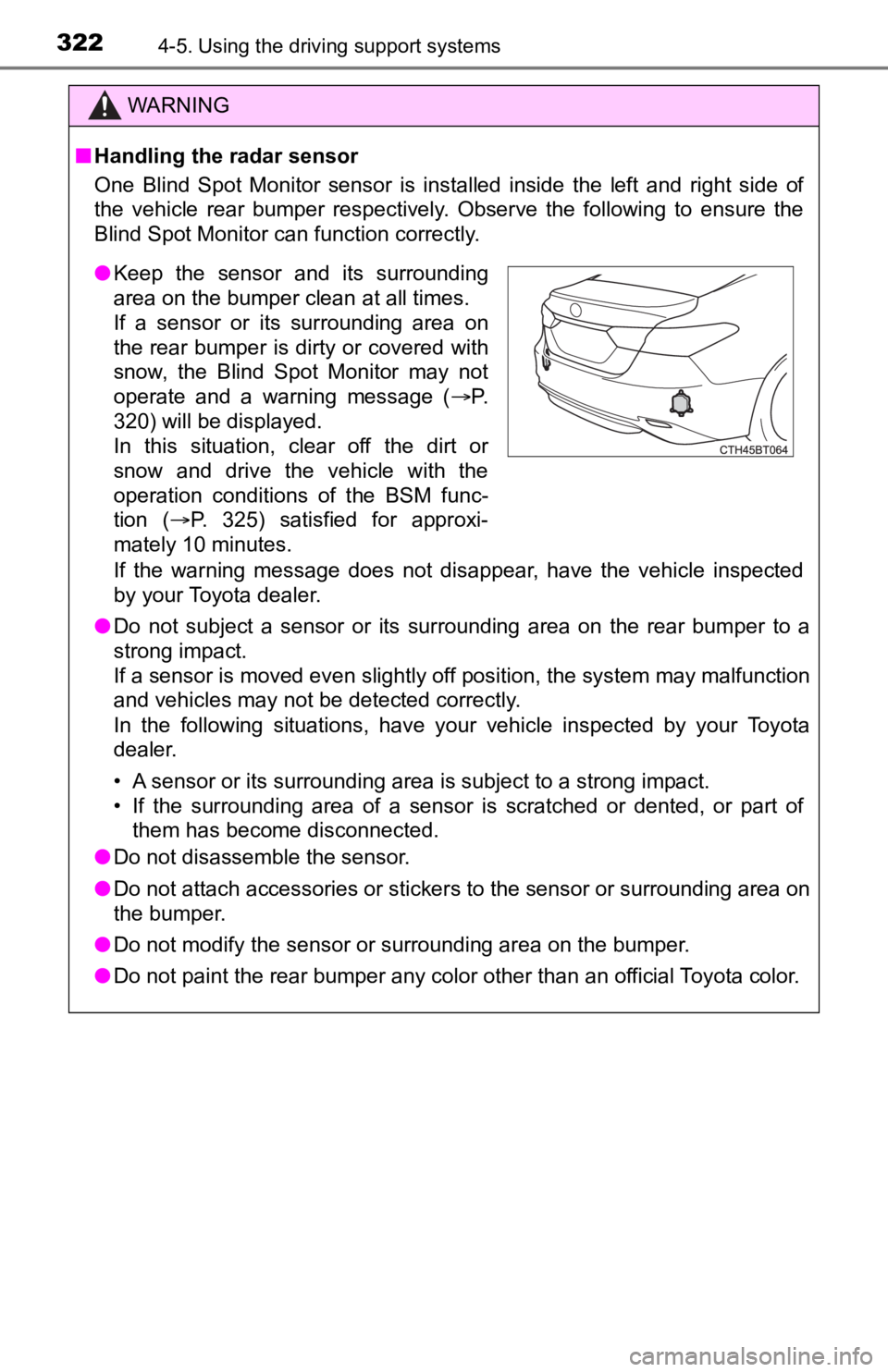
■Handling the radar sensor
One Blind Spot Monitor sensor is installed inside the left and right side of
the vehicle rear bumper respectively. Observe the following to ensure the
Blind Spot Monitor can function correctly.
If the warning message does not disappear, have the vehicle inspected
by your Toyota dealer.
● Do not subject a sensor or its surrounding area on the rear bumper to a
strong impact.
If a sensor is moved even slightly off position, the system may malfunction
and vehicles may not be detected correctly.
In the following situations, have your vehicle inspected by you r Toyota
dealer.
• A sensor or its surrounding area is subject to a strong impact .
• If the surrounding area of a sensor is scratched or dented, or part of them has become disconnected.
● Do not disassemble the sensor.
● Do not attach accessories or stickers to the sensor or surrounding area on
the bumper.
● Do not modify the sensor or surrounding area on the bumper.
● Do not paint the rear bumper any color other than an official Toyota color.
●Keep the sensor and its surrounding
area on the bumper clean at all times.
If a sensor or its surrounding area on
the rear bumper is dirty or covered with
snow, the Blind Spot Monitor may not
operate and a warning message ( P.
320) will be displayed.
In this situation, clear off the dirt or
snow and drive the vehicle with the
operation conditions of the BSM func-
tion ( P. 325) satisfied for approxi-
mately 10 minutes.
Page 324 of 624
3244-5. Using the driving support systems
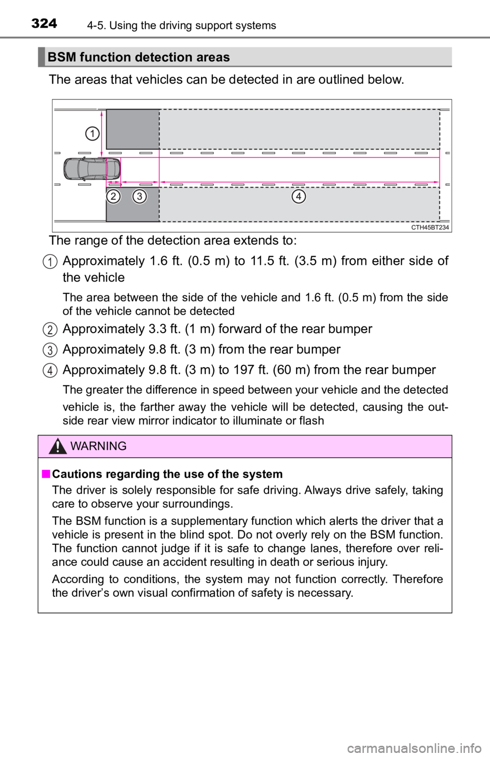
The areas that vehicles can be detected in are outlined below.
The range of the detecti on area extends to:
Approximately 1.6 ft. (0.5 m) to 11.5 ft. (3.5 m) from either s ide of
the vehicle
The area between the side of the vehicle and 1.6 ft. (0.5 m) fr om the side
of the vehicle cannot be detected
Approximately 3.3 ft. (1 m) f orward of the rear bumper
Approximately 9.8 ft. (3 m) from the rear bumper
Approximately 9.8 ft. (3 m) to 19 7 ft. (60 m) from the rear bumper
The greater the difference in speed between your vehicle and the detected
vehicle is, the farther away the vehicle will be detected, causing the out-
side rear view mirror indicator to illuminate or flash
BSM function detection areas
1
2
3
4
WARNING
■Cautions regarding the use of the system
The driver is solely responsible for safe driving. Always drive safely, taking
care to observe your surroundings.
The BSM function is a supplementary function which alerts the d river that a
vehicle is present in the blind spot. Do not overly rely on the BSM function.
The function cannot judge if it is safe to change lanes, theref ore over reli-
ance could cause an accident resulting in death or serious inju r y.
According to conditions, the system may not function correctly. Therefore
the driver’s own visual confirmation of safety is necessary.
Page 330 of 624
3304-5. Using the driving support systems
■Buzzer operation and distance to an object
A buzzer sounds when the sensors are operating.
● The buzzer sounds faster as the vehicle approaches an object.
When the vehicle comes within the following distance of the
object, the buzzer sounds continuo usly: Approximately 1.2 ft. (35
cm).
● When 2 or more objects are detec ted simultaneously, the buzzer
system responds to the nearest object. If one or both come with in
the above distances, the beep will repeat a long tone, followed by
fast beeps.
● Automatic buzzer mute function
After a buzzer begins sounding, if the distance between the veh i-
cle and the detected object does not become shorter, the buzzer
will be muted automatically.
(However, if the distance between the vehicle and object is 1.0 ft.
(30 cm) or less, this function will not operate.)
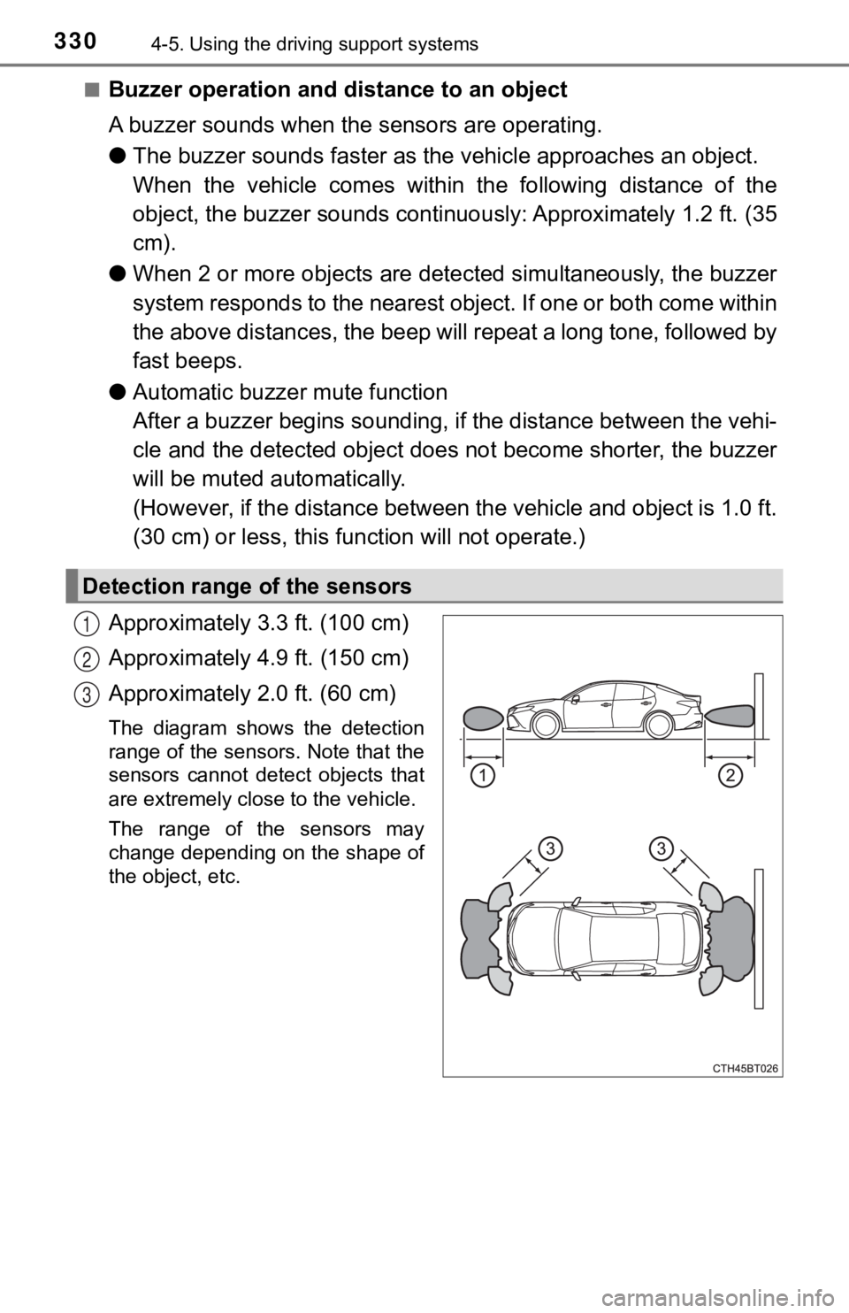
Approximately 3.3 ft. (100 cm)
Approximately 4.9 ft. (150 cm)
Approximately 2.0 ft. (60 cm)
The diagram shows the detection
range of the sensors. Note that the
sensors cannot detect objects that
are extremely close to the vehicle.
The range of the sensors may
change depending on the shape of
the object, etc.
Detection range of the sensors
1
2
3