rear view mirror TOYOTA COROLLA CROSS 2023 User Guide
[x] Cancel search | Manufacturer: TOYOTA, Model Year: 2023, Model line: COROLLA CROSS, Model: TOYOTA COROLLA CROSS 2023Pages: 500, PDF Size: 15.11 MB
Page 131 of 500
1313-4. Adjusting the steering wheel and mirrors
3
Before driving
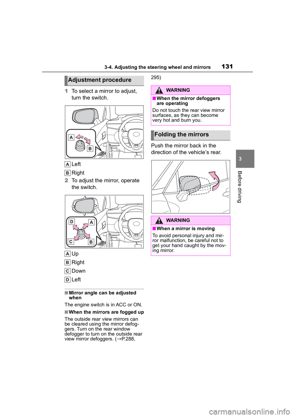
1To select a mirror to adjust,
turn the switch.
Left
Right
2 To adjust the mirror, operate
the switch.
Up
Right
Down
Left
■Mirror angle can be adjusted
when
The engine switch is in ACC or ON.
■When the mirrors are fogged up
The outside rear v iew mirrors can
be cleared using the mirror defog-
gers. Turn on the rear window
defogger to turn on the outside rear
view mirror defoggers. ( P.288, 295)
Push the mirror back in the
direction of the vehicle’s rear.
Adjustment procedure
WARNING
■When the mirror defoggers
are operating
Do not touch the rear view mirror
surfaces, as they can become
very hot and burn you.
Folding the mirrors
WARNING
■When a mirror is moving
To avoid personal injury and mir-
ror malfunction, be careful not to
get your hand caught by the mov-
ing mirror.
Page 143 of 500
1434-1. Before driving
4
Driving
WARNING
●During normal driving, do not
turn off the engine. Turning the
engine off while driving will not
cause loss of steering or brak-
ing control, but the power assist
to these systems will be lost.
This will make it more difficult to
steer and brake, so you should
pull over and stop the vehicle as
soon as it is safe to do so.
However, in the event of an
emergency, such as if it
becomes impossible to stop the
vehicle in the normal way:
P. 3 8 2
●Use engine braking (downshift)
to maintain a safe speed when
driving down a steep hill.
Using the brakes continuously
may cause the brakes to over-
heat and lose effectiveness.
(
P.168)
●Do not adjust the positions of
the steering wheel, the seat, or
the inside or outside rear view
mirrors while driving.
Doing so may result in a loss of
vehicle control.
●Always check that all passen-
gers’ arms, heads or other parts
of their body are not outside the
vehicle.
●AWD models: Do not drive the
vehicle off-road.
This is not an AWD vehicle
designed for off-road driving.
Proceed with all due caution if it
becomes unavoidable to drive
off-road.
●AWD models: Do not drive
across a river or through other
bodies of water.
This may cause electric/elec-
tronic components to short cir-
cuit, damage the engine or
cause other serious damage to
the vehicle.
●Do not drive in excess of the
speed limit. Even if the legal
speed limit permits it, do not
drive over 85 mph (140 km/h)
unless your vehicle has
high-speed capability tires. Driv-
ing over 85 mph (140 km/h)
may result in tire failure, loss of
control and possible injury. Be
sure to consult a tire dealer to
determine whether the tires on
your vehicle are high-speed
capability tires or not before
driving at such speeds.
■When driving on slippery
road surfaces
●Sudden braking, acceleration
and steering may cause tire
slippage and reduce your ability
to control the vehicle.
●Sudden acceleration, engine
braking due to shifting, or
changes in engine speed could
cause the vehicle to skid.
●After driving through a puddle,
lightly depress the brake pedal
to make sure that the brakes
are functioning properly. Wet
brake pads may prevent the
brakes from functioning prop-
erly. If the brakes on only one
side are wet and not functioning
properly, steering control may
be affected.
■When shifting the shift lever
●Do not let the vehicle roll back-
ward while a fo rward driving
position is selected, or roll for-
ward while the shift lever is in R.
Doing so may cause the engine
to stall or lead to poor brake and
steering performance, resulting
in an accident or damage to the
vehicle.
Page 152 of 500
1524-1. Before driving
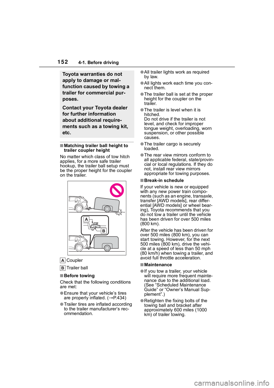
■Matching trailer ball height to
trailer coupler height
No matter which class of tow hitch
applies, for a more safe trailer
hookup, the trailer ball setup must
be the proper height for the coupler
on the trailer.
Coupler
Trailer ball
■Before towing
Check that the following conditions
are met:
●Ensure that your vehicle’s tires
are properly inflated. ( P.434)
●Trailer tires are inflated according
to the trailer manufacturer’s rec-
ommendation.
●All trailer lights work as required
by law.
●All lights work each time you con-
nect them.
●The trailer ball is set at the proper
height for the coupler on the
trailer.
●The trailer is level when it is
hitched.
Do not drive if th e trailer is not
level, and check for improper
tongue weight, overloading, worn
suspension, or other possible
causes.
●The trailer cargo is securely
loaded.
●The rear view mirr ors conform to
all applicable fede ral, state/provin-
cial or local regulations. If they do
not, install rear view mirrors
appropriate for towing purposes.
■Break-in schedule
If your vehicle is new or equipped
with any new power train compo-
nents (such as an engine, transaxle,
transfer [AWD models], rear differ-
ential [AWD models] or wheel bear-
ing), Toyota recommends that you
do not tow a trailer until the vehicle
has been driven for over 500 miles
(800 km).
After the vehicle has been driven for
over 500 miles (800 km), you can
start towing. However, for the next
500 miles (800 km), drive the vehi-
cle at a speed of less than 50 mph
(80 km/h) when towing a trailer, and
avoid full throttle acceleration.
■Maintenance
●If you tow a trailer, your vehicle
will require more fr equent mainte-
nance due to the additional load.
(See “Scheduled Maintenance
Guide” or “Owner ’s Manual Sup-
plement”.)
●Retighten the fixing bolts of the
towing ball and bracket after
approximately 600 miles (1000
km) of tra iler towing.
Toyota warranties do not
apply to damage or mal-
function caused by towing a
trailer for commercial pur-
poses.
Contact your Toyota dealer
for further information
about additional require-
ments such as a towing kit,
etc.
Page 195 of 500
1954-5. Using the driving support systems
4
Driving
WARNING
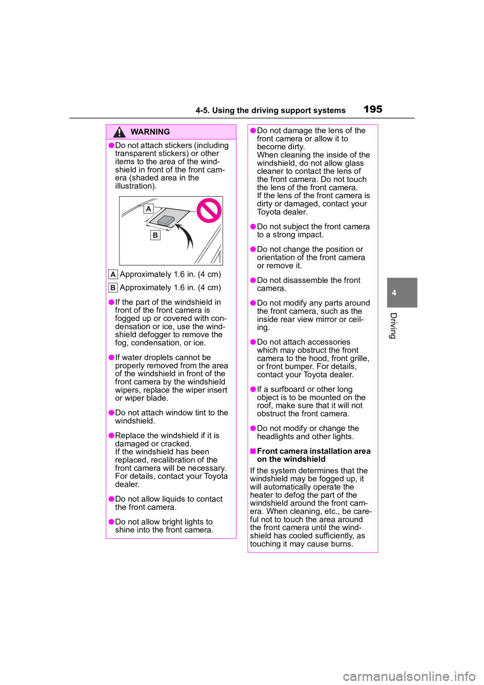
●Do not attach stickers (including
transparent stickers) or other
items to the area of the wind-
shield in front of the front cam-
era (shaded area in the
illustration).
Approximately 1.6 in. (4 cm)
Approximately 1.6 in. (4 cm)
●If the part of the windshield in
front of the front camera is
fogged up or covered with con-
densation or ice, use the wind-
shield defogger to remove the
fog, condensation, or ice.
●If water droplets cannot be
properly removed from the area
of the windshield in front of the
front camera by the windshield
wipers, replace the wiper insert
or wiper blade.
●Do not attach win dow tint to the
windshield.
●Replace the windshield if it is
damaged or cracked.
If the windshield has been
replaced, recalib ration of the
front camera will be necessary.
For details, contact your Toyota
dealer.
●Do not allow liquids to contact
the front camera.
●Do not allow bright lights to
shine into the front camera.
●Do not damage th e lens of the
front camera o r allow it to
become dirty.
When cleaning the inside of the
windshield, do not allow glass
cleaner to contact the lens of
the front camera. Do not touch
the lens of the front camera.
If the lens of the front camera is
dirty or damaged, contact your
Toyota dealer.
●Do not subject the front camera
to a strong impact.
●Do not change the position or
orientation of the front camera
or remove it.
●Do not disassemble the front
camera.
●Do not modify any parts around
the front camera , such as the
inside rear view mirror or ceil-
ing.
●Do not attach accessories
which may obstruct the front
camera to the hood, front grille,
or front bumper. For details,
contact your Toyota dealer.
●If a surfboard or other long
object is to be mounted on the
roof, make sure that it will not
obstruct the front camera.
●Do not modify or change the
headlights and other lights.
■Front camera installation area
on the windshield
If the system determines that the
windshield may be fogged up, it
will automatically operate the
heater to defog t he part of the
windshield aroun d the front cam-
era. When cleaning, etc., be care-
ful not to touch the area around
the front camera until the wind-
shield has cooled sufficiently, as
touching it may cause burns.
Page 243 of 500
2434-5. Using the driving support systems
4
Driving
*: If equipped
NOTICE
■To ensure the system oper-
ates correctly
If any of the following situations
occur, the Stop & Start system
may not operate correctly. Have
your vehicle inspected by your
Toyota dealer.
●While the driver’s seat belt is
fastened, the driver’s and front
passenger’s seat belt reminder
light flashes.
●Even though the driver’s seat
belt is not fastened, the driver’s
and front passenger’s seat belt
reminder light does not illumi-
nate.
●Even though the driver’s door is
closed, the open door warning
light is illuminated or the interior
light is illuminated when the
interior light switch is in the door
position.
●Even though the driver’s door is
open, the open door warning
light does not illuminate or the
interior light does not illuminate
when the interior light switch is
in the door position.
BSM (Blind Spot Moni-
tor)*
The Blind Spot Monitor is a
system that uses rear side
radar sensors installed on
the inner side of the rear
bumper on the left and right
side to assist the driver in
confirming safety when
changing lanes.
WARNING
■Cautions regarding the use of
the system
●The driver is solely responsible
for safe driving. Always drive
safely, taking care to observe
your surroundings.
●The Blind Spot Monitor is a sup-
plementary function which alerts
the driver that a vehicle is in a
blind spot of the outside rear
view mirrors or is approaching
rapidly from behind into a blind
spot. Do not overly rely on the
Blind Spot Monitor. As the func-
tion cannot judge if it is safe to
change lanes, over reliance
could lead to an accident result-
ing in death or serious injury. As
the system may not function
correctly under certain condi-
tions, the driver’s own visual
confirmation of safety is neces-
sary.
Page 244 of 500
2444-5. Using the driving support systems
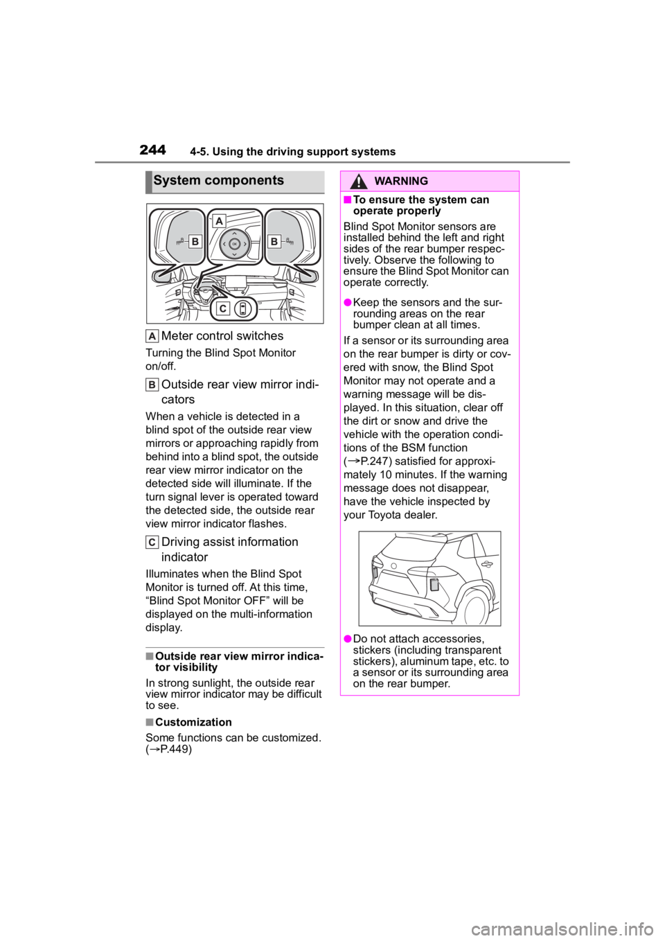
Meter control switches
Turning the Blind Spot Monitor
on/off.
Outside rear view mirror indi-
cators
When a vehicle is detected in a
blind spot of the outside rear view
mirrors or approaching rapidly from
behind into a blind spot, the outside
rear view mirror indicator on the
detected side will illuminate. If the
turn signal lever is operated toward
the detected side, the outside rear
view mirror indicator flashes.
Driving assist information
indicator
Illuminates when the Blind Spot
Monitor is turned of f. At this time,
“Blind Spot Monitor OFF” will be
displayed on the multi-information
display.
■Outside rear view mirror indica-
tor visibility
In strong sunlight, the outside rear
view mirror indicato r may be difficult
to see.
■Customization
Some functions can be customized.
( P.449)
System componentsWARNING
■To ensure the system can
operate properly
Blind Spot Monitor sensors are
installed behind the left and right
sides of the rear bumper respec-
tively. Observe the following to
ensure the Blind Spot Monitor can
operate correctly.
●Keep the sensors and the sur-
rounding areas on the rear
bumper clean at all times.
If a sensor or its surrounding area
on the rear bumper is dirty or cov-
ered with snow, the Blind Spot
Monitor may not operate and a
warning message will be dis-
played. In this situation, clear off
the dirt or snow and drive the
vehicle with the operation condi-
tions of the BSM function
(
P.247) satisfied for approxi-
mately 10 minutes. If the warning
message does not disappear,
have the vehicle inspected by
your Toyota dealer.
●Do not attach a ccessories,
stickers (including transparent
stickers), aluminum tape, etc. to
a sensor or its surrounding area
on the rear bumper.
Page 245 of 500
2454-5. Using the driving support systems
4
Driving
The Blind Spot Monitor can be
enabled/disabled on or
of the multi-information display.
(P.449)
When the Blind Spot Monitor
function is off, the driving assist
information indicator ( P.74)
will illuminate. At this time,
“Blind Spot Monitor OFF” will be
displayed on the multi-informa-
tion display.
Each time the engine switch is
turned to ON, the Blind Spot
Monitor is enabled.
■Objects that can be detected while driving
The Blind Spot Monitor uses rear side radar sensors to detect the fol-
lowing vehicles traveling in adjacent lanes and advises the driver of
the presence of such vehicles via the indicators on the outside rear
view mirrors.
WARNING
●Do not subject a sensor or its
surrounding area on the rear
bumper to a strong impact.
If a sensor is moved even
slightly off position, the system
may malfunction and vehicles
may not be detected correctly.
In the following si tuations, have
your vehicle inspected by your
Toyota dealer.
• A sensor or its surrounding area is subject to a strong impact.
• If the surrounding area of a sen- sor is scratched or dented, or
part of them has become dis-
connected.
●Do not disassemble the sensor.
●Do not modify the sensor or sur-
rounding area on the rear
bumper.
●If a sensor or th e rear bumper
needs to be removed/installed
or replaced, contact your Toyota
dealer.
●Do not paint the rear bumper
any color other t han an official
Toyota color.
Turning the Blind Spot
Monitor on/off
Blind Spot Monitor operation
Page 246 of 500
2464-5. Using the driving support systems
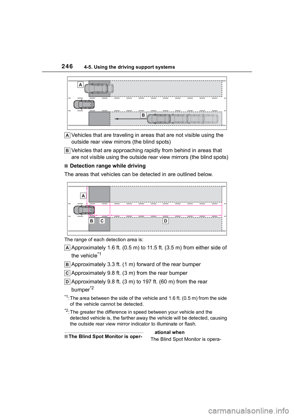
Vehicles that are traveling in areas that are not visible using the
outside rear view mirrors (the blind spots)
Vehicles that are approaching r apidly from behind in areas that
are not visible using the outside rear view mirrors (the blind spots)
■Detection range while driving
The areas that vehicles can be detected in are outlined below.
The range of each detection area is:
Approximately 1.6 ft. (0.5 m) to 11.5 ft. (3.5 m) from either s ide of
the vehicle
*1
Approximately 3.3 ft. (1 m) forward of the rear bumper
Approximately 9.8 ft. (3 m) from the rear bumper
Approximately 9.8 ft. (3 m) to 197 ft. (60 m) from the rear
bumper
*2
*1: The area between the side of the vehicle and 1.6 ft. (0.5 m) f rom the side
of the vehicle cannot be detected.
*2: The greater the difference in speed between your vehicle and t he
detected vehicle is, the farthe r away the vehicle will be detec ted, causing
the outside r ear view mirror indicato r to illuminate or flash.
■The Blind Spot Monitor is oper- ational when
The Blind Spot Monitor is opera-
Page 249 of 500
2494-5. Using the driving support systems
4
Driving
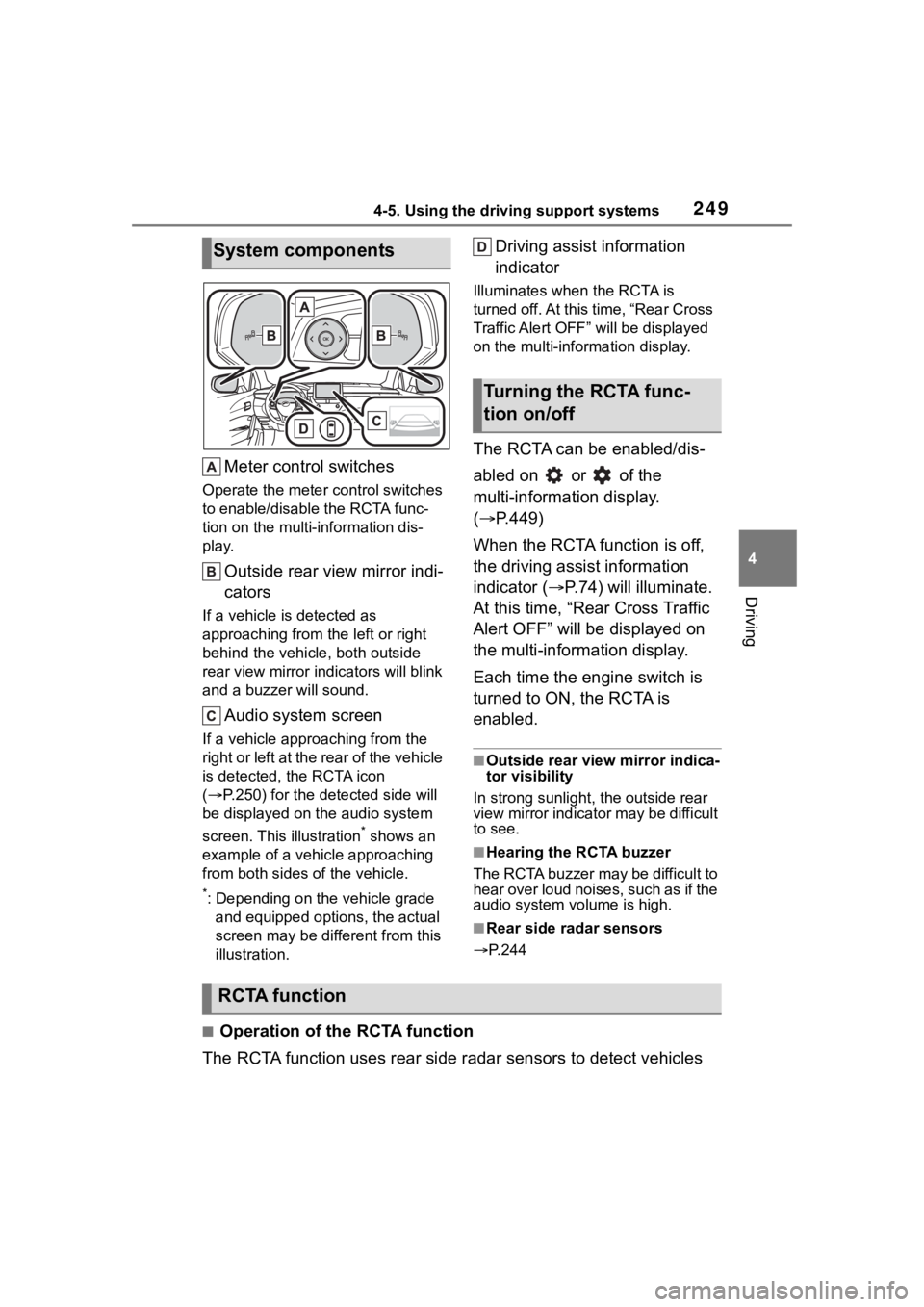
Meter control switches
Operate the meter control switches
to enable/disable the RCTA func-
tion on the multi-information dis-
play.
Outside rear view mirror indi-
cators
If a vehicle is detected as
approaching from the left or right
behind the vehicle, both outside
rear view mirror indicators will blink
and a buzzer will sound.
Audio system screen
If a vehicle appr oaching from the
right or left at the rear of the vehicle
is detected, the RCTA icon
( P.250) for the det ected side will
be displayed on t he audio system
screen. This illustration
* shows an
example of a vehicle approaching
from both sides of the vehicle.
*: Depending on the vehicle grade and equipped options, the actual
screen may be different from this
illustration.
Driving assist information
indicator
Illuminates when the RCTA is
turned off. At this time, “Rear Cross
Traffic Alert OFF” will be displayed
on the multi-information display.
The RCTA can be enabled/dis-
abled on or of the
multi-information display.
( P.449)
When the RCTA function is off,
the driving assist information
indicator ( P.74) will illuminate.
At this time, “Rear Cross Traffic
Alert OFF” will be displayed on
the multi-information display.
Each time the engine switch is
turned to ON, the RCTA is
enabled.
■Outside rear vie w mirror indica-
tor visibility
In strong sunlight, the outside rear
view mirror indicator may be difficult
to see.
■Hearing the RCTA buzzer
The RCTA buzzer may be difficult to
hear over loud noises, such as if the
audio system volume is high.
■Rear side radar sensors
P.244
■Operation of the RCTA function
The RCTA function uses rear side radar sensors to detect vehicles
System components
Turning the RCTA func-
tion on/off
RCTA function
Page 250 of 500
2504-5. Using the driving support systems
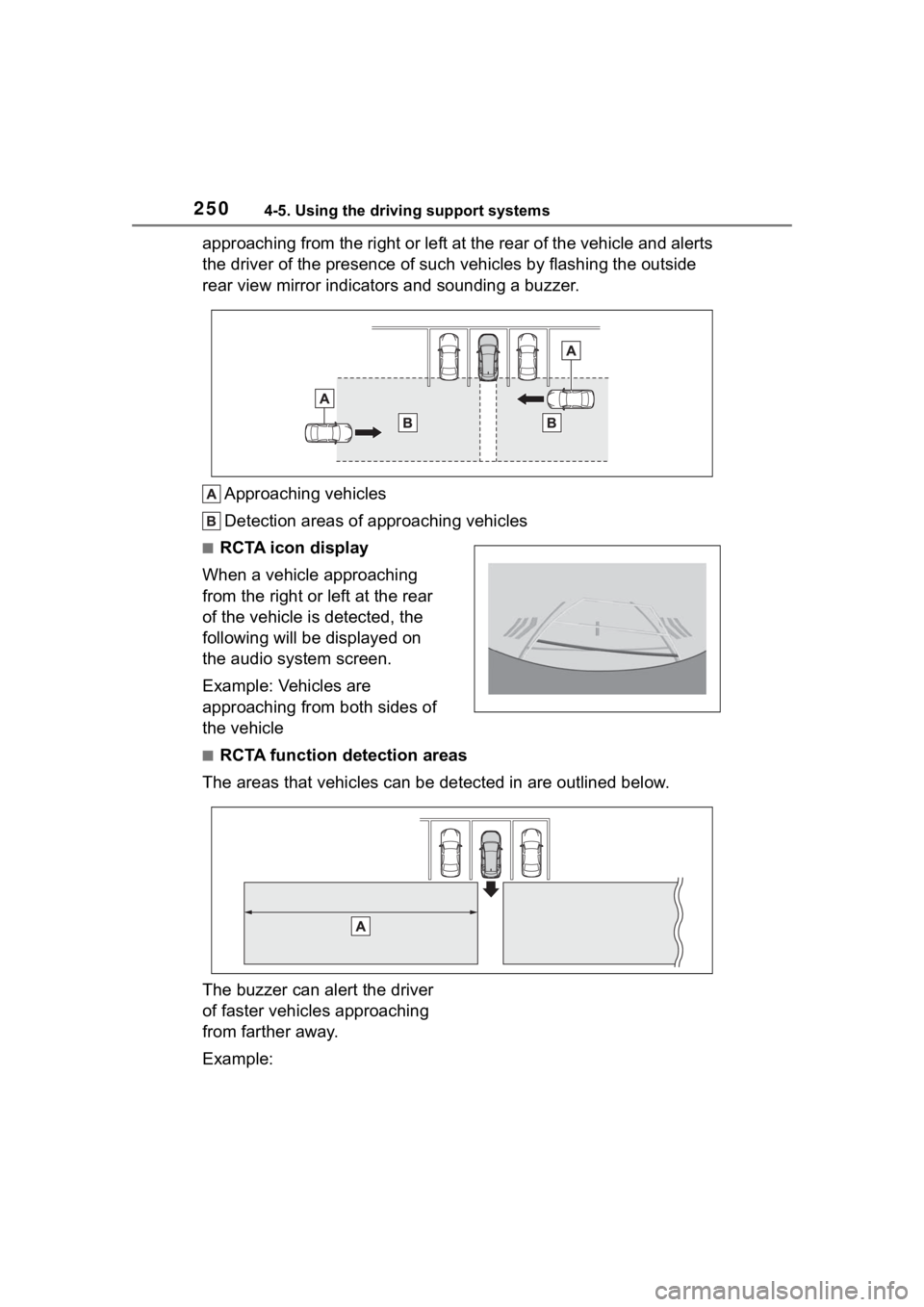
approaching from the right or left at the rear of the vehicle and alerts
the driver of the presence of such vehicles by flashing the out side
rear view mirror indicators and sounding a buzzer.
Approaching vehicles
Detection areas of approaching vehicles
■RCTA icon display
When a vehicle approaching
from the right or left at the rear
of the vehicle is detected, the
following will be displayed on
the audio system screen.
Example: Vehicles are
approaching from both sides of
the vehicle
■RCTA function detection areas
The areas that vehicles can be detected in are outlined below.
The buzzer can alert the driver
of faster vehicles approaching
from farther away.
Example: